relay ISUZU TROOPER 1995 Workshop Manual
[x] Cancel search | Manufacturer: ISUZU, Model Year: 1995, Model line: TROOPER, Model: ISUZU TROOPER 1995Pages: 1928
Page 1460 of 1928
8-270 CHASSIS ELECTRICAL
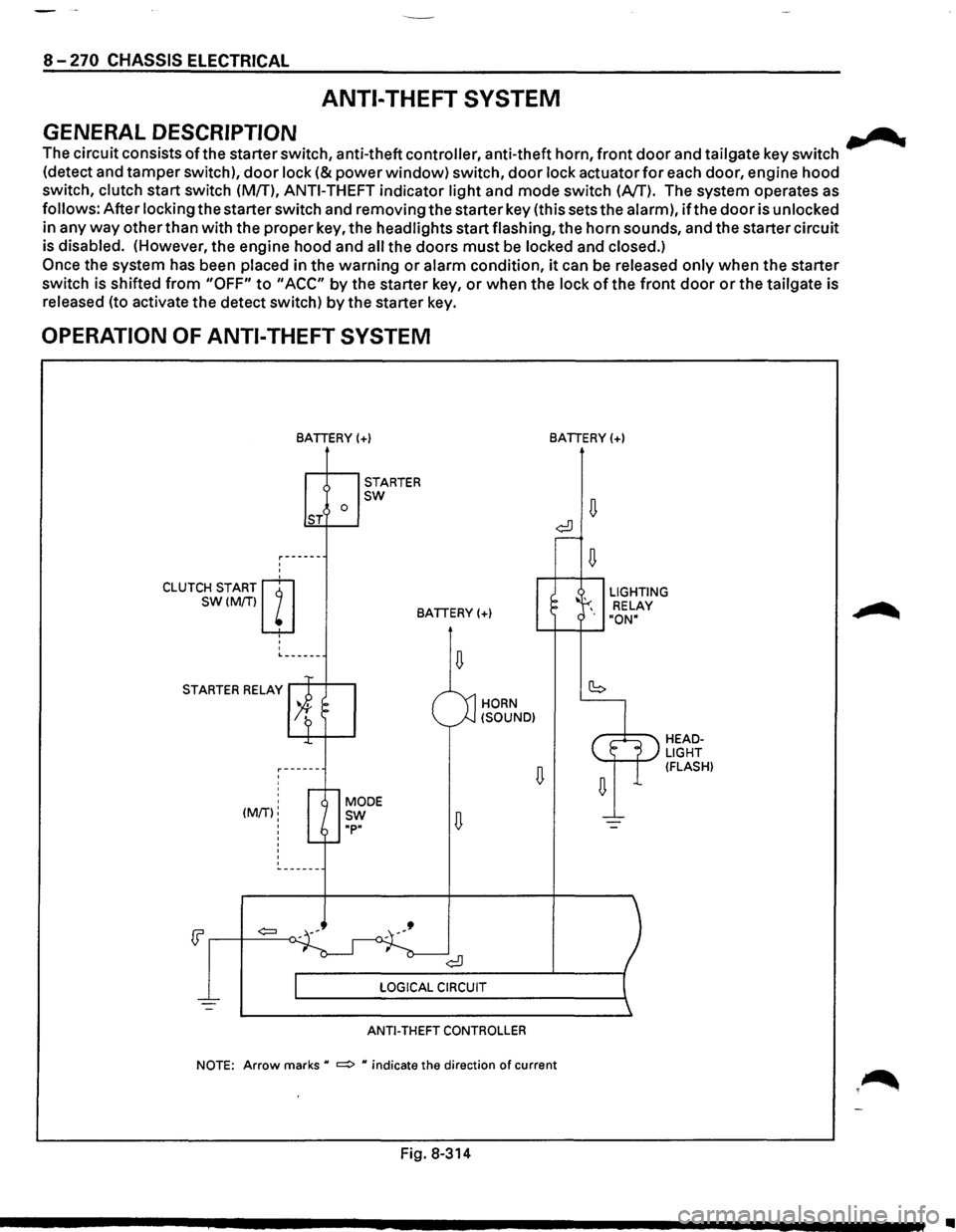
ANTI-THEFT SYSTEM
GENERAL DESCRIPTION .......
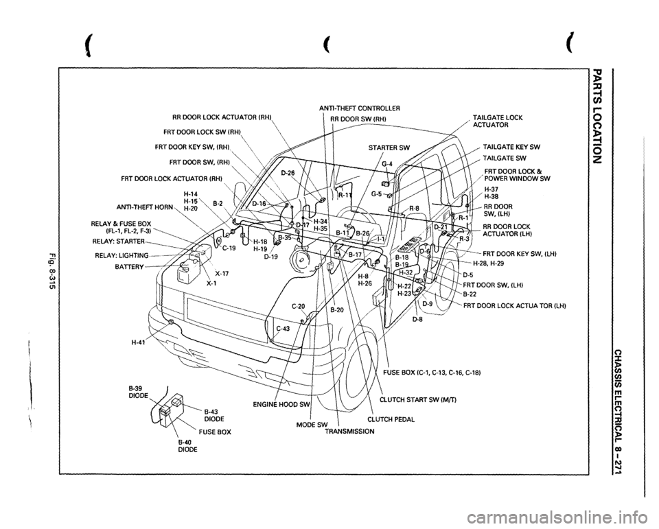
The circuit consists ofthe starter switch, anti-theft controller, anti-theft horn, front door and tailgate key switch
(detect and tamper switch),
door lock (&power window) switch, door lock actuator for each door, engine hood
switch, clutch start switch (MfT),
ANTI-THEFT indicator light and mode switch (AfT). The system operates as
follows: After locking the starter switch and removing the starter key (this sets the alarm),
ifthe door is unlocked
in any
way other than with the proper key, the headlights start flashing, the horn sounds, and the starter circuit
is disabled. (However,
the engine hood and all the doors must be locked and closed.)
Once the system has been placed in the warning or alarm condition, it can be released only when the starter
switch is shifted
from "OFF" to "ACC" by the starter key, or when the lock of the front door or the tailgate is
released (to activate the detect switch)
by the starter key.
OPERATION OF ANTI-THEFT SYSTEM
'
'
CLUTCH START m
SW(M/Tiw
' '
'
BATIERY(+)
0 ST
STARTER sw
BATIERY(+)
L------
STARTER RELAY
' ' (MIT):
'
'
'
HORN
(SOUND)
ANTI-THEFT CONTROLLER
BATIERY(+)
LIGHTING
RELAY
"ON"
HEADLIGHT (FLASH)
NOTE: Arrow marks u ~ u indicate the direction of current
Fig. 8-314
•
Page 1461 of 1928
'"T1 !fl' co I w _. (11
I i i, ~
(
RR
DOOR
LOCK
ACTUATOR
{RHJ
FRT
DOOR
LOCK
SW
(RH
FRT
DOOR
KEY
SW,
(RH),
( ANTI-THEFT
CONTROLLER
RR
DOOR
SW
(RHJ
-------
FRT
DOOR
SW,
(RH)
.~""··
\
/;'~
~
"'··
FRT
DOOR
LOCK
ACTUATOR
(RH)
'-, ..,/j.
',
H-14
'L
y'JIJ.
"·,
H-15"
82
ANTI-THEFT
HORN~-20
"-,
-
RELAY
& FUSE
BOX
~
{FL-1,
FL-2,
F-3)
~
RELAY:
STARTER BATTERY
X::
H-41 B-39 DIODE
B-40 DIODE
B-43 DIODE FUSE
BOX MODESW
TRANSMISSION ,
TAILGATE
LOCK
ACTUATOR
TAILGATE
KEY
SW
TAILGATESW
FRT
DOOR
LOCK
&
/'POWER
WINDOW
SW
H-37 H-38 RRDOOR SW,(LH)
.
RR
DOOR
LOCK
-~ACTUATOR
{LHJ
FRT
DOOR
KEY
SW,
{LH)
-H-28,
H-29
FRT
DOOR
LOCK
ACTUA
TOR
(LH)
(
;g ~ C/) 5 C') ~ 0 z
n :X: ~ (/) 0 m rm ~ n ):a r-0) I N ..... -
Page 1475 of 1928
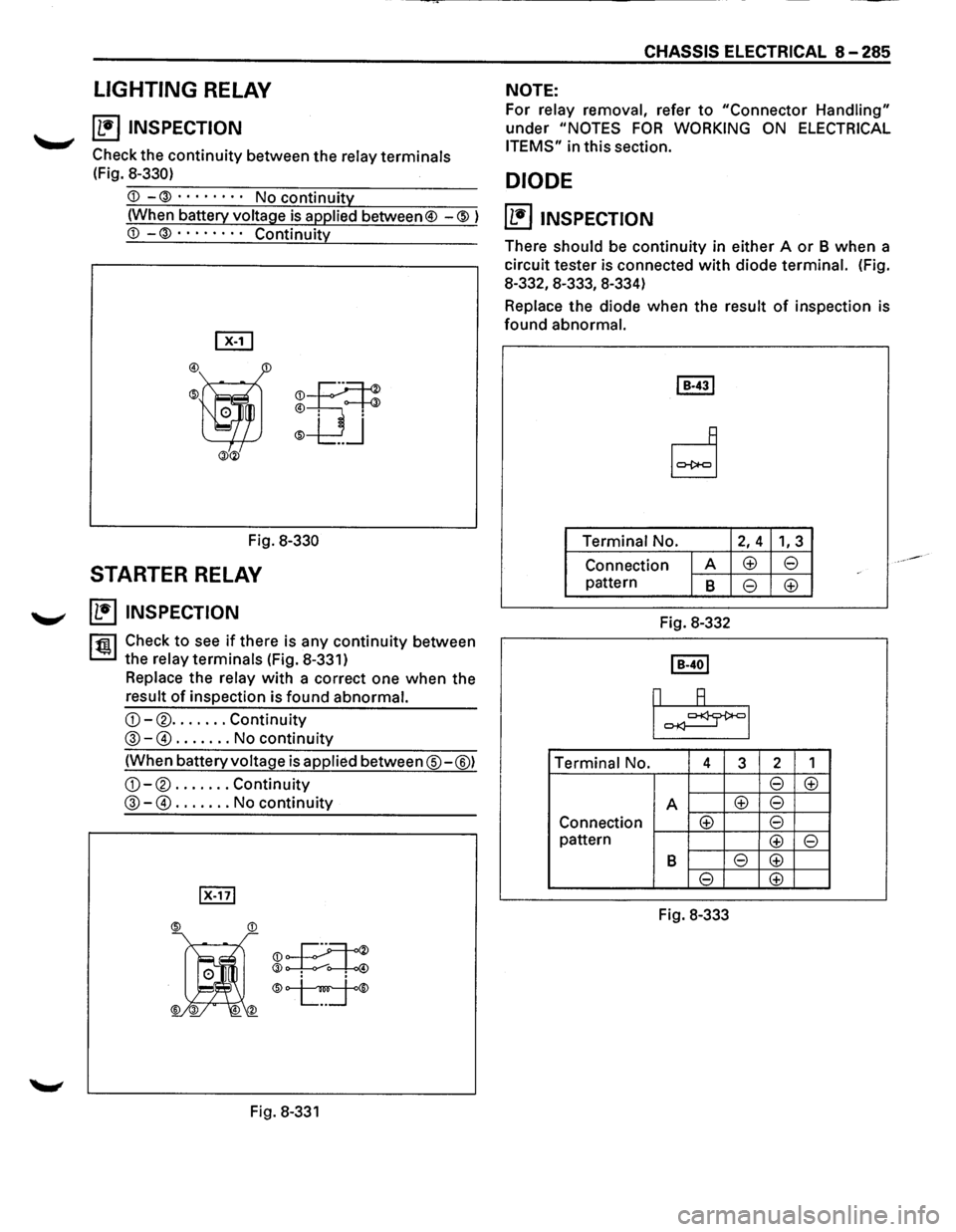
LIGHTING RELAY
~ ~ INSPECTION
Check the continuity between the relay terminals
(Fig.
8-330)
is applied between® -@ )
Fig. 8-330
STARTER RELAY
~ INSPECTION
rfii1 Check to see if there is any continuity between
~the relay terminals (Fig. 8-331)
Replace the relay with a correct one when the
result
of inspection is found abnormal.
G)-® ....... Continuity
@-@) ....... No continuity
(When battery voltage is applied between®-@)
G)-® ....... Continuity
@-@) ....... No continuity
®K
®~® ® •.
Fig. 8-331
CHASSIS ELECTRICAL 8-285
NOTE:
For relay removal, refer to "Connector Handling"
under
"NOTES FOR WORKING ON ELECTRICAL
ITEMS" in this section.
DIODE
(1!] INSPECTION
There should be continuity in either A or B when a
circuit tester
is connected with diode terminal. (Fig.
8-332,8-333, 8-334)
Replace the diode when the result of inspection is
found abnormal.
Terminal No.
2, 4 1, 3
Connection A <±> 8
pattern B 8 <±>
Fig. 8-332
Terminal
No. 4 3 2 1
8 <±>
A <±> 8
Connection <±> 8
pattern <±> 8
B 8 <±>
8 <±>
Fig. 8-333
Page 1479 of 1928
::!!
(
(
PARKING
BRAKE
SW
PARKING
BRAKE
LEVER
VEHICLE
SPEED
SENSOR
4WD
INDICATOR
SW,
~
' '
/;~>
TRANSMISSION
3-4SW
IMJT)
"vf;/
RESISTOR;UPSHIFT
."
RELAY;UPSHIFT-1
~":'""
RELAY
& FUSE
BOX-_
(FL-1
,FL-21 BA.
TTERY--.;:;4"~
H-41 H-42
-----;1-"'.,.,-~
THERMO
UNIT
FUEL
TANK
UNIT
(FUEL
TANK)
METERASM
~
16)
1 /
1
(
H-7
/'1'-J
? I n
H-8 H-9 H-25
H-26 C..15 BRAKE
FLUID
SW
(BRAKE
FLUID
TANK}
FUSE
BOX
IC-4,
C-10}
\CLUTCH
SW
(M/T)
CLUTCH
PEDAL
(Mm
(
~ ::xs ~ r-0 0 ~ -0 2
(") :X: ~ en (i) m rm (") ~ g roo I ~
Page 1481 of 1928
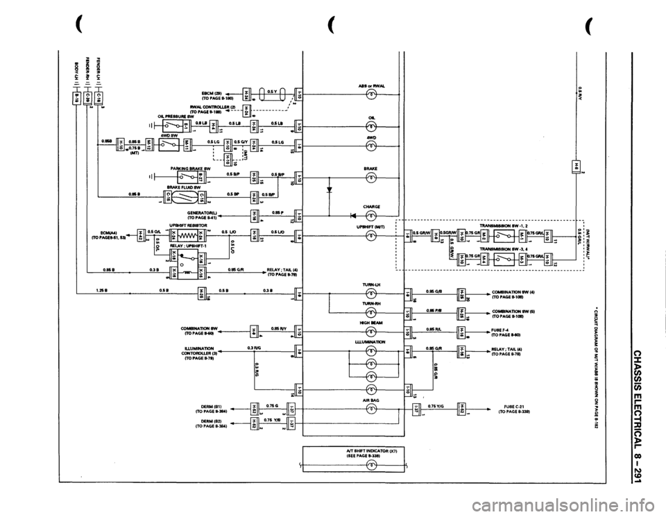
(
I
.. ~ !i:
----
~
........
II
0.858
0.858
0.38
0.85
G/R
1.258
0.58
0.58
0.38
CO-NATIONSW ITOPAGE~
~------_,
cg;c:=~31
0.3 RIG
I
ITO PAGE
8-7S}
:: I~
(
ASS
or RWAL
, • II
OIL ® .awl) ~ -CHARGE
IVT SHIFT
INDICATOR
()(71
{SEE PAGE
11-3351 r:::::-. ~
(
'o .. ~ I J
~~~~
~ ~ ~ '
---------------------------------------------------------
1----
COMBINAliON
8W 1'1
ITO PAGE
11-1011}
1----
CO-NATION
SW(S}
ITO PAGE
11-1011}
~~~~!tEll-SOl ~RELAY;TAILC'I
ITO PAGE
11-78} FUSEC-21 (TO PAGE
8-338}
. n ;;; ~ 0 ~ ;: 3: !il
0
~
::::t
~
)>
)>
(/)
II a;
(/)
..
c;;
~
m
0
r
z
m
... )>
0
~ !
-t ::D
~
c=; )> r co I N CD .....
Page 1524 of 1928
8-334 CHASSIS ELECTRICAL
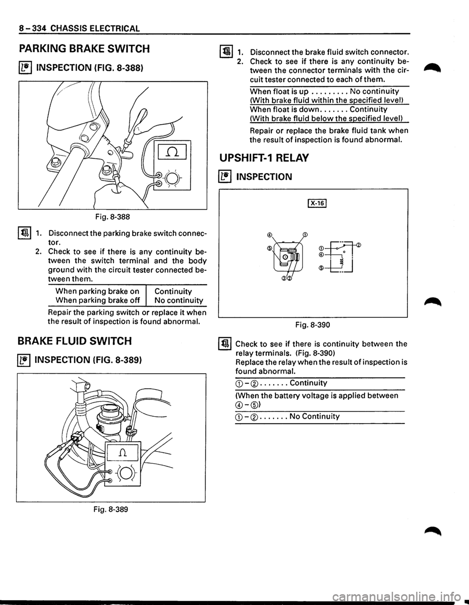
PARKING BRAKE SWITCH
~ INSPECTION (FIG. 8-388)
Fig. 8-388
I ti!!.l 1. Disconnect the parking brake switch connec
tor.
2. Check to see if there is any continuity be
tween the switch terminal and the
body
ground with the circuit tester connected be
tween them.
When parking brake on
Continuity
When parking brake off No continuity
Repair the parking switch
or replace it when
the result
of inspection is found abnormal.
BRAKE FLUID SWITCH
~ INSPECTION (FIG. 8-389)
Fig. 8-389
1311. Disconnectthebrakefluidswitchconnector.
2. Check to see if there is any continuity be-...-...
tween the connector terminals with the cir--..
cuit tester connected to each of them.
When float is up ......... No continuity
(With brake fluid within the specified level)
When float is
down ....... Continuity
(With brake fluid
below the specified level)
Repair
or replace the brake fluid tank when
the result
of inspection is found abnormal.
UPSHIFT-1 RELAY
~ INSPECTION
®ijf ®
-UJ
ill®
Fig. 8-390
131 Check to see if there is continuity between the
relay terminals. (Fig.
8-390)
Replace the relay when the result of inspection is
found abnormal.
G)-® ....... Continuity
(When the battery voltage is applied between
@-@)
G)-® ....... No Continuity
..
Page 1527 of 1928
 I w (0 .....
(
ANTI-THEFT
CONTROLLER
RELAY;
TAIL
RELAY
& FUSE
BOX
\
(FL-
1, FL-2,
F-12)
\"\"
BATIERY
H-41
H-12 H-14
(
STARTERSW
111
1 l
I
I
\V
H-8
B-19
FUSE
B")
'"T1 ce· 0) I w (0 .....
(
ANTI-THEFT
CONTROLLER
RELAY;
TAIL
RELAY
& FUSE
BOX
\
(FL-
1, FL-2,
F-12)
""'
BATIERY
H-41
H-12 H-14
(
STARTERSW
111
1 l
I
I
\V
H-8
B-19
FUSE
BOX
IC-3)
B-12 A/T
SHIFT
INDICOTOR
CONTROL
UNIT
(
~ :a ~ r-0 n ~ -0 2
~ ln (I) c;; m r-·~ ;I ~ 00 I ~ ....
Page 1529 of 1928
'"T1 cO' co w
RELAY
& FUSE
BOX
(FL-11
RELAY:
NC
COMPRESSOR
BLOWER
MOTOR
RELAY:
NCTHERMOSTAT
,,-;~
H-42'
NC:
AIR
CONDITIONING
(
PRESSURE
SW
RECEIVER
DRIER
B-19
FUSE
BOX
(C-19,
C-201
B-36 RELAY;
HEATER
& NC
NCSW FAN
SW
AND
HEATER
BEZEL
ILLUMINATION
LIGHT
(
MAGNETIC
CLUTCH
INC
COMPRESSOR)
;g ::0 ~ r-0 0 ~ 0 2
n :::J: )> en en Cii m rm ~ ::u n )> r-eo I w ~ ...a
Page 1532 of 1928
8-340 CHASSIS ELECTRICAL
HEATER AND AIR CONDITIONING
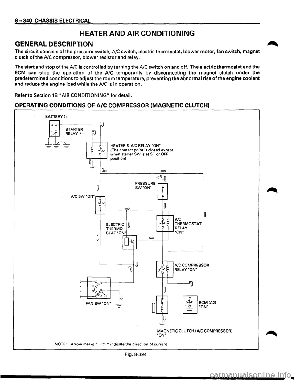
GENERAL DESCRIPTION
The circuit consists of the pressure switch, NC switch, electric thermostat, blower motor, fan switch, magnet
clutch of the NC compressor, blower resistor and relay.
The start and stop of the NC is controlled by turning the NC switch on and off. The electric thermostat and the
ECM can stop the operation of the NC temporarily by disconnecting the magnet clutch under the
predetermined conditions
to adjust the room temperature, preventing the abnormal rise of the engine coolant
and reduce the engine load while the NC is in operation.
Refer
to Section 18 "AIR CONDITIONING" for detail.
OPERATING CONDITIONS OF A/C COMPRESSOR (MAGNETIC CLUTCH)
BATIERY(+)
--
~
A/C SW "ON"
~
HEATER & A/C RELAY "ON"
(The contact point is closed except
when starter SW is at ST or OFF position)
(S =:>
¢:!]
PRESSURE D
SW"ON"
¢:::l
~ FAN SW"ON"
u A/C THERMOSTAT
RELAY
"ON"
A/C COMPRESSOR
RELAY"ON"
ECM IA2l "ON"
MAGNETIC
CLUTCH lAIC COMPRESSOR)
"ON"
NOTE:
Arrow marks" =:> " indicate the direction of current
Fig. 8-394
~
1111
Page 1536 of 1928
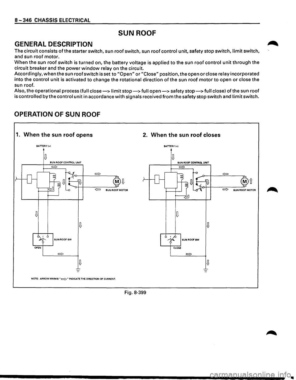
8-346 CHASSIS ELECTRICAL
SUN ROOF
GENERAL DESCRIPTION
The circuit consists of the starter switch, sun roof switch, sun roof control unit, safety stop switch, limit switch,
and sun roof motor.
When the sun
roof switch is turned on, the battery voltage is applied to the sun roof control unit through the
circuit breaker and the power
window relay on the circuit.
Accordingly,
when the sun roof switch is set to "Open" or "Close" position, the open or close relay incorporated
into the control
unit is activated to change the rotational direction of the sun roof motor to open or close the
sun roof.
Also, the operational process (full close-> limit stop-> full open-> safety stop-> full close) ofthe sun roof
is
controlled by the control unit in accordance with signals received from the safety stop switch and limit switch.
OPERATION OF SUN ROOF
1. When the sun roof opens 2. When the sun roof closes
BATTERY(+!
BATTERY(+)
D D SUN ROOF CONTROL UNIT SUN ROO!' CONTIIOI. UNIT
D D
D
D
SUNROOF SW SUNROOFSW
D D
NOTE: ARROW MARKS • =:> • INDICATE THE DIRECTlON 01' CURRENT.
Fig. 8-399
Ill