relay ISUZU TROOPER 1995 Workshop Manual
[x] Cancel search | Manufacturer: ISUZU, Model Year: 1995, Model line: TROOPER, Model: ISUZU TROOPER 1995Pages: 1928
Page 1537 of 1928
"'TI ce· (X) I "" 0 0
(
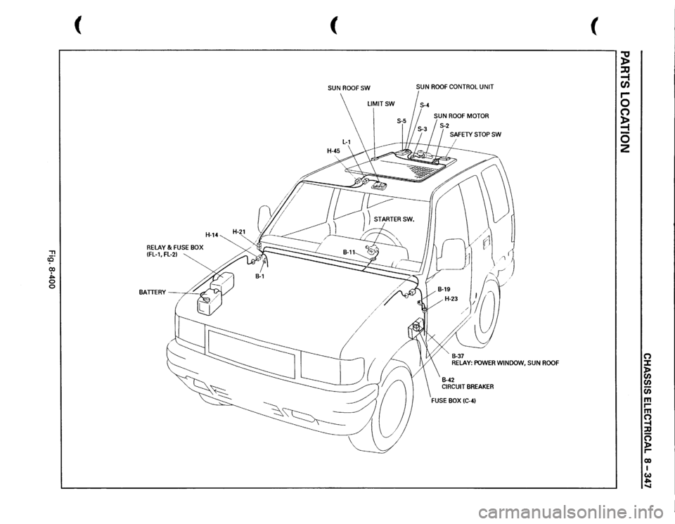
RELAY
& FUSE
BOX
IFL-1,
FL-2)
H-14
BATTERY
' -
,¢_
( SUN
ROOFSW
LIMITSW
SUN
ROOF
CONTROL
UNIT
SAFETY
STOP
SW
I " B-37 RELAY:
POWER
WINDOW,
SUN
ROOF
B-42 CIRCUIT
BREAKER
(
~ ::a -1 en r-0 (") ~ 0 2
0 :I: )> CJ) CJ) c;; m rm ~ ::D ~ r-eo I w .,. -..I
Page 1540 of 1928
8 -350 CHASSIS ELECTRICAL
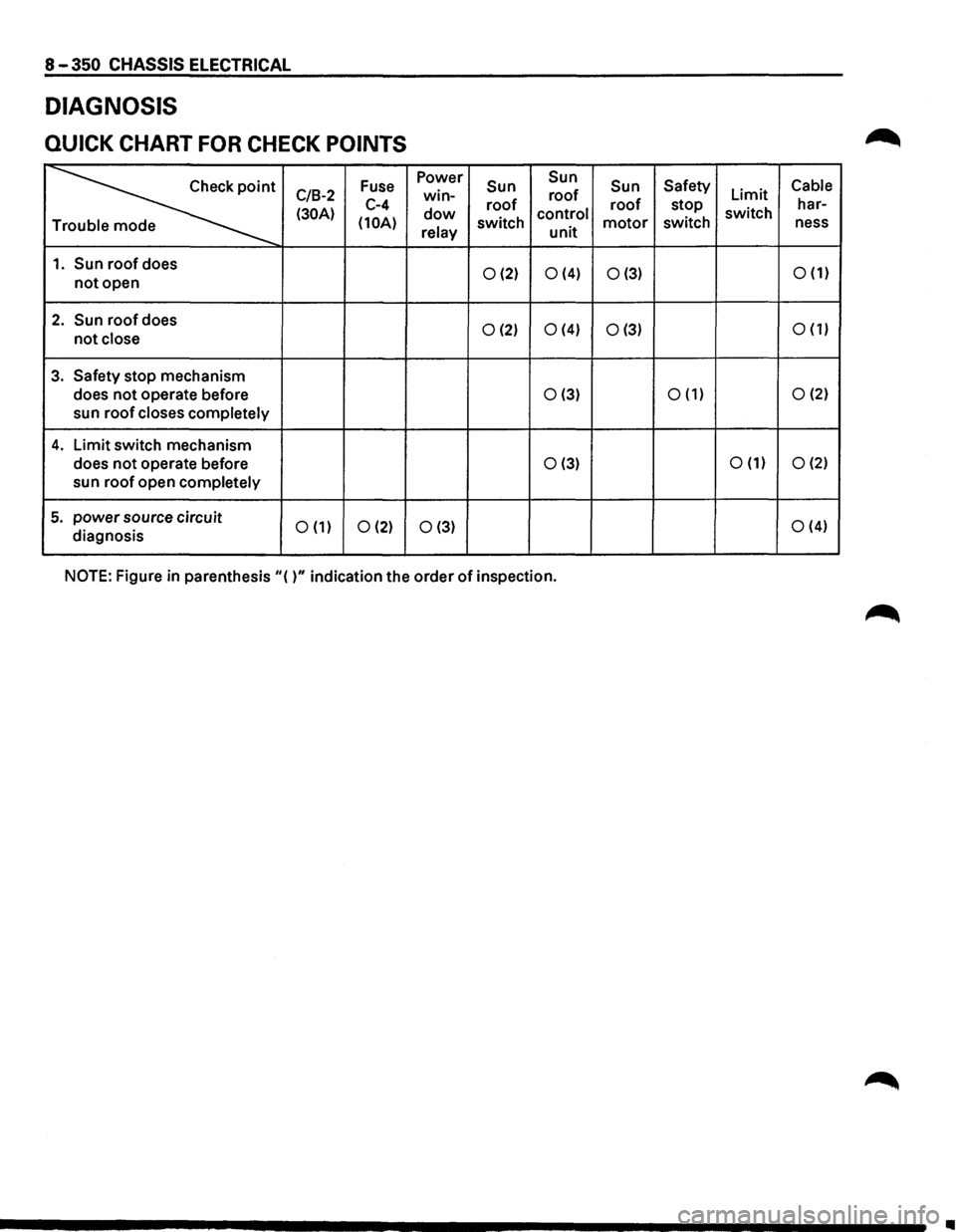
DIAGNOSIS
QUICK CHART FOR CHECK POINTS
~
Fuse Power Sun Sun
Sun Safety Cable
C/B-2 win-roof Limit
(30A) C-4 dow roof control roof stop switch har-
(10A) relay switch unit motor switch
ness T
1. Sun roof does 0 (2) 0 (4) 0 (3) 0 (1) not open
2. Sun roof does 0 (2) 0 (4) 0 (3) 0 (1) not close
3. Safety stop
mechanism
does
not operate before 0(3) 0 (1) 0 (2)
sun roof closes completely
4. Limit switch mechanism
does
not operate before 0 (3) 0 (1) 0 (2)
sun roof open completely
5. power source circuit 0 (1) 0 (2) 0 (3) 0 (4)
diagnosis
NOTE: Figure in parenthesis
"( )" indication the order of inspection.
Ill
Page 1543 of 1928
CHASSIS ELECTRICAL 8-353
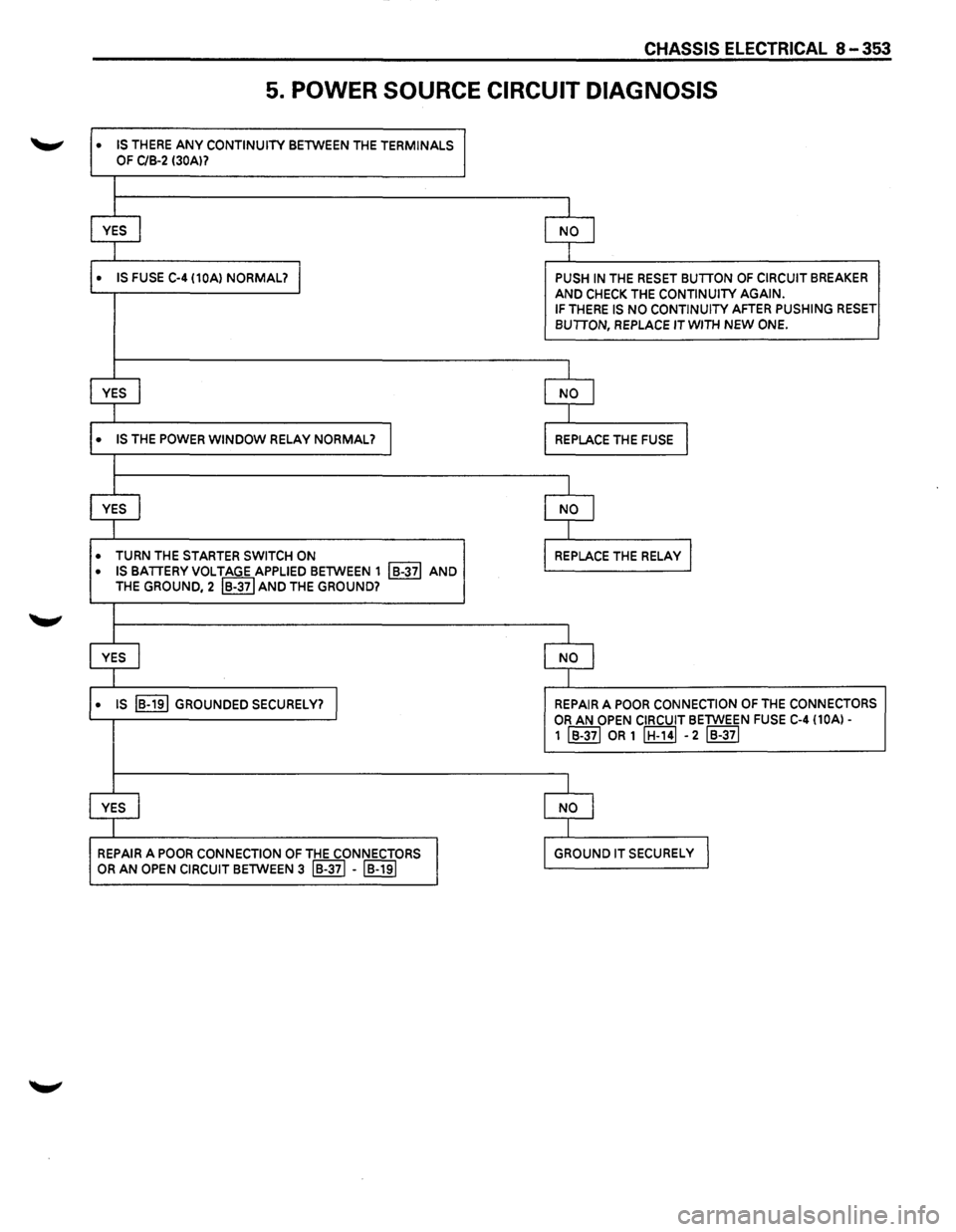
5. POWER SOURCE CIRCUIT DIAGNOSIS
• IS THERE ANY CONTINUITY BETWEEN THE TERMINALS
OF C/B-2 130Al?
I
YES I NO I
I
• IS FUSE C-4 (10Al NORMAL? I PUSH IN THE RESET BUTION OF CIRCUIT BREAKER
AND CHECK THE CONTINUITY AGAIN. IF THERE IS NO CONTINUITY AFTER PUSHING RESET BUTION, REPLACE IT WITH NEW ONE.
I
YES I NO I
I
• IS THE POWER WINDOW RELAY NORMAL? I REPLACE THE FUSE I
I
YES I NO I
I
• TURN THE STARTER SWITCH ON REPLACE THE RELAY I
• IS BATIERY VOLTAGE APPLIED BETWEEN 1 I B-371 AND THE GROUND, 2 IB-371 AND THE GROUND?
1
YES I NO I
I
• IS IB-191 GROUNDED SECURELY? I REPAIR A POOR CONNECTION OF THE CONNECTORS
OR AN OPEN CIRCUIT BETWEEN FUSE C-4 (10A)-
1 IB-371 OR 1 IH-141 -2 IB-371
I
YES I NO I
I
REPAIR A POOR CONNECTION OF THE CONNECTORS GROUND IT SECURELy I
OR AN OPEN CIRCUIT BETWEEN 3 IB-371 -IB-191
Page 1546 of 1928
8-356 CHASSIS ELECTRICAL
SUN ROOF SWITCH
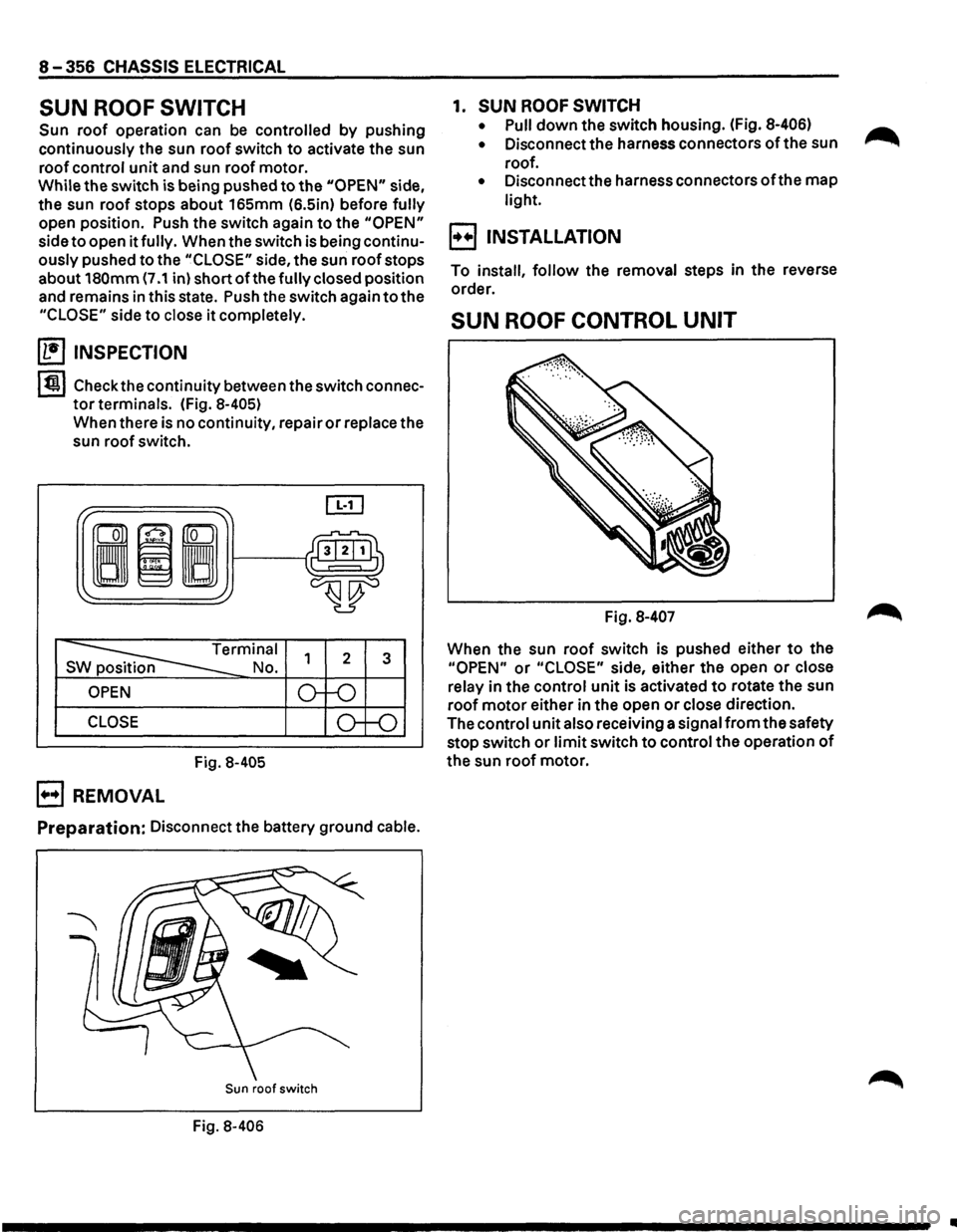
Sun roof operation can be controlled by pushing
continuously the sun
roof switch to activate the sun
roof control
unit and sun roof motor.
While the switch is being pushed
to the "OPEN" side,
the sun roof stops about 165mm (6.5in) before
fully
open position. Push the switch again to the "OPEN"
side to open it fully. When the switch is being continu
ously pushed to the
"CLOSE" side, the sun roof stops
about
180mm (7 .1 in) short ofthe fully closed position
and remains
in this state. Push the switch again to the
"CLOSE" side to close it completely.
~ INSPECTION
I tjt I Check the continuity between the switch connec
tor terminals. (Fig. 8-405)
When there is no continuity, repair or replace the
sun roof switch.
3
CLOSE
Fig. 8-405
E) REMOVAL
Preparation: Disconnect the battery ground cable.
Sun roof switch
Fig. 8-406
1. SUN ROOF SWITCH
• Pull down the switch housing. (Fig. 8-406)
•
Disconnect the harness connectors of the sun
roof.
• Disconnectthe harness connectors ofthe map
light.
E_3 INSTALLATION
To install, follow the removal steps in the reverse
order.
SUN ROOF CONTROL UNIT
Fig. 8-407
When the sun roof switch is pushed either to the
"OPEN" or "CLOSE" side, either the open or close
relay in the control
unit is activated to rotate the sun
roof motor either in the open or close direction.
The control unit also receiving a signal
from the safety
stop switch
or limit switch to control the operation of
the sun roof motor.
Page 1549 of 1928
![ISUZU TROOPER 1995 Workshop Manual SUN ROOF MOTOR
~ INSPECTION
[]1]
I
~rminal
S p No.
Sun roof open side
Sun roof close side
Fig. 8-415 1
2
~ 8
8
~
Apply the battery voltage to the connector terminals
ofthe sun roof mo](/img/61/57183/w960_57183-1548.png "ISUZU TROOPER 1995 Workshop Manual SUN ROOF MOTOR
~ INSPECTION
[]1]
I
~rminal
S p No.
Sun roof open side
Sun roof close side
Fig. 8-415 1
2
~ 8
8
~
Apply the battery voltage to the connector terminals
ofthe sun roof mo")
SUN ROOF MOTOR
~ INSPECTION
[]1]
I
~rminal
S p No.
Sun roof open side
Sun roof close side
Fig. 8-415 1
2
~ 8
8
~
Apply the battery voltage to the connector terminals
ofthe sun roof motor to check its function (Fig. 8-415).
B REMOVAL (FIG. 8-416)
Preparation: Disconnect the battery ground cable.
2. Sun roof motor
1. Headlining
I
Fig.S-416
1. Headlining
• Refer to "Headlining" in Section 10 "Body".
2. Sun roof motor
• Disconnect the connector.
• Remove the three nuts and two screws.
E3 INSTALLATION
To install, follow the removal steps in the reverse
order.
CHASSIS ELECTRICAL 8-359
POWER WINDOW RELAY
(b!] INSPECTION
r·-----,
_..i___/ o----1..4> Q) I I
Fig. 8-417
lt!lll Check to see if there is continuity between the
relay terminals. (Fig. 8-417)
Replace
the relay when the result of inspection is
found abnormal.
®-@ ....... No Continuity
(When the battery voltage is applied between
CD-@)
®-@ ....... Continuity
NOTE:
For the relay removal, refer to "Connector Handling"
in the "NOTES FOR WORKING ON ELECTRICAL
ITEMS"
in this section.
Page 1551 of 1928
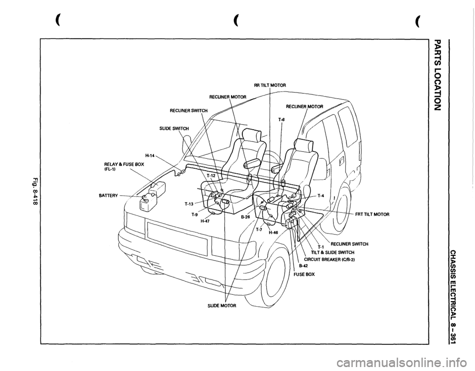
:!! cc 00 I ~ ..... 00
(
RELAY
& FUSE
BOX
(fl-1)
H-14
BATIERY
/
'--#-
(
SLIDE
MOTOR
(
RRTILTMOTOR
FRT
TILT
MOTOR
RECLINER
SWITCH
FUSE
BOX
;g :a ~ r-0 0 ~ 0 z
(') J: ):lo en
en (ii m rm ~ ::D 0 ):lo r-eo I w Q) ~
Page 1565 of 1928
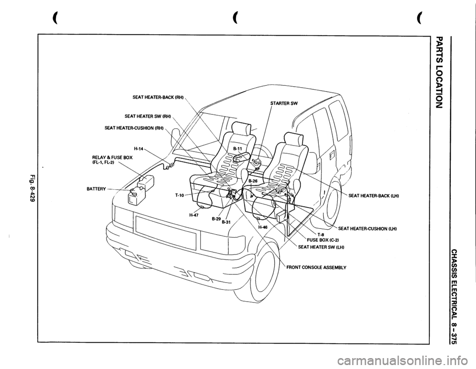
, cE" 00 I ~ ~
SEAT
HEATER·BACK
IRHI,
',
SEAT
HEATER
SW
IRHI
"·
SEAT
HEATER-CUSHION
(RHI
RELAY
& FUSE
BOX
IFL-1,
FL-21
H-14
BATTERY
/ '
#..
(
(
SEAT
HEATER-BACK
ILHI
SEAT
HEATER-CUSHION
(lH)
SEAT
HEATER
SW
ILHI
FRONT
CONSOLE
ASSEMBLY
~ ~ r-0 0 ~ -0 2
n ::t 1: (/) c;; m rm ~ ::D 0 )> r-01) I w ..... C1l
Page 1573 of 1928
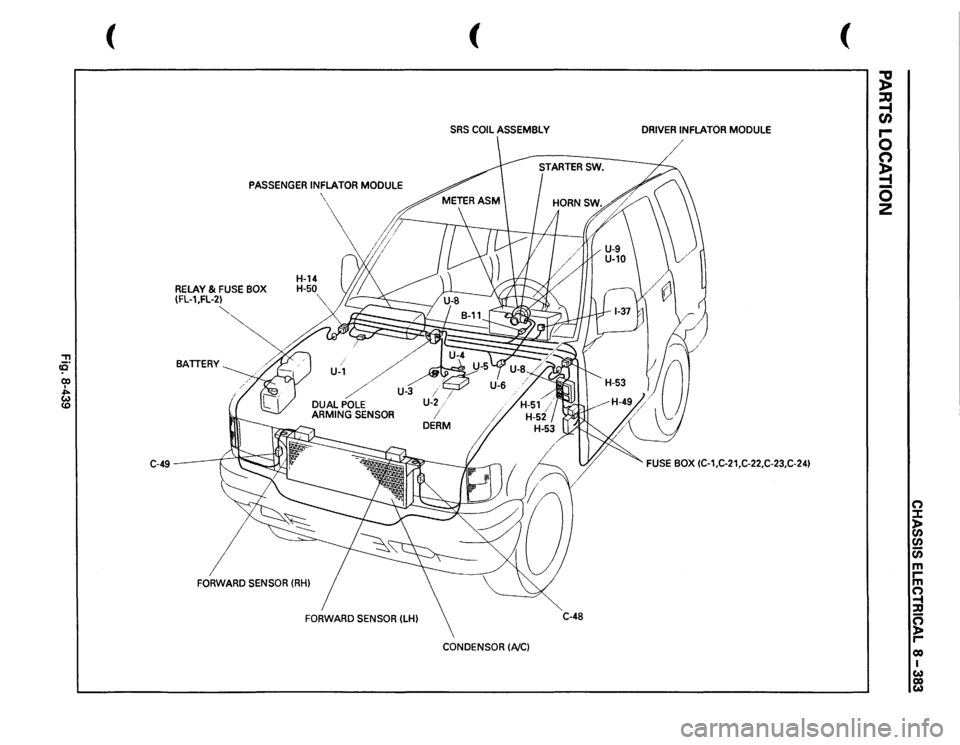
(
PASSENGER
INFLATOR
MODULE
H-14
RELAY
& FUSE
BOX
H-50
(Fl-l,FL-21
"T1 ce·
BATTERY
00 I .J>. ~
C-49
FORWARD
SENSOR
(RHI
FORWARD
SENSOR
(LHI
(
(
SRS
COIL
ASSEMBLY
DRIVER
INFLATOR
MODULE
FUSE
BOX
(C-1,C-21,C-22,C-23,C-241
C-48
CONDENSOR
!NCI
;g ~ r-0 0 ~ -0 2
0 ::t ):lo en
en c;; m rm 0 -t :a ~ r-eo I w co w
Page 1574 of 1928
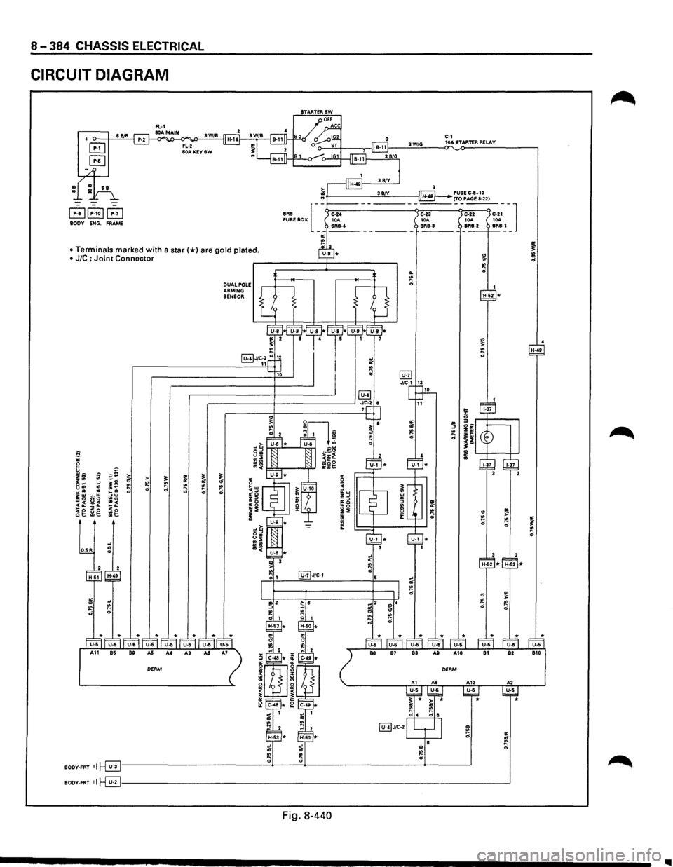
8-384 CHASSIS ELECTRICAL
CIRCUIT DIAGRAM
BODY ENG. FRAME
• Terminals marked with a star(*) are gold plated.
• J/C ; Joint Connector
fi "' 6 ;:-~ ~t; ~ >-t;: ~g " "' u"' ::: .. -~ 0 ,. .. ~: zw _w
"" 0" w., .. t. i:: =:: !(o frl@. ~g cl;
0.15R
~ ~ :e 0
0 ~
~
DUAL POLE ARMING SENSOR
~ " ~
@2)JtC·1
~J/C-2
3W/G
.. "' 0
ID "' 0
C-1 10A STARTER RELAY
BODY-FRT ~~~----------------------------------~~----~----------------------------~--------~
BODY-FRT 11~------------------------------------------------------------------------------------------__J
Fig. 8-440
H-..
•
Page 1585 of 1928
---------------~-~---
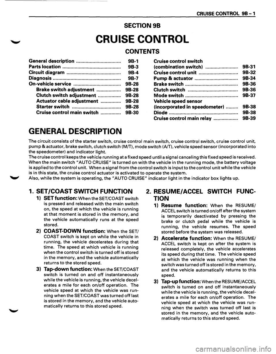
CRUISE CONTROL 9B-1
SECTION 98
CRUISE CONTROL
CONTENTS
General description ................................ .
Parts location .......................................... .
Circuit diagram ....................................... .
Diagnosis ................................................. .
On-vehicle service ................................. ..
Brake switch adjustment ................ ..
Clutch switch adjustment ................ .
Actuator
cable adjustment .............. .
Starter switch ................................... .
Cruise control main switch .............. .
GENERAL DESCRIPTION
98-1
9B-3
98-4
9B-7
98-28
9B-28
9B-28
9B-28
9B-28
9B-30 Cruise
control
switch
(combination switch) ........................ 98-31
Cruise control unit .......................... ... 9B-32
Pump
& actuator .................. .............. 9B-34
Brake switch ....................................... 9B-36
Clutch switch .............................. ....... 9B-36
Mode switch .. .. .. .. .. .. .. .. .. .. .. .. .. .. .. .. .. .. .. . 9B-37
Vehicle speed sensor
(incorporated in speedometer) ......... 9B-38
Diode
.. .. .. .. .. .. . .. .. .. .. .. . .. .. .. .. .. .. .. .. .. .. . .. .. .. 9B-38
Cruise control main relay .................. 9B-39
The circuit consists of the starter switch, cruise control main switch, cruise control switch, cruise control unit,
pump &actuator, brake switch, clutch switch (M/T), mode switch (A/T), vehicle speed sensor (incorporated into
the speedometer) and indicator light.
The cruise control keeps
the vehicle running at a fixed speed until a signal canceling this fixed speed is received.
When the main switch "AUTO CRUISE" is turned on with the vehicle in the running mode, the battery voltage
is applied
to the control unit. When a signal from the control switch is input to the control unit while the vehicle
is in this state, the cruise control actuator is activated to operate the system .
.._, Also, while the system is operating, the "AUTO CRUISE" indicator light in the indicator box lights up.
1. SET /COAST SWITCH FUNCTION
1) SET function: When the SET/COAST switch
is pressed and released
with the main switch
on, the speed at
which the vehicle is running
at that moment is stored in the memory, and
the vehicle
automatically runs at the speed
stored.
2) COAST-DOWN function: When the SET/
COAST switch is kept on while the vehicle in
running, the vehicle decelerates
during that
time. The speed at which vehicle is running
when the control switch is turned off is stored
in the
memory, and the vehicle automatically
returns
to the stored speed.
3) Tap-down function: When the SET/COAST
switch is turned on and off instantaneously
while the vehicle is running, the vehicle decel
erates a mile for each on/off operation. The
vehicle speed at
which the vehicle was run
ning when the SET/COAST was turned off last
is stored in the
memory, and the vehicle auto
matically returns to this stored speed.
2. RESUME/ ACCEL SWITCH FUNC
TION
1) Resume function: When the RESUME/
ACCEL switch is turned
on/off after the system
is
temporarily deactivated by pressing the
brake or clutch pedal while the vehicle is
running,
the vehicle resumes. The speed
stored before the system
was released.
2) Accelerate function: When the RESUME/
ACCEL switch is kept on after the system is
released completely, the vehicle accelerates
its speed
during that time. The vehicle speed
at
which the vehicle was running when the
switch
was turned off is stored in the memory,
and the vehicle automatically returns to this
speed.
3) Tap-up function: When the RESU ME/ACCEL
switch is
turned on and off instantaneously
while the vehicle is running, the vehicle decel
erates a mile for each on/off operation. The
vehicle speed at
which the vehicle was run
ning when the switch was turned off last is
stored in the
memory, and the vehicle auto
matically returns to this stored speed.