check oil ISUZU TROOPER 1995 Workshop Manual
[x] Cancel search | Manufacturer: ISUZU, Model Year: 1995, Model line: TROOPER, Model: ISUZU TROOPER 1995Pages: 1928
Page 5 of 1928
GENERAL INFORMATION OA-1
GENERAL INFORMATION
CONTENTS
General Information ........................................................ /.. . . . . . . . . Section OA / Maintenance and Lubrication ............................................. ~·. . . . . . . . . . . . . Section 08
SECTION OA
GENERAL INFORMATION
CONTENTS
General repair instructions ...................... OA-1 Standard bolts torque
specifications .......... OA-9
How to use this manual. ......................... OA-2 Abbreviations
charts ............................. OA-10
Identification
....................................... OA-5 Service
parts identification plate ............... OA-12
Lifting instructions ................................ OA-7
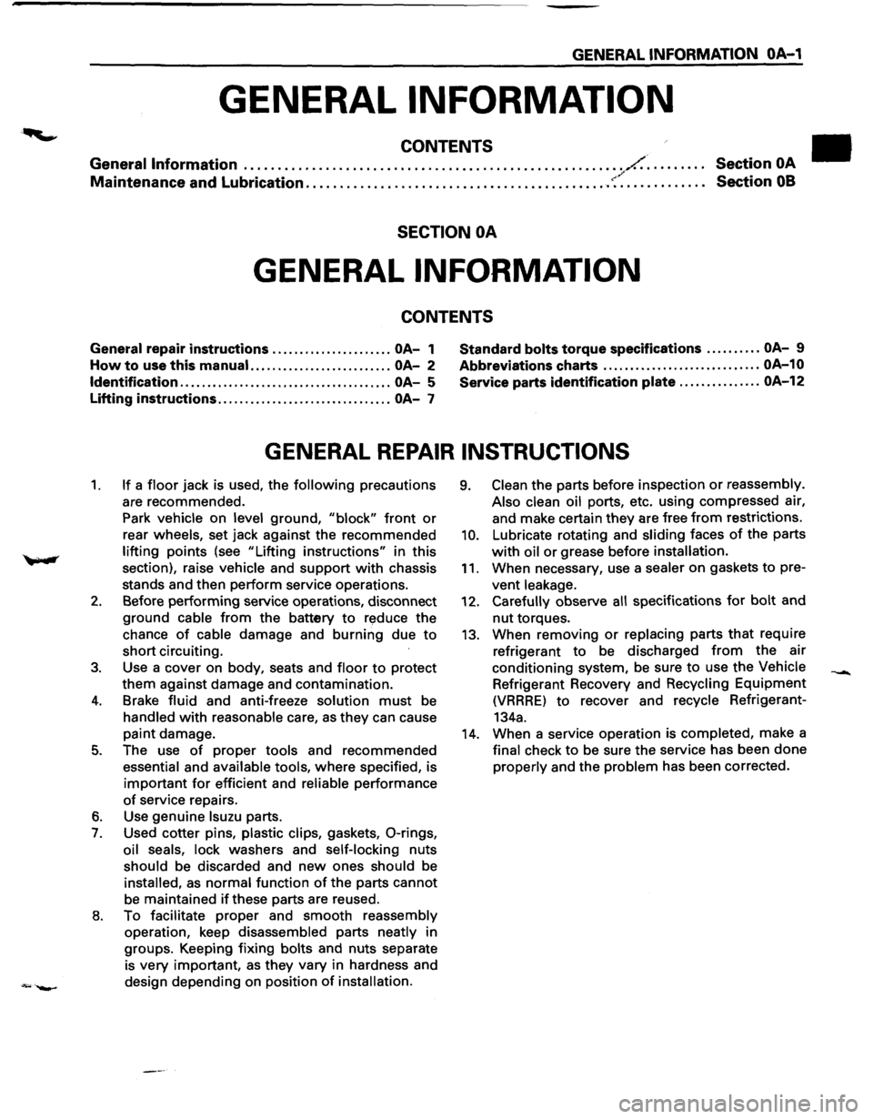
GENERAL REPAIR INSTRUCTIONS
1. If a floor jack is used, the following precautions
are recommended.
Park
vehicle on level ground, "block" front or
rear wheels, set jack against the recommended
lifting points (see "Lifting instructions" in this
section), raise
vehicle and support with chassis
stands and then perform service operations.
2. Before performing service operations, disconnect
ground
cable from the battery to reduce the
chance
of cable damage and burning due to
short circuiting.
3. Use a cover on body, seats and floor to protect
them against damage and contamination.
4. Brake fluid and anti-freeze solution must be
handled with reasonable care, as they can cause
paint damage.
5. The use of proper tools and recommended
essential and available tools, where specified, is
important for efficient and reliable performance
of service repairs.
6. Use genuine lsuzu parts.
7. Used cotter pins, plastic clips, gaskets, 0-rings,
oil seals, lock washers and self-locking nuts
should be discarded and new ones should be
installed, as normal function of the parts cannot
be maintained
if these parts are reused.
8. To facilitate proper and smooth reassembly
operation, keep disassembled parts neatly in
groups. Keeping fixing
bolts and nuts separate
is
very important, as they vary in hardness and
design depending on position
of installation.
9. Clean the parts before inspection or reassembly.
Also clean oil
ports, etc. using compressed air,
and make certain
they are free from restrictions.
10. Lubricate rotating and sliding faces of the parts
with oil or grease before installation.
11. When necessary, use a sealer on gaskets to pre
vent leakage.
12. Carefully observe all specifications for bolt and
nut torques.
13. When removing or replacing parts that require
refrigerant
to be discharged from the air
conditioning system, be sure
to use the Vehicle
Refrigerant Recovery and Recycling Equipment
(VRRRE) to recover and recycle Refrigerant-
134a.
14. When a service operation is completed, make a
final check to be sure the service has been done
properly and the problem has been corrected.
Page 19 of 1928
(
(
(
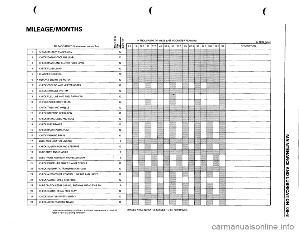
MILEAGE/MONTHS
rn
I ffi
IN THOUSANDS
OF
MILES
(USE
ODOMETER READING)
(x 1000
miles)
~ +~
7.5 15 22.5
30
37.5 45 52.5
60
67.5
75
82.5
90
97.5
105
112.5
120 DESCRIPTION
1
CHECK
BATTERY
FLUID
LEVEL
12
2'-'.:j:
:':
';;;;;
I '' ''
,,,,,,,,,:
[}
2
CHECK
ENGINE
COOLANT
LEVEL
12
':iti:·:
(''''/''?
'';?
,,,,,,,;.;.,.,....
,,,~~
3
CHECK
BRAKE
AND
CLUTCH
FLUID
LEVEL
12
:;:;:;:;:·:·:·.
\::':\' '\"':(\':'''''''''
:'·'·'·:·.,.,,,,
d~~~~~~-------------~
)''
'"''''{''''
'}';;o;o;;
l':':':·:o·.·o·····
4
CHECK
FLUID
LEAKS
12
•.•••..••• ,,......
,,,,,,,,,,,
5
* CHANGE
ENGINE
OIL
12
:.•••:•····
f ) : •
: ; ' {
1:':''''
6
*REPLACE
ENGINE
OIL
FILTER
12
{\::::::::;
[:(o:'.
7
CHECK
COOLING
AND
HEATER
HOSES
12
I : ' :
?
,,,.,,,,,.,:,
.. ;
! • !
•••••••••.
8
CHECK
EXHAUST
SYSTEM
12
I
~
J
:
: ••;·,·····,:·:';';·
•••::::::::::·:;.;
I ;J
., ..... .
9
CHECK
FUEL
LINE
AND
FUEL
TANK/CAP
12
10
CHECK
ENGINE
DRIVE
BELTS
24
. .
I
I
11
CHECKTIRESANDWHEELS
12
li
1:;:~:
}::,
..... ::::, .. ,::,:,:,:,·····
j
12
CHECK
STEERING
OPERATION
12
1
r ., .. ,,.,,.
·
I
13
CHECK
BRAKE
LINES
AND
HOSE
12
~
~
<
.,>
/ ':'??i'
}
J
t
''}{
14
CHECK
DISC
BRAKES
12
10
}}
UL
'I I
•....
15
CHECK
BRAKE
PEDAL
PLAY
12
I"
.. )t
16
CHECK
PARKING
BRAKE
12
li
I
17
LUBE
ACCELERATOR
LINKAGE
6
,,.:
....
I
18
CHECK
SUSPENSION
AND
STEERING
12
••·•••·•··•
19
LUBE
BODY
AND
CHASSIS
6
1''''':'''''''''''
20
LUBE
FRONT
AND
REAR
PROPELLER
SHAFT 6
{:
!: • :•••••l
21
CHECK
PROPELLER
SHAFT FLANGE
TORQUE
12
•
22
*CHECK AUTOMATIC TRANSMISSION
FLUID
12
... ,, ,....
@{I{
,,,,,,,,
ttJ
·~+---------------!
23
CHECK
AUTO
CRUISE
CONTROL
LINKAGE
AND
HOSES
12
~ .
:l
!•••:
24
CHECK
CLUTCH
LINES
AND
HOSE
12
25
LUBE
CLUTCH
PEDAL
SPRING,
BUSHING
AND
CLEVIS
PIN
6
l':":"·:"ii
26
CHECK
CLUTCH
PEDAL
FREE
PLAY
12
1/JJ(
21
cHEcK sTARTER SAFETY swiTCH 12
1/,,,,.,,,,,,,,,
,,,,,,,,,
-~~~--~~~~~~-~~~~~[============J
28
CHECK
ACCELERATOR
LINKAGE
12
m ::::::::]
!•'····
'.!
Under
severe driving conditions,
additional
maintenance
is required.
Refer to
"Severe
driving
conditions".
SHADED AREA
INDICATES
SERVICE
TO
BE PERFORMED.
s: ~ 2 -1 m 2 )> 2 n m )> 2 c rc m ::u n ~ 0 2 Q ~
Page 21 of 1928
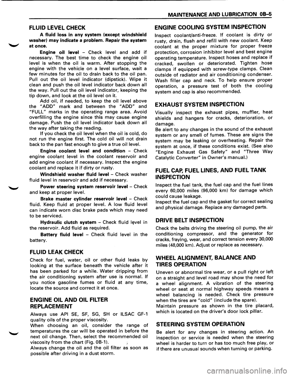
FLUID LEVEL CHECK
A fluid loss in any system (except windshield
washer) may indicate a problem. Repair the system
at once.
Engine
oil level -Check level and add if
necessary. The best time to check the engine oil
level is
when the oil is warm. After stopping the
engine with the vehicle on a level surface, wait a
few minutes for the oil to drain back to the oil pan.
Pull
out the oil level indicator (dipstick). Wipe it
clean and push the oil level indicator back down all
the
way. Pull out the oil level indicator, keeping the
tip down, and look at the oil level on it.
Add oil, if needed, to keep the oil level above
the
"ADD" mark and between the "ADD" and
"FULL" marks in the operating range area. Avoid
overfilling the engine since this may cause engine
damage. Push
the oil level indicator back down all
the
way after taking the reading.
If you check the oil level when the oil is cold, do
not run the engine first. The cold oil will not drain
back
to the pan fast enough to give a true oil level.
Engine coolant level and condition -Check
engine coolant level in the coolant reservoir and
add engine
coolant if necessary. Inspect the engine
coolant and replace it if dirty or rusty.
Windshield washer fluid level -Check washer
fluid level in reservoir and add if necessary.
Power steering system reservoir level-Check
and keep at
proper level.
Brake master cylinder reservoir level -Check
fluid. Keep fluid at proper level. A low fluid level
can indicate
worn disc brake pads which may need
to be serviced.
Hydraulic clutch system -Check fluid l~vel in
the reservoir.
Add fluid as required.
Battery fluid level -Check fluid level in the
battery.
FLUID LEAK CHECK
Check for fuel, water, oil or other fluid leaks by
looking at the surface beneath the vehicle after it
has been parked for a while. Water dripping from
the air conditioning system after use is normal. If
you notice gasoline fumes or fluid at any time,
locate the source and correct it at once.
ENGINE OIL AND OIL FILTER
REPLACEMENT
Always use API SE, SF, SG, SH or ILSAC GF-1
quality oils of the proper viscosity.
When choosing an oil, consider the range of
temperatures the car will be operated in before the
next oil change. Then, select the recommended oil
viscosity
from the chart (Fig. OB-1).
Always change the oil and the oil filter as soon as
possible after driving in a dust storm.
MAINTENANCE AND LUBRICATION OB-5
ENGINE COOLING SYSTEM INSPECTION
Inspect coolant/anti-freeze. If coolant is dirty or
rusty, drain, flush and refill with new coolant. Keep
coolant at the proper mixture for proper freeze
protection,
corrosion inhibitor level and best engine
operating temperature.
Inspect hoses and replace if
cracked, swollen or deteriorated. Tighten hose
clamps if equipped with screw-type clamps. Clean
outside of radiator and air conditioning condenser.
Wash
filler cap and neck. To help ensure proper
operation, a pressure test of both the cooling
system and cap is also recommended.
EXHAUST SYSTEM INSPECTION
Visually inspect the exhaust pipes, muffler, heat
shields and hangers
for cracks, deterioration, or
damage.
Be alert to any changes in the sound of the exhaust
system
or any smell of fumes. These are signs the
system may be leaking or overheating. Repair the
system at once,
if these conditions exist. (See also
"Engine Exhaust Gas Safety" and "Three Way
Catalytic Converter" in Owner's manual.)
FUEL CAP, FUEL LINES, AND FUEL TANK
INSPECTION
Inspect the fuel tank, the fuel cap and the fuel lines
every
60,000 miles (96,000 km) for damage which
could cause leakage.
Inspect the fuel cap and the gasket for correct sealing
and physical damage. Replace any damaged parts.
DRIVE BELT INSPECTION
Check the belts driving the steering oil pump, the air
conditioning compressor, and the generator
for
cracks, fraying, wear, and correct tension every 30,000
miles (48,000 km). Adjust or replace as necessary.
WHEEL ALIGNMENT, BALANCE AND
TIRES OPERATION
Uneven or abnormal tire wear, or a pull right or left
on a straight and level road may show the need for
a wheel alignment. A vibration of the steering
wheel or seat at normal highway speeds means a
wheel balancing is needed. Check tire pressure
when the tires are "cold" (include the spare).
Maintain pressure as shown in the tire placard,
which is located on the driver's door lock pillar.
STEERING SYSTEM OPERATION
Be alert for any changes in steering action. An
inspection
or service is needed when the steering
wheel is harder
to turn or has too much free play, or
if there are unusual sounds when turning or parking.
Page 29 of 1928
MAINTENANCE AND LUBRICATION OB-13
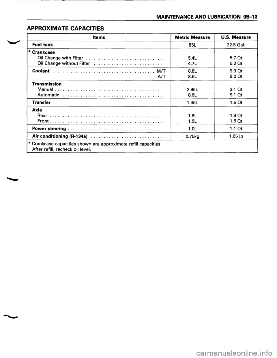
APPROXIMATE CAPACITIES
Items Metric Measure U.S. Measure
Fuel tank 85L 22.5 Gal.
*Crankcase
Oil Change with Filter .............................. 5.4L 5.7 at
Oil Change without Filter ••••••••••••••••••\
0 •••• 0 ••• 4.7L
5.0 at
Coolant ........................................ MIT 8.8L 9.3 at
A/T 8.5L 9.0 at
Transmission
Manual
.......................................... 2.95L 3.1 at
Automatic ••••••••••••••••••\
•• 0 •••• 0 0 0 ••••••••••• 8.6L 9.1 at
Transfer
1.45L 1.5 at
Axle
Rear o o o 0
0 0 0 0 0 0 0 0 0 0 0 0 0 0 0 0 I 0 0 0 o o o o o o o 0 0 0 0 0 0 0 0 0 0 0 o o 1.8L 1.9 at
Front ........................................ ~ ... 1.5L 1.6 at
Power steering ••• 0 ••••••••• 0 ••••••••••••••••••\
0 •••• 1.0L 1.1 at
Air conditioning (R-134a) o o 0
0 0 0 0 0 0 0 0 I 0 0 0 0 0 o o 0 o 0 0 0 0 0 0 0 0.75kg 1.651b
* Crankcase capacities shown are approximate refill capacities.
After
refill, recheck oil level.
Page 63 of 1928
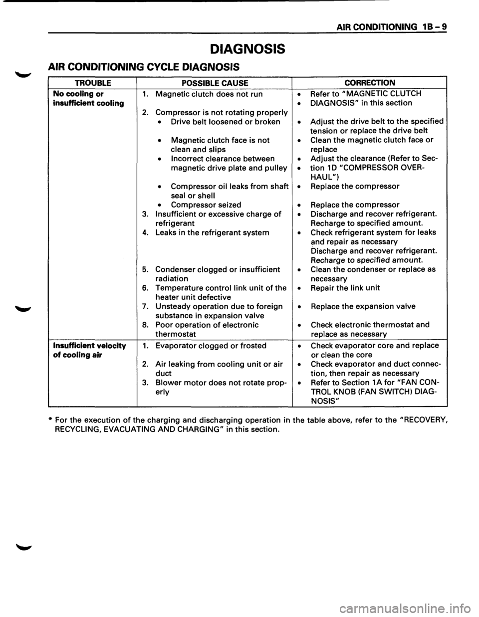
DIAGNOSIS
AIR CONDITIONING CYCLE DIAGNOSIS
TROUBLE POSSIBLE CAUSE
No cooling or 1. Magnetic clutch does not run
insufficient cooling
2. Compressor is not rotating properly
• Drive belt loosened or broken
• Magnetic clutch face is not
clean and slips
• Incorrect clearance between
magnetic
drive plate and pulley
• Compressor oil leaks from shaft
seal
or shell
• Compressor seized
3. Insufficient or excessive charge of
refrigerant
4. Leaks in the refrigerant system
5. Condenser clogged or insufficient
radiation
6. Temperature control link unit of the
heater
unit defective
7. Unsteady operation due to foreign
substance in expansion valve
8. Poor operation of electronic
thermostat
Insufficient velocity 1. Evaporator clogged or frosted
of cooling air
2. Air leaking from cooling unit or air
duct
3. Blower motor does not rotate prop-
erly
AIR CONDITIONING 1 B - 9
CORRECTION
• Refer to "MAGNETIC CLUTCH
• DIAGNOSIS" in this section
• Adjust the drive belt to the specified
tension
or replace the drive belt
• Clean the magnetic clutch face or
replace
• Adjust the clearance (Refer to Sec-
• tion 1 D "COMPRESSOR OVER-
HAUL")
• Replace the compressor
• Replace the compressor
• Discharge and recover refrigerant.
Recharge
to specified amount.
• Check refrigerant system for leaks
and repair
as necessary
Discharge and recover refrigerant.
Recharge
to specified amount.
• Clean the condenser or replace as
necessary
• Repair the link unit
• Replace the expansion valve
• Check electronic thermostat and
replace
as necessary
• Check evaporator core and replace
or clean the core
• Check evaporator and duct connec-
tion, then repair as necessary
• Refer to Section 1A for "FAN CON-
TROL KNOB
(FAN SWITCH) DIAG-
NOSIS"
* For the execution of the charging and discharging operation in the table above, refer to the "RECOVERY,
RECYCLING, EVACUATING
AND CHARGING" in this section.
Page 73 of 1928
AIR CONDITIONING 1 B -19
ON-VEHICLE SERVICE
GENERAL REPAIR PROCEDURE
Precautions for Replacement or Repair of Air
Conditioning Parts
There are certain procedures, practices and pre
cautions
that should be followed when servicing air
conditioning systems:
• Keep your work area clean.
•
Always wear safety goggle and protective gloves
when working on refrigerant systems.
• Beware of the danger of carbon monoxide fumes
caused by running the engine.
• Beware of discharged refrigerant in enclosed or
improperly ventilated garages.
• Always disconnect the negative battery cable and
discharge and recover the refrigerant
whenever
repairing the air conditioning system.
• When discharging and recovering the refrigerant,
do not allow refrigerant to discharge too fast; it
will draw compressor oil out of the system.
• Keep moisture and contaminants out of the sys
tem.
When disconnecting or removing any lines
or parts, use plugs or caps to close the fittings
immediately.
Never remove the caps or plugs until the lines or
parts are reconnected or installed.
•
When disconnecting or reconnecting the lines,
use
two wrenches to support the line fitting, to
prevent from twisting or other damage.
• Always install new 0-rings whenever a connec
tion is disassembled.
• Before connecting any hoses or lines, apply new
specified compressor oil to the 0-rings.
• When removing and replacing any parts which
require discharging the refrigerant circuit, the
operations described in
this section must be per
formed in the following sequence:
1. Use the J-39500 (ACR4
: HFC-134a Refrigerant
Recovery/Recycling/Recharging/System)
or
equivalent to thoroughly discharge and re
cover
the refrigerant.
2. Remove and replace the defective part.
3.
After evacuation, charge the air conditioning
system and check for leaks.
Repair of Refrigerant Leaks
Refrigerant Line Connections
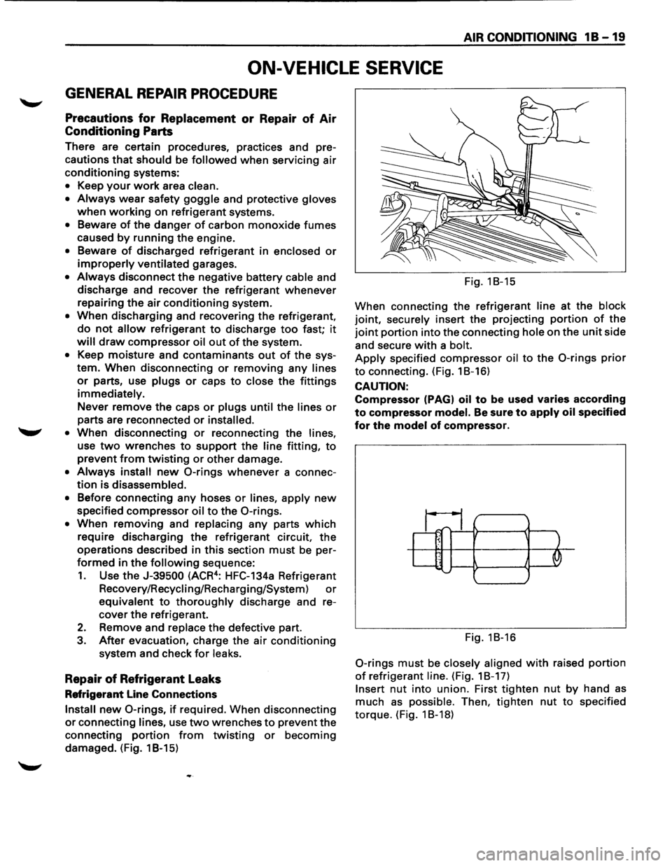
Install new 0-rings, if required. When disconnecting
or connecting lines, use two wrenches to prevent the
connecting
portion from twisting or becoming
damaged. (Fig. 1 B-15) Fig.
18-15
When connecting the refrigerant
line at the block
joint, securely insert the projecting portion of the
joint portion into the connecting hole on the unit side
and secure
with a bolt.
Apply specified compressor oil to the 0-rings prior
to connecting. (Fig. 18-16)
CAUTION:
Compressor (PAGI oil to be used varies according
to compressor model. Be sure to apply oil specified
for the model of compressor.
~1;1_ ~ ' .. J '--......
Fig. 18-16
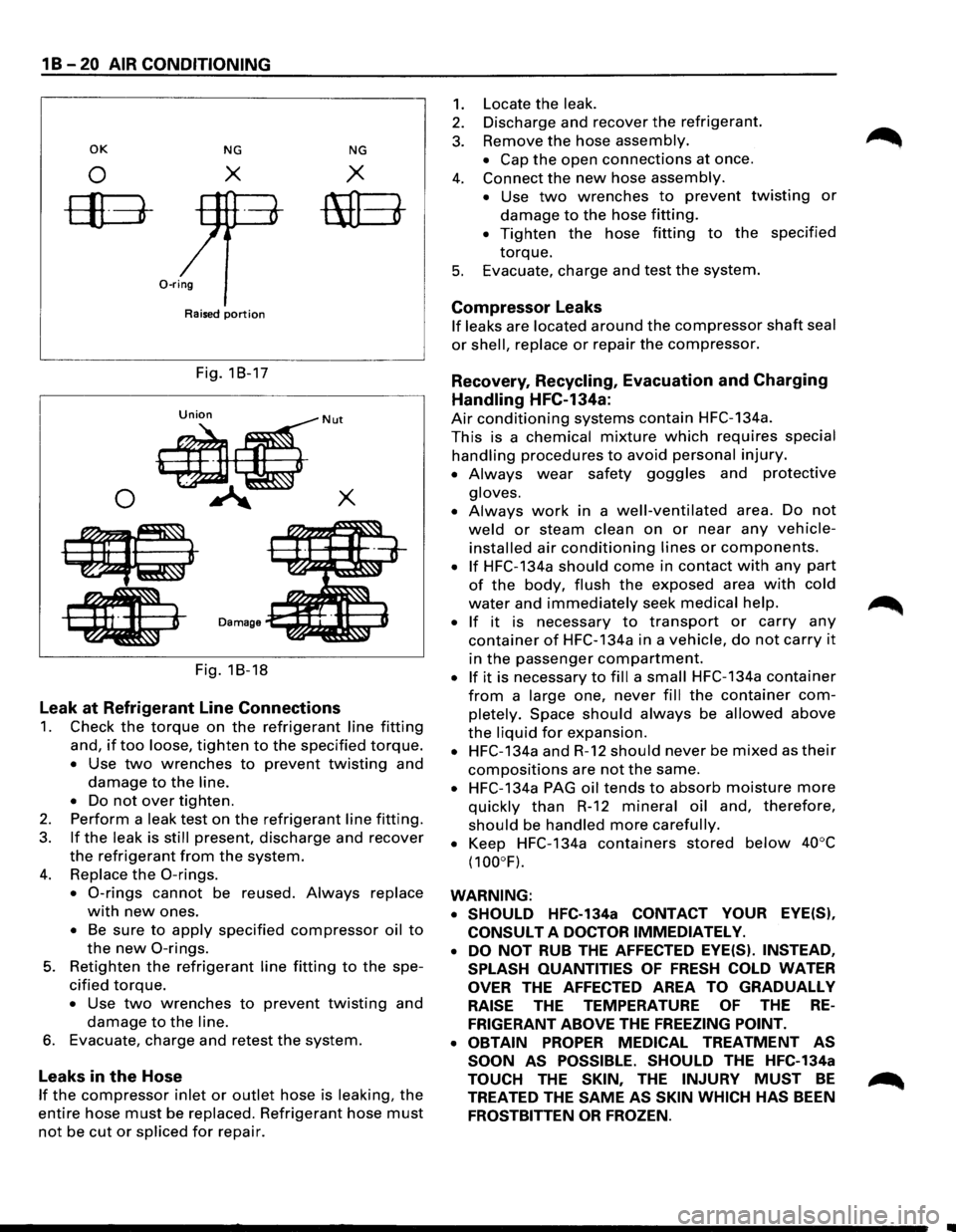
0-rings must be closely aligned with raised portion
of refrigerant line. (Fig. 18-17)
Insert nut into union. First tighten nut by hand as
much as possible. Then, tighten nut to specified
torque. (Fig. 1 8-18)
Page 74 of 1928
1 B -20 AIR CONDITIONING
OK NG NG
0 X X
ffB-mEt
0-ring
Raised portion
Fig. 18-17
0
Fig. 18-18
Leak at Refrigerant Line Connections
1. Check the torque on the refrigerant line fitting
and, if too loose, tighten to the specified torque.
• Use two wrenches to prevent twisting and
damage to the line.
•
Do not over tighten.
2. Perform a leak test on the refrigerant line fitting.
3. If the leak is still present, discharge and recover
the refrigerant from the system.
4. Replace the 0-rings.
• 0-rings cannot be reused. Always replace
with new ones.
• Be sure to apply specified compressor oil to
the new 0-rings.
5. Retighten the refrigerant line fitting to the spe
cified torque.
• Use two wrenches to prevent twisting and
damage to the line.
6. Evacuate, charge and retest the system.
Leaks in the Hose
If the compressor inlet or outlet hose is leaking, the
entire hose must be replaced. Refrigerant hose must
not be cut or spliced for repair.
1.
2.
3.
4.
5.
Locate the leak.
Discharge and recover the refrigerant.
Remove
the hose assembly.
• Cap the open connections at once.
Connect
the new hose assembly.
•
Use two wrenches to prevent twisting or
damage to the hose fitting.
• Tighten the hose fitting to the specified
torque.
Evacuate, charge and test the system.
Compressor Leaks
If leaks are located around the compressor shaft seal
or shell, replace or repair the compressor.
Recovery, Recycling, Evacuation and Charging
Handling HFC-134a:
Air conditioning systems contain HFC-134a.
This is a chemical mixture which requires special
handling procedures to avoid personal injury.
• Always wear safety goggles and protective
gloves.
•
Always work in a well-ventilated area. Do not
weld or steam clean on or near any vehicle
installed air conditioning lines or components.
• If HFC-134a should come in contact with any part
of the body, flush the exposed area with cold
water and immediately seek medical help.
•
If it is necessary to transport or carry any
container of HFC-134a in a vehicle, do not carry it
in the passenger compartment.
• If it is necessary to fill a small HFC-134a container
from a large one, never fill the container com
pletely. Space should always be allowed above
the liquid for expansion.
• HFC-134a and R-12 should never be mixed as their
compositions are not the same.
• HFC-134a PAG oil tends to absorb moisture more
quickly than R-12 mineral oil and, therefore,
should be handled more carefully.
•
Keep HFC-134a containers stored below 40°C
(100°F).
WARNING: • SHOULD
HFC-134a CONTACT YOUR EYE(S),
CONSULT
A DOCTOR IMMEDIATELY.
•
DO NOT RUB THE AFFECTED EYE(S). INSTEAD,
SPLASH QUANTITIES
OF FRESH COLD WATER
OVER THE AFFECTED AREA TO GRADUALLY
RAISE THE TEMPERATURE OF THE RE
FRIGERANT ABOVE THE FREEZING POINT.
• OBTAIN
PROPER MEDICAL TREATMENT AS
SOON
AS POSSIBLE. SHOULD THE HFC-134a
TOUCH THE SKIN, THE INJURY MUST BE
TREATED THE SAME AS SKIN WHICH HAS BEEN
FROSTBITTEN OR FROZEN.
Page 81 of 1928
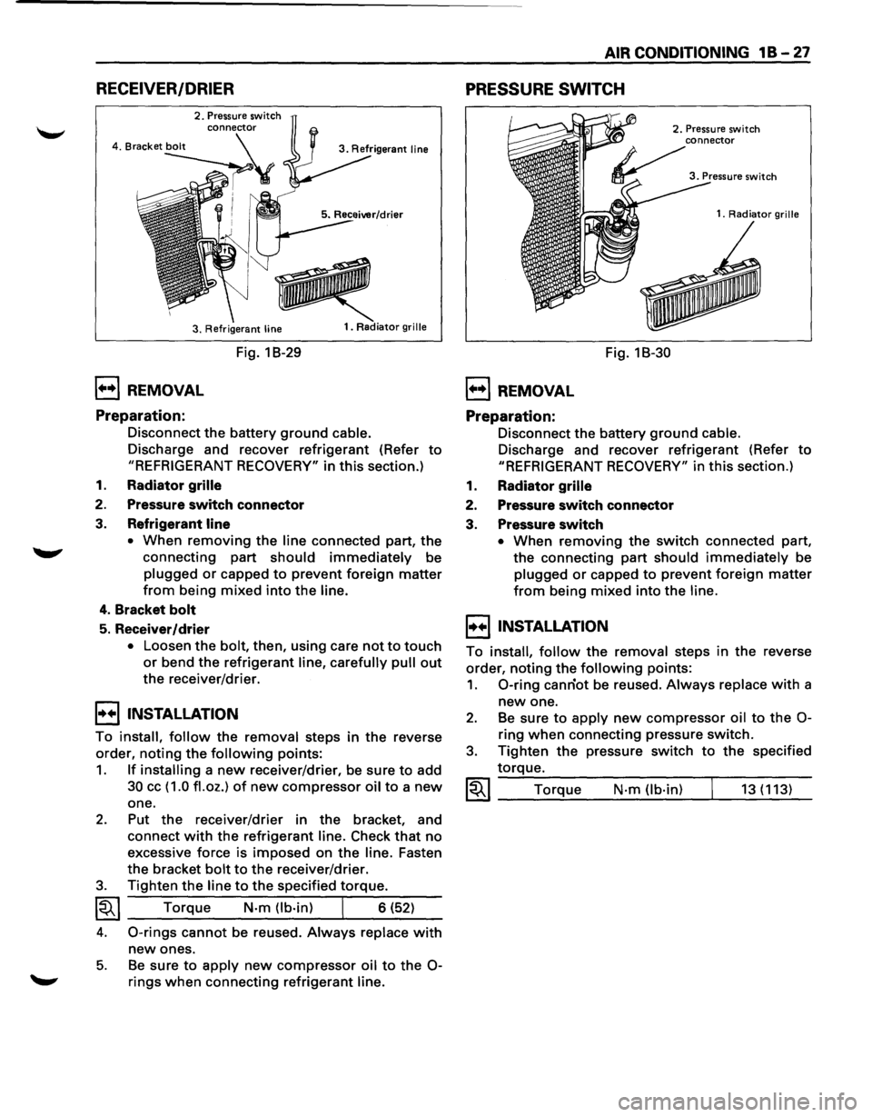
RECEIVER/DRIER
2. Pressure switch
3. Refrigerant
line
1••1 REMOVAL
Preparation:
Fig. 1 B-29
1. Radiator grille
Disconnect the battery ground cable.
Discharge and recover refrigerant (Refer to
"REFRIGERANT RECOVERY" in this section.)
1. Radiator grille
2. Pressure switch connector
3. Refrigerant line
•
When removing the line connected part, the
connecting part
should immediately be
plugged or capped to prevent foreign matter
from being mixed into the line.
4. Bracket bolt
5. Receiver/drier
• Loosen the bolt, then, using care not to touch
or bend the refrigerant line, carefully pull out
the receiver/drier.
I••I•NSTALLATION
To install, follow the removal steps in the reverse
order,
noting the following points:
1. If installing a new receiver/drier, be sure to add
30 cc ( 1.0 fl. oz.) of new compressor oil to a new
one.
2. Put the receiver/drier in the bracket, and
connect
with the refrigerant line. Check that no
excessive force is imposed on the line. Fasten
the bracket
bolt to the receiver/drier.
3. Tighten the line to the specified torque.
~~~ Torque N-m (lb-in) I 6 (52)
4. 0-rings cannot be reused. Always replace with
new ones.
5. Be sure to apply new compressor oil to the 0-
rings when connecting refrigerant line.
AIR CONDITIONING 1 B -27
PRESSURE SWITCH
1••1 REMOVAL
Preparation:
Fig. 18-30
2. Pressure switch
1.
Radiator grille
Disconnect the battery ground cable.
Discharge and recover refrigerant (Refer to
"REFRIGERANT RECOVERY" in this section.)
1. Radiator grille
2. Pressure switch connector
3. Pressure switch
• When removing the switch connected part,
the connecting
part should immediately be
plugged or capped to prevent foreign matter
from being mixed into the line.
I••IINSTALLATION
To install, follow the removal steps in the reverse
order,
noting the following points:
1. 0-ring canriot be reused. Always replace with a
new one.
2. Be sure to apply new compressor oil to the 0-
ring when connecting pressure switch.
3. Tighten the pressure switch to the specified
torque.
~~~ Torque N·m (lb-in) 13 (113)
Page 89 of 1928
COMPRESSOR OVERHAUL 1 D - 1
SECTION 10
COMPRESSOR OVERHAUL
CONTENTS
General Description . . . . . . . . . . . . . . . . . . . . . 1 D-1
Diagnosis . . . . . . . . . . . . . . . . . . . . . . . . . . . . . 1
D-2
General Information . . . . . . . . . . . . . . . . . . . . 1 D-3
Compressor Oil . . . . . . . . . . . . . . . . . . . . . . 1 D-3
Service Procedures . . . . . . . . . . . . . . . . . . . . . 1D-5
Magnetic Clutch Assembly . . . . . . . . . . . . . 1 D-5
Main Data and Specifications . . . . . . . . . . . . . 1 D-8
General Specifications . . . . . . . . . . . . . . . . . 1 D-8
Torque Specifications . . . . . . . . . . . . . . . . . 1 D-8
Special Tools . . . . . . . . . . . . . . . . . . . . . . . . . . 1D-9
GENERAL DESCRIPTION
When servicing the compressor, keep dirt or foreign
material from getting on or into the compressor
parts and system. Clean tools and a clean work area
are
important for proper service. The compressor
connections and the outside of the compressor
should be cleaned before any "On-Vehicle" repair,
or before removal of the compressor. The parts must
be kept clean at all times and any parts to be
reassembled
should be cleaned with Trichloro
ethane, naphtha, kerosene, or equivalent solvent,
and
dried with dry air. Use only lint free cloths to
wipe parts.
The
operations described below are based on bench
overhaul
with compressor removed from the
vehicle, except as noted. They have been prepared
in
order of accessibility of the components. When
the compressor is removed from the vehicle for
servicing, the oil remaining in the compressor
should be discarded and new compressor oil added
to the compressor.
Magnetic clutch assembly repair procedures require
that the system be discharged of refrigerant. (Refer
to Section 1 B for "REFRIGERANT RECOVERY".)
Compressor malfunction will appear in one of four
ways: noise, seizure, leakage or low discharge
pressure. Resonant
compressor noises are not
cause for alarm; however, irregular noise or rattles
may indicate broken parts or excessive clearances
due to wear. To check seizure, de-energize the
magnetic clutch and check to see if the drive plate
can be rotated.
If rotation is impossible, the com
pressor is seized. Low discharge pressure may be
due to a faulty internal seal of the compressor, or a
restriction in the compressor.
Low discharge pres
sure
may also be due to an insufficient refrigerant
charge
or a restriction elsewhere in the system.
These possibilities
should be checked prior to
servicing the compressor. If the compressor is
inoperative,
but is not seized, check to see if current
is being supplied to the magnetic clutch coil
terminals.
This vehicle is equipped with five-vane rotary com
pressor.
The
compressor has vanes built into a rotor which is
mounted on a shaft.
When the shaft rotates, the vanes built into the
cylinder block assembly are opened by centrifugal
force.
This changes the volume of the space formed by the
rotor and cylinder, resulting in the intake and
compression of the refrigerant gas. The discharge
valve and the
valve stopper, which protects the
discharge valve, are
built into the cylinder block
assembly. There is no suction valve but a shaft seal
is
installed between the shaft and head; a trigger
valve, which applies back pressure to the vanes, is
installed in the cylinder block and a refrigerant gas
temperature sensor is installed in the front head.
The specified
quantity of compressor oil is contained
in
the compressor to lubricate the various parts
using
the refrigerant gas discharge pressure.
The thermo sensor is installed to the front head of
the compressor to protect it by stopping its
operation when the refrigerant gas is insufficient or
when the temperature get abnormally high.
•OFF ..... 160 ±soc (320.0 ± 9.0°F)
•ON ..... 135 ±soc (275.0 ± 9.0°F)
The oil used in the HFC-134a system compressor
differs from that used in R-12 systems.
Also, compressor
oil to be used varies according to
the compressor model. Be sure to avoid mixing two
or more different types of oil.
If the wrong oil is used, lubrication will be poor and
the compressor will seize or malfunction.
The specified
amount of the compressor oil is
150cc (5.0 fl.oz.).
Page 91 of 1928
COMPRESSOR OVERHAUL 10-3
GENERAL INFORMATION
COMPRESSOR OIL
OIL SPECIFICATION
• The HFC-134a system requires a synthetic
(PAG) compressor oil whereas the R-12 system
requires a
mineral compressor oil. The two oils
must never be mixed.
• Compressor (PAG) oil varies according to com
pressor model. Be sure to use oil specified for
the model of compressor.
• Always use HFC-134a Vane Rotary Type Com
pressor Oil
(AIPDN Part No. 2-90188-301-0)
HANDLING OF OIL
• The oil should be free from moisture, dust,
metal powder, etc.
• Do not mix with other oil.
•
The water content in the oil increases when
exposed to the air. After use, seal oil from air
immediately.
(HFC-134a Vane Rotary Compressor Oil absorbs
moisture very easily.)
•
The compressor oil must be stored in steel
containers, not in plastic containers.
COMPRESSOR OIL CHECK
The oil used to lubricate the compressor is circul
ating with the refrigerant.
Whenever replacing any component of the system
or a large amount of gas leakage occurs, add oil to
maintain the original amount of oil.
Oil Capacity.
Capacity
total in system 150cc (5.0 fl.oz.)
Compressor (Service
parts)
charging amount 15 0cc (5
·0
fl.oz.)
Checking and Adjusting for Used Compressor
1. Perform Oil return operation.
(Refer to "Oil Return Operation" in this section.)
2. Discharge and recover refrigerant and remove
the compressor.
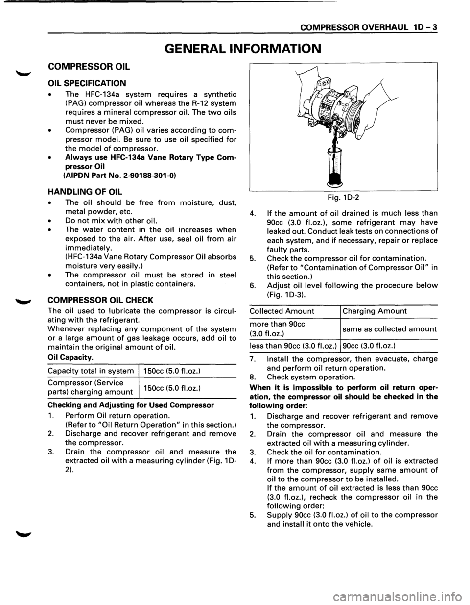
3. Drain the compressor oil and measure the
extracted oil with a measuring cylinder (Fig. 1 D-
2).
Fig. 1D-2
4. If the amount of oil drained is much less than
90cc (3.0 fl.oz.), some refrigerant may have
leaked out. Conduct leak tests on connections of
each system, and if necessary, repair or replace
faulty parts.
5. Check the compressor oil for contamination.
(Refer to "Contamination of Compressor Oil" in
this section.)
6. Adjust oil level following the procedure below
(Fig. 1 D-3).
Collected Amount
more than 90cc
(3.0 fl.oz.)
Charging Amount
same as collected amount
less than 90cc (3.0 fl.oz.) 90cc (3.0 fl.oz.)
7. Install the compressor, then evacuate, charge
and
perform oil return operation.
8. Check system operation.
When it is impossible to perform oil return oper
ation, the compressor oil should be checked in the
following order:
1. Discharge and recover refrigerant and remove
the compressor.
2. Drain the compressor oil and measure the
extracted oil with a measuring cylinder.
3. Check the oil for contamination.
4. If more than 90cc (3.0 fl.oz.) of oil is extracted
from the compressor, supply same amount of
oil to the compressor to be installed.
If
the amount of oil extracted is less than 90cc
(3.0 fl.oz.),
recheck the compressor oil in the
following order:
5. Supply 90cc (3.0 fl.oz.) of oil to the compressor
and install it onto the vehicle.