transmission ISUZU TROOPER 1995 Workshop Manual
[x] Cancel search | Manufacturer: ISUZU, Model Year: 1995, Model line: TROOPER, Model: ISUZU TROOPER 1995Pages: 1928
Page 1048 of 1928
7A-176 AUTOMATIC TRANSMISSION (4l30-E)
~-17. Fourth •
~ clutch retainer
Turbine shaft
& overrun clutch
housing assembly I
Fig. 7A-35
18
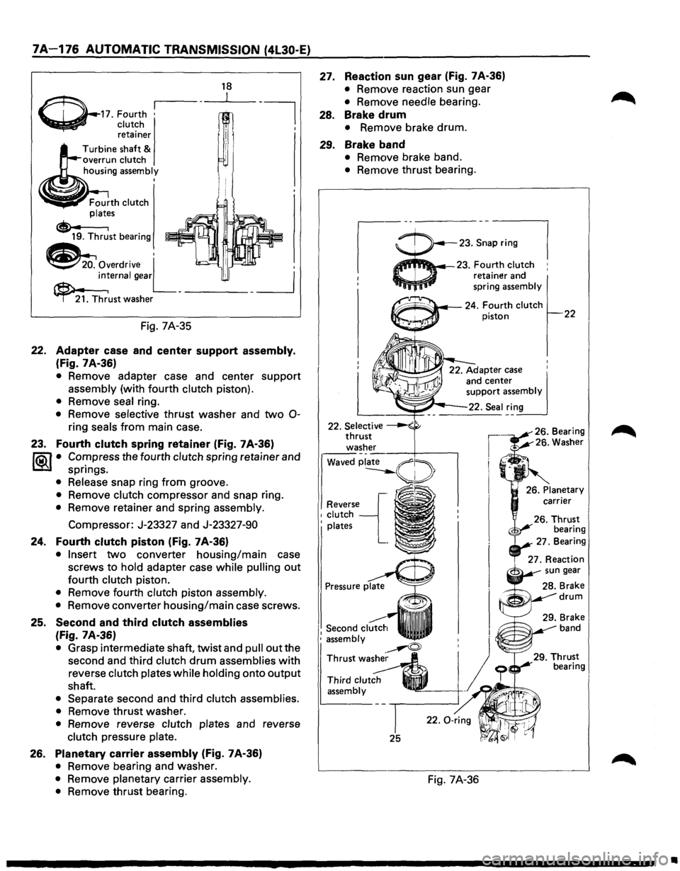
22. Adapter case and center support assembly.
(Fig. 7 A-36)
• Remove adapter case and center support
assembly (with fourth clutch piston).
• Remove seal ring.
• Remove selective thrust washer and two 0-
ring seals from main case.
23. Fourth clutch spring retainer (Fig. 7A-36)
~ • Cor:npress the fourth clutch spring retainer and
spnngs.
• Release snap ring from groove.
• Remove clutch compressor and snap ring.
• Remove retainer and spring assembly.
Compressor: J-23327 and J-23327-90
24. Fourth clutch piston (Fig. 7A-36)
• Insert two converter housing/main case
screws to
hold adapter case while pulling out
fourth clutch piston.
• Remove fourth clutch piston assembly.
•
Remove converter housing/main case screws.
25. Second and third clutch assemblies
(Fig. 7A-36)
• Grasp intermediate shaft, twist and pull out the
second and third
clutch drum assemblies with
reverse
clutch plates while holding onto output
shaft.
• Separate second and third clutch assemblies.
•
Remove thrust washer.
• Remove reverse clutch plates and reverse
clutch pressure plate.
26. Planetary carrier assembly (Fig. 7A-36)
• Remove bearing and washer.
• Remove planetary carrier assembly.
•
Remove thrust bearing.
27. Reaction sun gear (Fig. 7A-36)
• Remove reaction sun gear
• Remove needle bearing.
28. Brake drum
• Remove brake drum.
29. Brake band
• Remove brake band.
• Remove thrust bearing.
,-ii--23.~:.~
I 23. Fou_rth clutch :
1 reta~ner and
' spring
assembly
Reverse'-[. 1 clutch
' plates
~~~~ ..... -24. Fourth clutch piston 22
. 27. Re:~~~rn
Second
clutch : assembly
~
Thrustwa~~
Third clutch ._
assembly -
25
Fig. 7A-36
Brake drum
. 29. Brake
band
•
Page 1049 of 1928
30. Parking lock and selector lever assembly
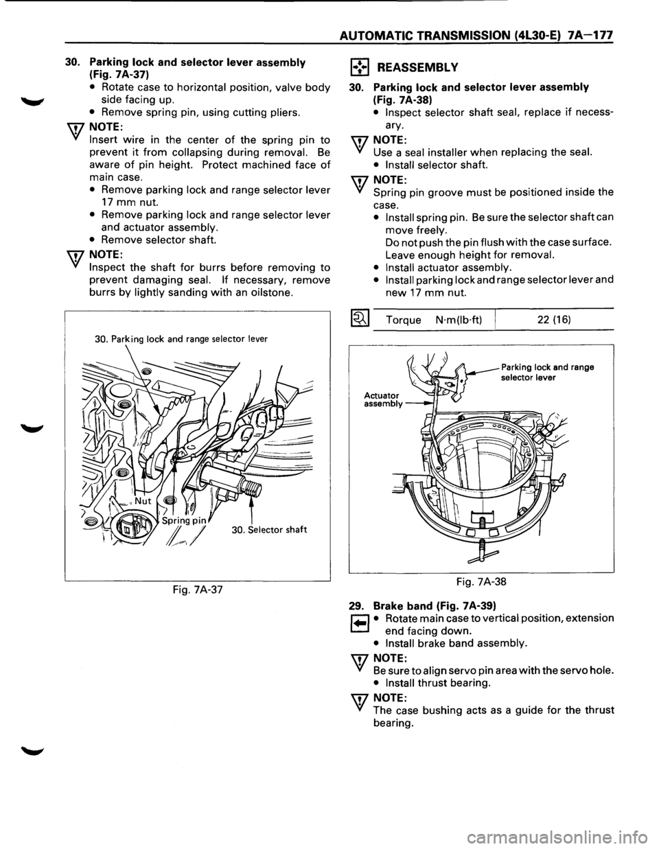
(Fig. 7A-37)
• Rotate case to horizontal position, valve body
side facing up.
• Remove spring pin, using cutting pliers.
\fl NOTE:
~ Insert wire in the center of the spring pin to
prevent it from collapsing during removal. Be
aware of pin height. Protect machined face of
main case.
• Remove parking lock and range selector lever
17 mm nut.
• Remove parking lock and range selector lever
and actuator assembly.
•
Remove selector shaft.
\fl NOTE:
~ Inspect the shaft for burrs before removing to
prevent damaging seal. If necessary, remove
burrs
by lightly sanding with an oilstone.
30. Parking lock and range selector lever
30. Selector
shaft
Fig. 7A-37
AUTOMATIC TRANSMISSION (4L30-E) 7A-177
1 .. ! .. 1 REASSEMBLY
30. Parking lock and selector lever assembly
(Fig. 7A-38)
• Inspect selector shaft seal, replace if necess
ary.
\fl NOTE:
~ Use a seal installer when replacing the seal.
• Install selector
shaft.
\fl NOTE:
~ Spring pin groove must be positioned inside the
case.
• Install spring pin. Be sure the selector shaft can
move
freely.
Do not push the pin flush with the case surface.
Leave enough
height for removal.
• Install
actuator assembly.
• Install
parking lock and range selector lever and
new 17 mm nut.
~~~ Torque N·m(lb·ft) 22 (16)
Parking lock and range selector lever
Fig. 7A-38
29. Brake band (Fig. 7A-39)
~ • Rotate main case to vertical position, extension
~ end facing down.
• Install brake band assembly.
\fl NOTE:
~ Be sure to align servo pin area with the servo hole.
• Install
thrust bearing.
\fl NOTE:
~ The case bushing acts as a guide for the thrust
bearing.
Page 1050 of 1928
7A-178 AUTOMATIC TRANSMISSION (4L30-E)
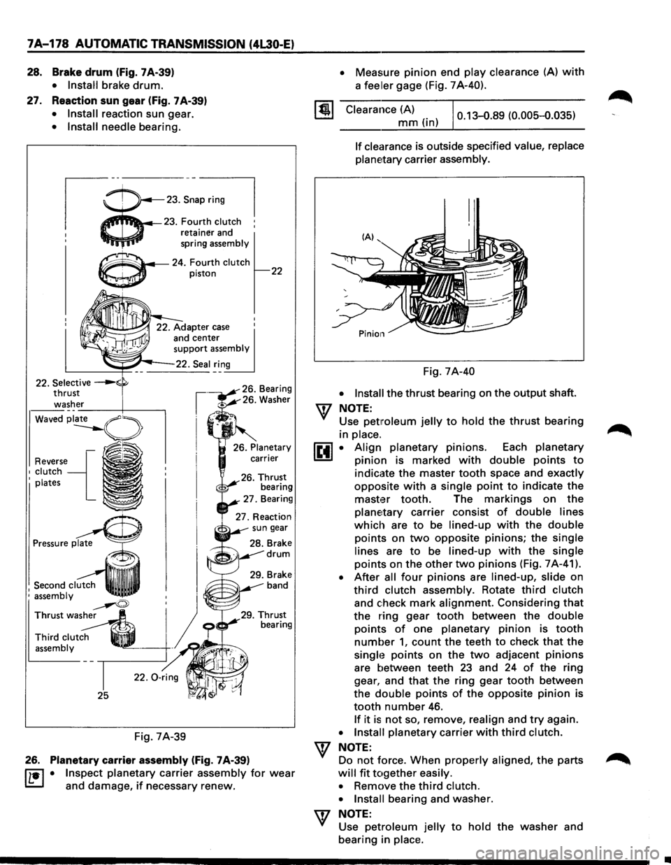
28. Brake drum (fig. 7 A-39)
27.
• Install brake drum.
Reaction sun gear (Fig. 7A-39)
• Install reaction sun gear.
• Install needle bearing.
23.S~a=l
4'i'fl._.l4--23. Fourth clutch :
retainer and
spring
assembly
~~..,...~---24. Fourth clutch
Waved
Reverse{ 1 clutch I plates
1 Second clutch ' assembly
~ Thrust wash~
Third clut~ q_ assembly .
25
Fig. 7A-39
piston
26. Planetary carrier assembly (Fig. 7 A-39)
22
IL•I • Inspect planetary carrier assembly for wear
and damage, if necessary renew.
• Measure pinion end play clearance (A) with
a feeler gage (Fig. 7A-40).
Clearance (A)
mm (in) 0.13-0.89 (0.005-0.035)
If clearance
is outside specified value, replace
planetary
carrier assembly.
Fig. 7A-40
• Install the thrust bearing on the output shaft.
\f NOTE:
Use petmleum jelly to hold the thrust bearing
in
place.
~·
•
Align planetary pinions. Each planetary
pinion is marked with double points to
indicate the master tooth space and exactly
opposite with a single point to indicate the
master tooth. The markings on the
planetary carrier consist of double lines
which are to be lined-up with the double
points on two opposite pinions; the single
lines
are to be lined-up with the single
points on the other two pinions (Fig. 7 A-41 ).
After all four pinions are lined-up, slide on
third clutch assembly. Rotate third clutch
and check mark alignment. Considering that
the ring gear tooth between the double
points of one planetary pinion is tooth
number 1, count the teeth to check that the
singh~ points on the two adjacent pinions
are between teeth 23 and 24 of the ring
gear, and
that the ring gear tooth between
the
double points of the opposite pinion is
tooth number 46.
If it is not so, remove, realign and try again.
• Install planetary carrier with third clutch.
\f NOTE:
Do not force. When properly aligned, the parts
will fit together easily.
•
Remove the third clutch.
• Install
bearing and washer.
\f NOTE:
Use petroleum jelly to hold the washer and
bearing in
place.
•
Page 1051 of 1928
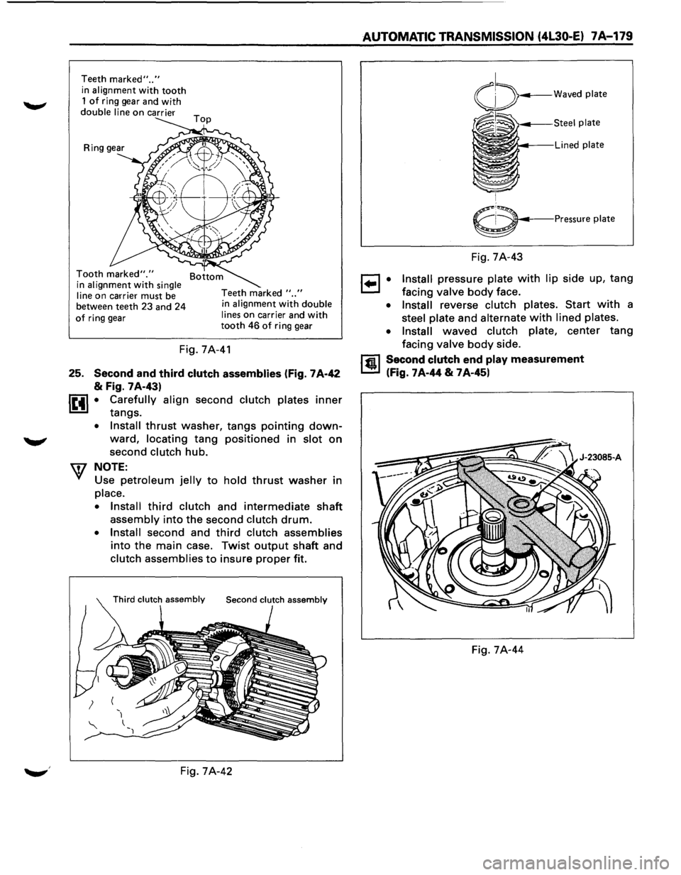
Teeth marked" .. "
in alignment with tooth 1 of ring gear and with
double line on carrier
Tooth marked"." in alignment with single
line
on carrier must be
between teeth 23 and 24
of ring gear Teeth
marked
" .. " in alignment with double
lines
on carrier and with tooth 46 of ring gear
Fig. 7A-41
25. Second and third clutch assemblies (Fig. 7 A-42
& Fig. 7A-43)
lttl • Carefully align second clutch plates inner
tangs.
• Install thrust washer, tangs pointing down
ward, locating tang positioned in slot on
second clutch hub.
W NOTE:
Use petroleum jelly to hold thrust washer in
place.
• Install
third clutch and intermediate shaft
assembly into the second clutch drum.
• Install second and third clutch assemblies
into the main case. Twist output shaft and
clutch assemblies to insure proper fit.
Fig. 7A-42
AUTOMATIC TRANSMISSION (4L30·E) 7A-179
6---Pressure plate
Fig. 7A-43
1 .. 1 • Install pressure plate with lip side up, tang
facing valve body face.
• Install reverse clutch plates. Start with a
steel plate and alternate with lined plates.
• Install
waved clutch plate, center tang
facing
valve body side.
rfil Second clutch end play measurement
L.!!!l (Fig. 7A-44 & 7A-45l
Fig. 7A-44
Page 1052 of 1928
7A-180 AUTOMATIC TRANSMISSION (4L30-E)
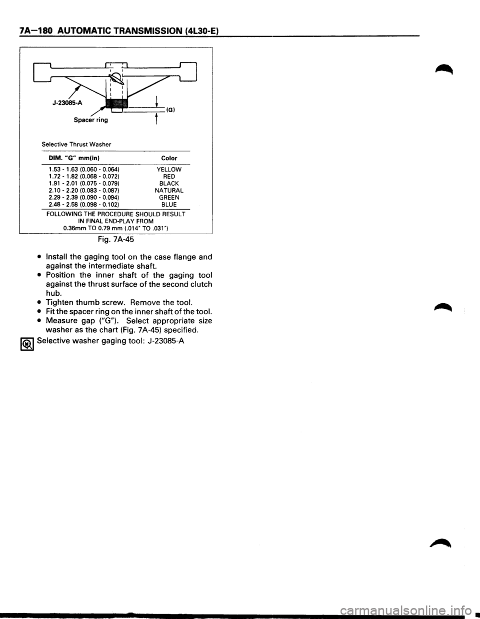
Selective Thrust Washer
DIM. "G" mm(in)
1.53 -1.63 (0.060 -0.064} 1. 72 -1.82 (0.068 -0.072} 1.91 -2.01 (0.075 -0.079}
2.10 -2.20 (0.083 -0.087} 2.29 -2.39 (0.090 -0.094} 2.48 -2.58 (0.098 -0.1 02)
Color
YELLOW RED BLACK NATURAL GREEN BLUE
FOLLOWING THE PROCEDURE SHOULD RESULT IN FINAL END-PLAY FROM 0.36mm TO 0.79 mm (.014" TO .031")
Fig. 7A-45
• Install the gaging tool on the case flange and
against the intermediate shaft.
• Position the inner shaft of the gaging tool
against the thrust surface of the second clutch
hub.
• Tighten thumb screw. Remove the tool.
•
Fit the spacer ring on the inner shaft of the tool.
•
Measure gap ("G"). Select appropriate size
washer as the chart (Fig. 7A-45) specified.
1<&1 Selective washer gaging tool: J-23085-A
•
Page 1053 of 1928
AUTOMATIC TRANSMISSION (4L30-E) 7A-181
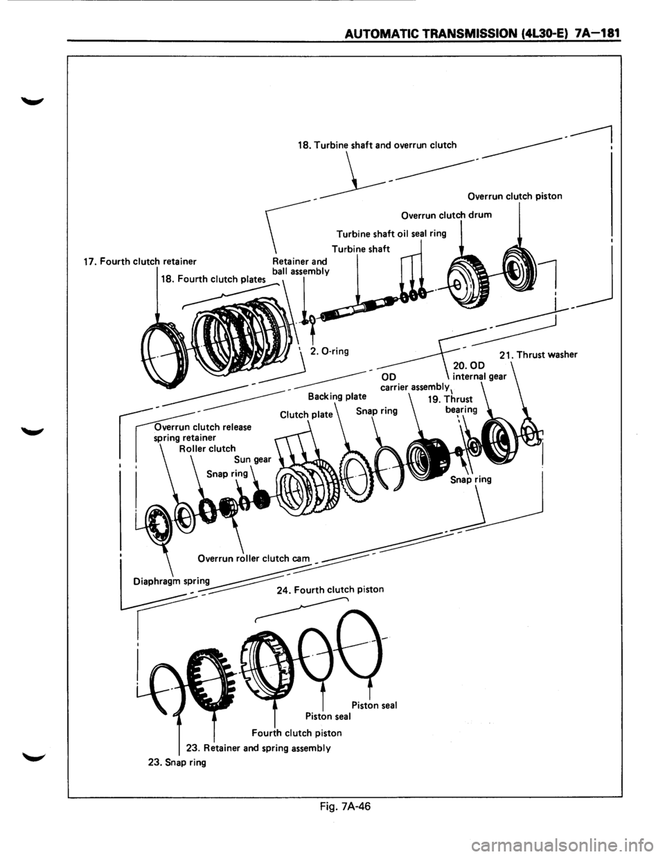
------1 18. Turbine shaft and overrun clutch ---------------1
_ __1------------:~"""clutch p;ston
Overrun clutch drum
Turbine shaft oil seal ring
Turbine shaft
21. Thrust washer
00 internal gear carrier assembly 1 19. Thrust
be~ ring
'
_]'
' o'"''""'.""elutc~~
Diaphragm spring ~
r~~hp; .. on
I
I '
Fourth clutch piston
23. Retainer
and spring assembly
23.
Snap ring
Fig. 7A-46
Page 1054 of 1928
7A-182 AUTOMATIC TRANSMISSION (4l30-E)
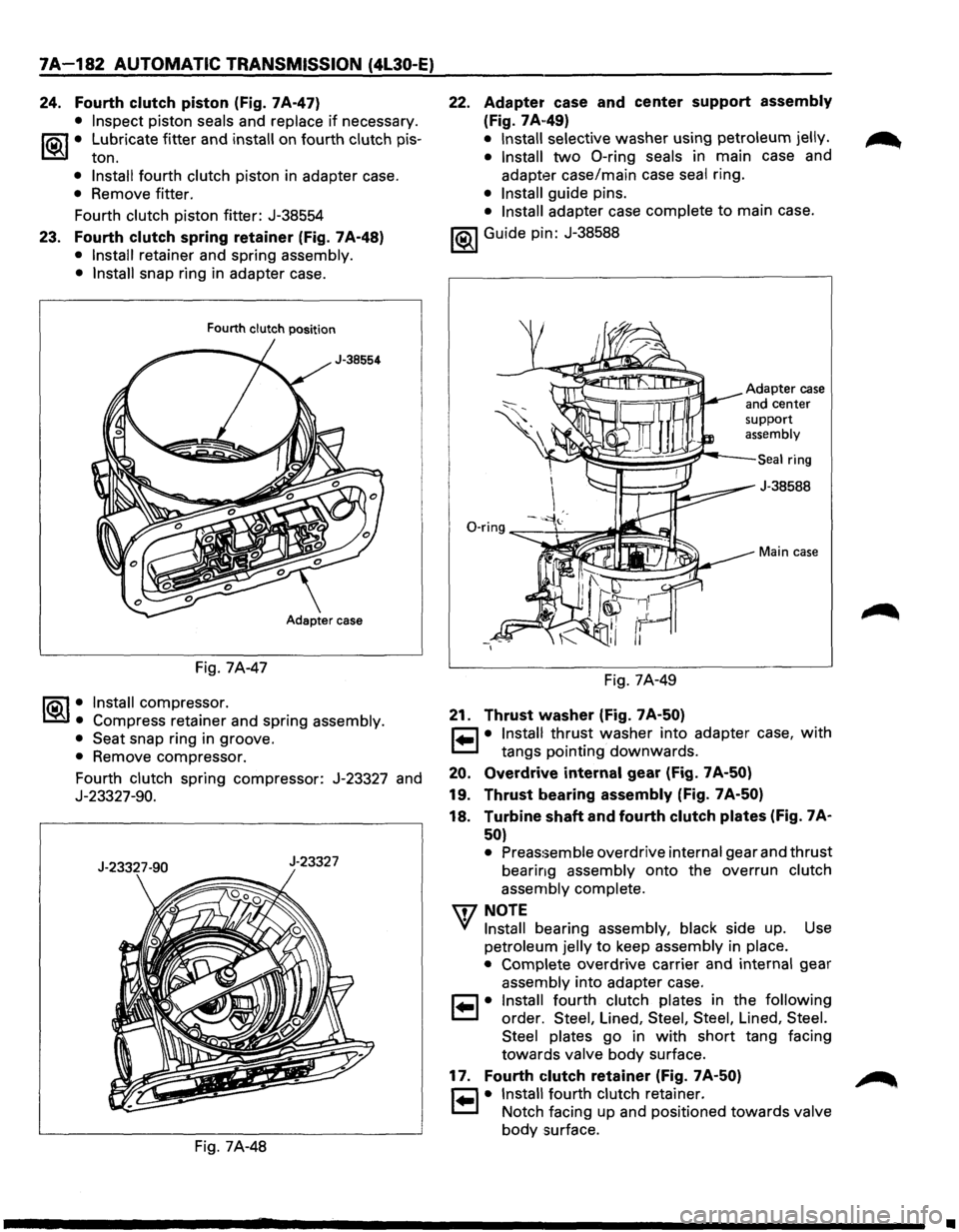
24. Fourth clutch piston (Fig. 7A-47)
• Inspect piston seals and replace if necessary.
1®-f• Lubricate fitter and install on fourth clutch pis-
ton.
• Install fourth clutch piston in adapter case.
• Remove fitter.
Fourth
clutch piston fitter: J-38554
23. Fourth clutch spring retainer (Fig. 7A-48)
• Install retainer and spring assembly.
• Install snap ring in adapter case.
Fourth clutch position
Fig. 7A-47
1®-1•. Install compressor.
Compress retainer and spring assembly.
• Seat snap ring in groove.
• Remove compressor.
Fourth
clutch spring compressor: J-23327 and
J-23327-90.
J-23327-90 J-23327
Fig. 7A-48
22.
Adapter case and center support assembly
(Fig. 7A .. 49)
• Install selective washer using petroleum jelly.
• Install
two 0-ring seals in main case and
adapter case/main case seal ring.
• Install guide pins.
• Install adapter case complete to main case.
1®1 Guide pin: J-38588
Adapter case
and center support assembly
~~§~~~r---Seal ring
-,
Fig. 7A-49
21. Thrust washer (Fig. 7 A-50)
J-38588
Main case
c::J • Install thrust washer into adapter case, with
~ tangs pointing downwards.
20. Overdrive internal gear (Fig. 7A-50)
19. Thrust bearing assembly (Fig. 7A-50)
18. Turbine shaft and fourth clutch plates (Fig. 7A·
50)
• Preassemble overdrive internal gear and thrust
bearing assembly onto the overrun clutch
assembly complete.
\f!NOTE
Yl Install bearing assembly, black side up. Use
petroleum
jelly to keep assembly in place.
• Complete overdrive carrier and internal gear
assembly into adapter case.
1•1• Install fourth clutch plates in the following
order. Steel, Lined, Steel, Steel, Lined, Steel.
Steel plates
go in with short tang facing
towards valve body surface.
17. Fourth clutch retainer (Fig. 7A-50) ~
1•1• Install fourth clutch retainer.
Notch facing up and positioned towards valve
body surface.
•
Page 1055 of 1928
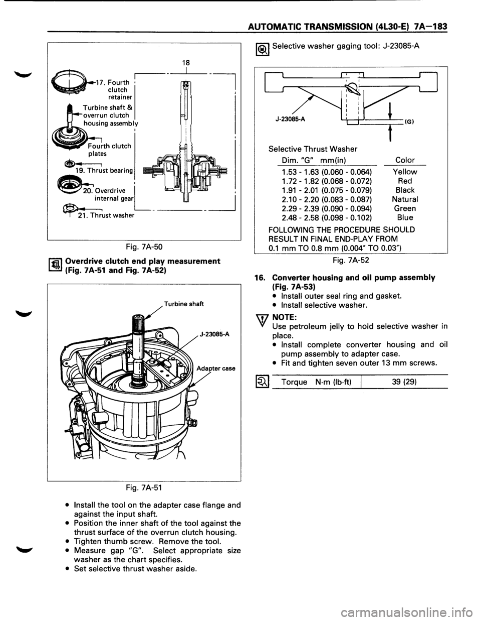
~~11. Fourth •
~ clutch
___,,.,.,.,.
retainer
Turbine shaft
& overrun clutch
housing assembly
Fourth clutch
plates
®• I 19. Thrust bearing
18
~Overdrive L' ,
~ernal gear _ ------_j
~ 2l. Thr~st washer
Fig. 7A-50
rfi:il Overdrive clutch end play measurement
~ (Fig. 7A-51 and Fig. 7A-52)
Turbine shaft
J-23085-A
case
Fig. 7A-51
• Install the tool on the adapter case flange and
against the
input shaft.
• Position the inner shaft of the tool against the
thrust surface
of the overrun clutch housing.
• Tighten thumb screw. Remove the tool.
• Measure gap "G". Select appropriate size
washer
as the chart specifies.
• Set selective thrust washer aside.
AUTOMATIC TRANSMISSION (4L30-E) 7A-183
1®.1 Selective washer gaging tool: J-23085-A
J-23085-A
Selective Thrust Washer
Dim.
"G" mm(in) Color
1.53-1.63 (0.060- 0.064) Yellow
1. 72 - 1 .82 (0.068 -0.072) Red
1.91 -2.01 (0.075 -0.079) Black
2.10-2.20 (0.083-0.087) Natural
2.29 -2.39
(0.090 -0.094) Green
2.48 -2.58
(0.098 -0.1 02) Blue
FOLLOWING THE PROCEDURE SHOULD
RESULT
IN FINAL END-PLAY FROM
0.1 mm TO 0.8 mm (0.004" TO 0.03")
Fig. 7A-52
16.
Converter housing and oil pump assembly
(Fig. 7A-53)
• Install outer seal ring and gasket.
• Install selective washer.
W NOTE:
VI Use petroleum jelly to hold selective washer in
place.
• Install
complete converter housing and oil
pump
assembly to adapter case.
• Fit and tighten seven outer 13 mm screws.
~~~ Torque N·m (lb·ft) j 39 (29)
Page 1056 of 1928
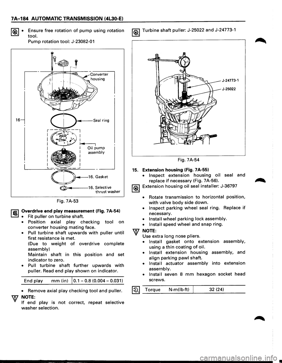
7A-184 AUTOMATIC TRANSMISSION (4L30-E)
~· Ensure free rotation of pump using rotation
tool.
16
Pump rotation tool: J-23082-01
-----16. Selective thrust washer
Fig. 7A-53
l'fil Overdrive end play measurement (Fig. 7A-54)
~ • Fit puller on turbine shaft.
• Position axial play checking tool on
converter housing mating face.
• Pull turbine shaft upwards with puller until
first resistance is met.
(Due
to weight of overdrive complete
assembly)
Maintain shaft in this position and set
indicator to zero.
• Pull turbine shaft further upwards with
puller. Read end play shown on indicator.
End
play mm (in) I 0.1 -0.8 (0.004-0.031)
1®.1 Turbine shaft puller: J-25022 and J-24773-1
J-24773·1
J-25022
Fig. 7A-54
15. Extension housing (Fig. 7A-55)
• Inspect extension housing oil seal and
replace if necessary (Fig. 7 A-56).
1®.1 Extension housing oil seal installer: J-36797
• Rotate transmission to horizontal position,
with valve body side down.
• Inspect parking wheel seal ring. Replace if
necessary.
• Install wheel parking lock assembly.
• Install
speed wheel and snap ring.
NOTE:
Use extra long nose pliers.
• Install
gasket onto extension assembly,
usin£1 a thin coating of oil.
• Install
extension housing assembly, and
align parking pawl shaft.
• Install actuator assembly into extension
assembly.
• Install
seven 8 mm hexagon socket head
screws.
• Remove axial play checking tool and puller. ~~~ Torque N-m(lb.ft) 32 (24) W NOTE: _ __:_ ___ __:___:__J_ _ __.::..:::....=_:..:.__ __
If end play is not correct, repeat selective
washer selection.
Page 1057 of 1928
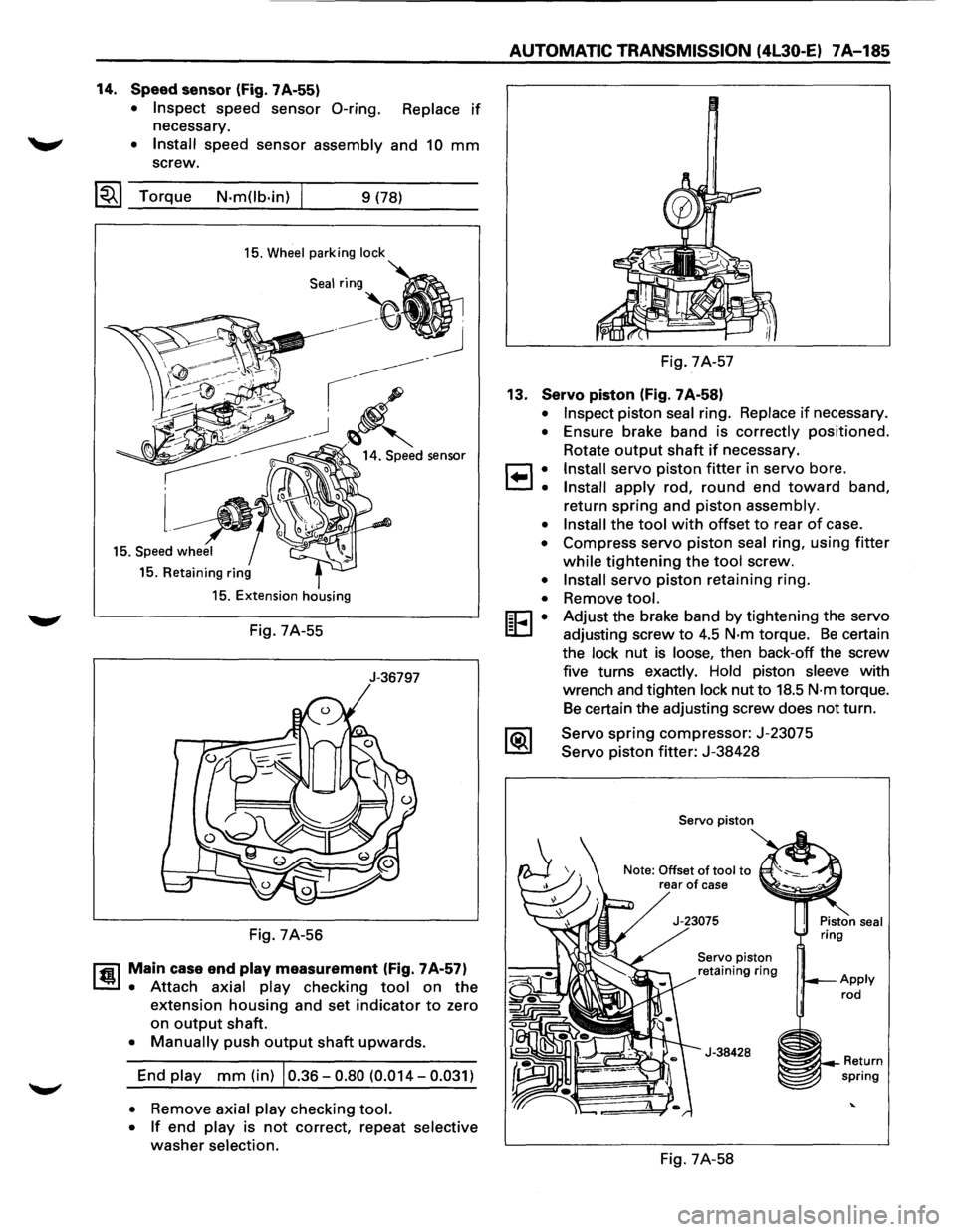
14. Speed sensor (Fig. 7A-55)
• Inspect speed sensor 0-ring. Replace if
necessary.
~ • Install speed sensor assembly and 10 mm
screw.
~~~ Torque N-m(lb-in) 9 (78)
15. Wheel parking lock
15. Retaining ring
15. Extension housing
Fig. 7A-55
J-36797
Fig. 7A-56
rfil Main case end play measurement (Fig. 7A-57)
~ • Attach axial play checking tool on the
extension housing and set indicator to zero
on
output shaft.
• Manually push output shaft upwards.
End play mm (in) 10.36-0.80 (0.014-0.031)
• Remove axial play checking tool.
• If end play is not correct, repeat selective
washer selection.
AUTOMATIC TRANSMISSION (4l30-E) 7A-185
Fig. 7A-57
13. Servo piston (Fig. 7A-58)
•
•
8:
•
•
•
•
[E•
Inspect piston seal ring. Replace if necessary .
Ensure brake band is correctly
positioned .
Rotate
output shaft if necessary.
Install servo piston fitter in servo bore.
Install apply rod, round end toward band,
return
spring and piston assembly.
Install the tool with offset to rear of case .
Compress servo
piston seal ring, using fitter
while tightening the tool screw.
Install servo piston retaining ring .
Remove
tool.
Adjust the brake band by tightening the servo
adjusting screw
to 4.5 N-m torque. Be certain
the lock nut
is loose, then back-off the screw
five turns exactly. Hold piston sleeve with
wrench and tighten lock nut to
18.5 N-m torque.
Be certain the adjusting screw does not turn.
Servo
spring compressor: J-23075
Servo piston fitter: J-38428
Servo piston
Note: Offset
of tool to rear of case
Servo piston
retaining ring
J-38428
Fig. 7A-58
~~--Return spring