transmission ISUZU TROOPER 1995 Workshop Manual
[x] Cancel search | Manufacturer: ISUZU, Model Year: 1995, Model line: TROOPER, Model: ISUZU TROOPER 1995Pages: 1928
Page 1018 of 1928
7A-146 AUTOMATIC TRANSMISSION (4L30-E)
INTERMITTENT CONDITIONS
If the TECH1 displays a diagnostic trouble code as
intermittent, or if after a test drive a DTC does not
reappear though the detection conditions for this
DTC are present: the problem is most likely a faulty
electrical connection or loose wiring. Terminals
and
grounds should always be the prime suspect.
lntermittents rarely occur inside sophisticated
electronic components such
as the TCM.
Use the
DTC information to understand which wires
and sensors are involved.
When an
intermittent problem is encountered,
check suspect circuits for:
(1) Poor terminal to wire connection.
(2) Terminals not fully seated in the connector
body (backed out).
(3) Improperly formed or damaged terminals.
(4) Loose, dirty, or corroded ground connections:
HINT: Any time you have an intermittent in
more than one circuit, check whether the circuits
share a
common ground connection.
(5) Pinched or damaged wires.
(6) Electro-Magnetic Interference (EMI):
HINT:
Check that all wires are properly routed
away from spark plug wires, distributor wires,
coil, and generator. Also check
for improperly
installed electrical options, such as lights, 2-way
radios, etc. Use
the
F3: SNAPSHOT mode of the TECH 1 to help
isolate the cause
of an intermittent fault. The
snapshot
mode will record information before and
after the problem occurs. Set the snapshot
to
"trigger" on the suspect DTC or, if you notice the
reported
symptom during test drive, trigger the
snapshot
manually.
(1) NOTE: When TECH1 is plugged the shifts are
always
done at the maximum pressure. This
means
that if you do SNAPSHOT while driving
you will! notice firm shifts.
After the snapshot has been triggered, command
the TECH1 to play back the flow of data recorded
from each of the various sensors. Signs of an
intermittent fault in a sensor circuit are sudden
unexplainable jump in data values out of the
normal range.
CASE:
problem still not solved GOTO TCM MEM
CAL REPLACEMENT.
•
Page 1019 of 1928
AUTOMATIC TRANSMISSION (4L30-E) 7A-147
TCM MEM-CAL REPLACEMENT
(TCM: Transmission Control Module)
1. MEM-CAL (Memory and Calibration Unit)
Information for specific transmission and vehicle is
programmed using an integrated circuit called a
MEM-CAL.
This allows one model of controller to be used for
many different vehicles.
The MEM-CAL is located inside the TCM and has
information on the transmission, shift map, etc.
several others.
2. MEM-CAL Replacement
If the diagnostic procedures require MEM-CAL
replacement,
the MEM-CAL should be replaced
using the following procedures.
NOTICE:
The ignition must be "OFF", when disconnecting or
reconnecting the TCM connector, to prevent
internal damage to the TCM.
NOTICE:
To prevent possible Electrostatic Discharge damage
to the TCM, do not touch the connector pins or
soldered components on the circuit board.
MEM-CAL Replacement Procedure:
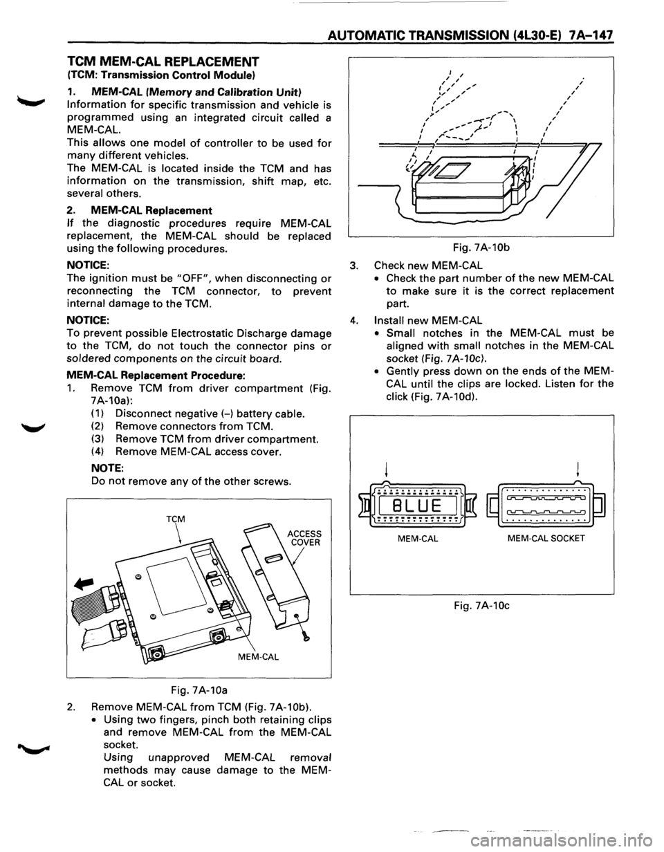
1. Remove TCM from driver compartment (Fig.
7A-10a):
( 1) Disconnect negative (-) battery cable.
(2) Remove connectors from TCM.
(3) Remove TCM from driver compartment.
(4) Remove MEM-CAL access cover.
NOTE:
Do not remove any of the other screws.
Fig.
7A-10a
2. Remove MEM-CAL from TCM (Fig. 7A-10b).
•
Using two fingers, pinch both retaining clips
and remove MEM-CAL from the MEM-CAL
socket.
Using unapproved
methods may cause
CAL or socket.
MEM-CAL removal
damage to the MEM- Fig.
7A-10b
3. Check new MEM-CAL
• Check
the part number of the new MEM-CAL
to make sure it is the correct replacement
part.
4. Install new MEM-CAL
• Small notches in the MEM-CAL must be
aligned with small notches in the MEM-CAL
socket (Fig.
7A-10c).
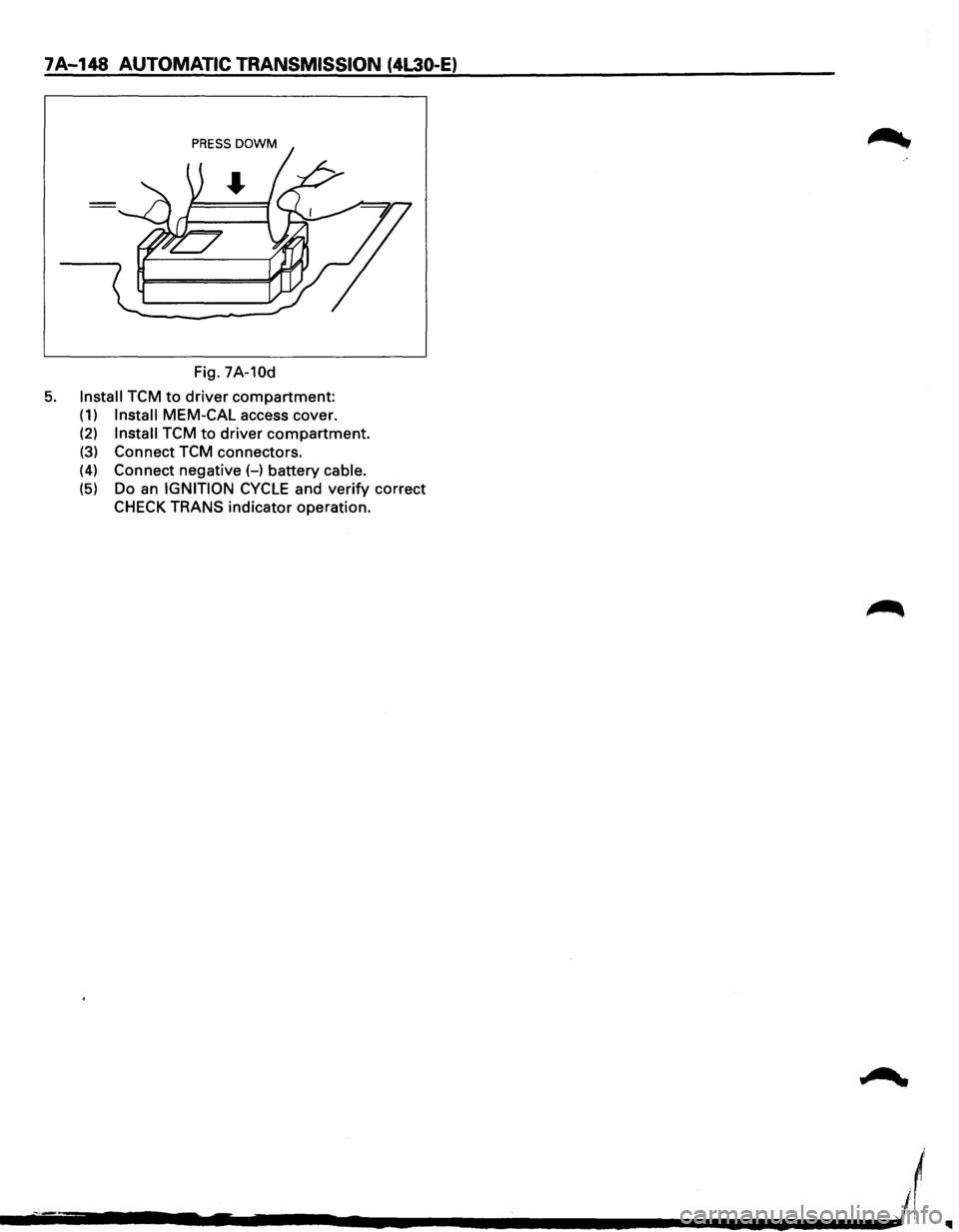
• Gently
press down on the ends of the MEM
CAL
until the clips are locked. Listen for the
click (Fig. 7A-10d).
! !
($I~rn~ ~~~) . . . . . . . . . . . . . . . ............ .
MEM-CAL MEM-CAL SOCKET
Fig. 7A-10c
Page 1020 of 1928
7A-148 AUTOMATIC TRANSMISSION (4L30-E)
Fig. 7A-10d
5. Install TCM to driver compartment:
(1) Install MEM-CAL access cover.
(2) Install TCM to driver compartment.
(3) Connect TCM connectors.
(4) Connect negative(-) battery cable.
(5) Do an IGNITION CYCLE and verify correct
CHECK TRANS indicator operation.
l
--------~.-------~------------~~--~'1
Page 1021 of 1928
 7A-149
MEMO
... . \"-
--·-----·--·-········-.. ·····-·····----------·-····\
·-······-········----------\
----------------·Â")
AUTOMATIC TRANSMISSION (4L30-E) 7A-149
MEMO
... . "-'
--·-----·--·-········-.. ·····-·····----------·-····\
·-······-········----------\
----------------····--------····.··-------\
--------············-··--··\
···············-···\
·------
Page 1022 of 1928
7A-150 AUTOMATIC TRANSMISSION (4L30-E)
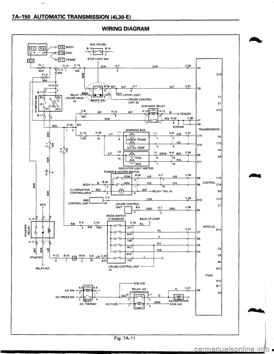
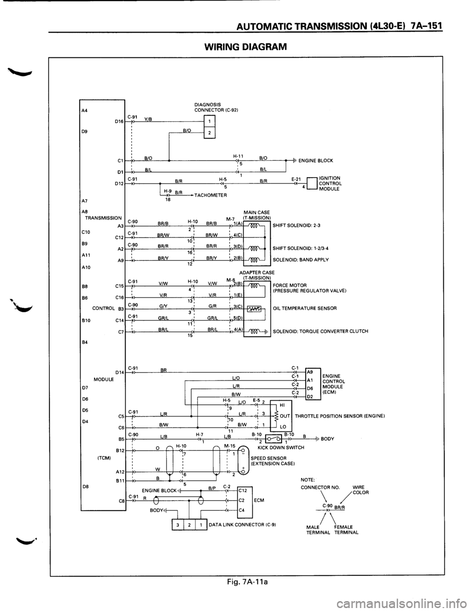
WIRING DIAGRAM
L--<~o-~~~~~~--~~~----~~~----~~--------------~G"IW~------------C«-9_0--iA4
D16
30A
D12
GfY ---~:at--B-'li BfY G(Y H-7 ,...-..~., 4,' ~ ~
RELAY ~' ~:iO 1 [my_ STOP LIGHT
2 3 I CRUISE MAIN '..BRAKES '' L------•CRUISE CONTROL (4) - ---vy UNIT (8) D1
~2
8-11+~---f4
~ 81~ Q._ ("'~2
~ IG1 18~ ~ ST ACC en 8-11
C-91 D9
C1
ECM MAIN RELAY
X-f~ ~X~~2 8 II• FENDER R/W : - : RiG H-42 C-90 '-----t--t------+-------!:!Lll----------< • ~( r fl A7 2 4 8 L....{+--AS
C-8
~A
H-13 BfY BfY 3 7 3
L-+-JB~~I,_IG __ __....,~4-B(Y ECM(A61 1 3 WARNING BOX TRANSMISSION
~T'~5'-'1:D----H-+~2~5 LfY ~~~ ~K TRANS 1-,17 Hr7 :~ C-~1 C10 C::
0 ~
"' <( u :!?
'----~
"' ":' 0'> J:
IXl ~ a: ~
I~ A10 AJT OIL TEMP 2
8
A
2
LfY 1-9~ ~1-9 GR/W H;9 BiG C-90 89 1~ POW. : 8 ~3 , A9
- -~· PiG c(-A11 WIN. 7 19 INDICATOR LIGHT (METER) POWER & WINTER SWITCH
_,. POW. 8-30 ViR H-,>,7:;-----'V"-'iR.!..,_ ___ c<-~9-0-l B8 C15 II-v 3, :7 • BODY of~~ ~-o-WIN. 1 ,' ViG -----.+.,.,176 __ ____;;V.:..;iG=-----<+'-----1 B
6 CONTROL C16 ,4 ILLUMINATION~' ~ '~RELAY: TAIL (4) CONTROLLER(3) 2 -~ 5
ABS ~c~4----------------__yV:J..:!:!._/W ______________ ___:C<-~9:..::0-l B 10 CONTROL UNIT 16 CRUISE CONTROL
RiB H-8 C-43
4 RiB 5(D)
UNIT Q;·>-9------"G,_,Ri_,L_~:+--;-----'G""R""iL::,_ ___ c,-+-9-0----j 84
MODE SWITCH
IT-MISSION)
C-43
2(F) ~ ' 8(A), '
BACKUP LAMP
RiL
t
PiL
p
C-91 ( D7 : D6
B3
C14
C7
MODULE D14
: D5 : C5 ( D4 C6
B5
7(B)'
X-17-l-~J,-~L -v-: 6((:1§': :
r! -v-u-3tGi'', STARTER H-~..._:4---4r::J-Mo~-_B~;~;8 LJR C;~434--o-_,_-o---+---<·' L ---1 8 1 [::::J 2 15 4(H) u---~< 1 '
CRUISE CONTROL UNIT RELAY;A/C (4)
DB
(TCM) 812
A12
811
C8
....
'
Fig.7A·11 I
------------------------~~
•
Page 1023 of 1928
A4
D16
D9
C1
D1
D12
A7
AB
TRANSMISSION
A3 C10 C12
B9
A2
All A9 A10
BB C15
B6 C16
CONTROL
B3
B10 C14
C7
B4
D14
MODULE
D7 D6
D5
C5 D4 C6
B5
B12
(TCMI
A12 B11
DB
CB
AUTOMATIC TRANSMISSION (4l30-E) 7 A-151
WIRING DIAGRAM
DIAGNOSIS
CONNECTOR (C-921 C-91
1: : j
B/0 B
I
I B/L
C-91 BIR :
G9 BIR 18
C-90 BRIB )
C-91 ) BR!W
C-90
BRIR I
I BR/Y )
C-91 V/W
'
' VIR )
C-90 G/Y
C-91 GRIL ) '
' BRIL :
C-91 BR
C-91 UR
: B/W
C-90 LIB )
;&"
r-r ,7 ' '
' '
' '
rt' w ,6
' B '
1---+: 5
ENGINE BLOCK •I C-91 R v
BODY•I~
H-11 B/0
'::5 B/L
1
H-5 BIR
(( 5
J
II• ENGINE B LOCK
E-~1 GNITION
ONTROL
MODULE ( 4 c
TACHOMETER
H-10
BRIB 'I 2 I
,J BR!W
I BRIR 16, ' BR/Y (( 12
H-10
4 ~ VC:!:f._
,j VIR
' GIR 3, ' GRIL ,,'~ ' BRIL (( 15
H-7 ((1
---
'r
B/P
1
v
I
MAIN CASE M-71(1 IT-MISSION) /1 A -'m'-SHIFT SOLENOID: 2-3 I I 4(C
: 3(0 -'m'-SHIFT SOLENOID: 1-2 /3-4
:, 21B -'100"'--SOLENOID: BAND AP PLY
ADAPTER
CASE
M-6211 IT-MISSION) FORCE MOTOR I 2 B
~ : liE (PRESSURE REGULAT OR VALVE)
I : 31C rAAUr1 '-== : SID I :, 41A ~I•
uo
UR
B/W
H-5
E 1-5 2 ~9 LIO
'
OIL TEMPERATURES
SOLENOID:
TORQUE
C-1 ..---A9 C-1 A1 C-2 D6 C-2
.-----.£L HI .?
ENSOR
CONVERTER CLUTCH
ENGINE CONTROL
MODULE (ECMI
\,o LIR < 3 OUT THROTTLE P OSITION SENSOR (ENGINE) ; B/W
' 1 LO 11 B-~10 LIB B ( 2 1 ~) II• BODY
"] "" oow' ""''" 1 -
: SPEED SENSOR : (EXTENSION CASE I ' + 2 NOTE:
't]
CONNEC
C12
: C2 ECM
C4 TOR
NO. WIRE /COLOR
~90 BRIR
I 3 I 2 I 1 I DATA LINK CONNECTOR (C-91 / MALE FEMALE TERMINAL TERMINAL
Fig.
7A-11a
Page 1024 of 1928
•
, cCi" -.J )> I .... N
RELAY
& FUSE BOX
(FL-1, FL-2, FL-3)
THROTTLE BODYASM SPEED SENSOR
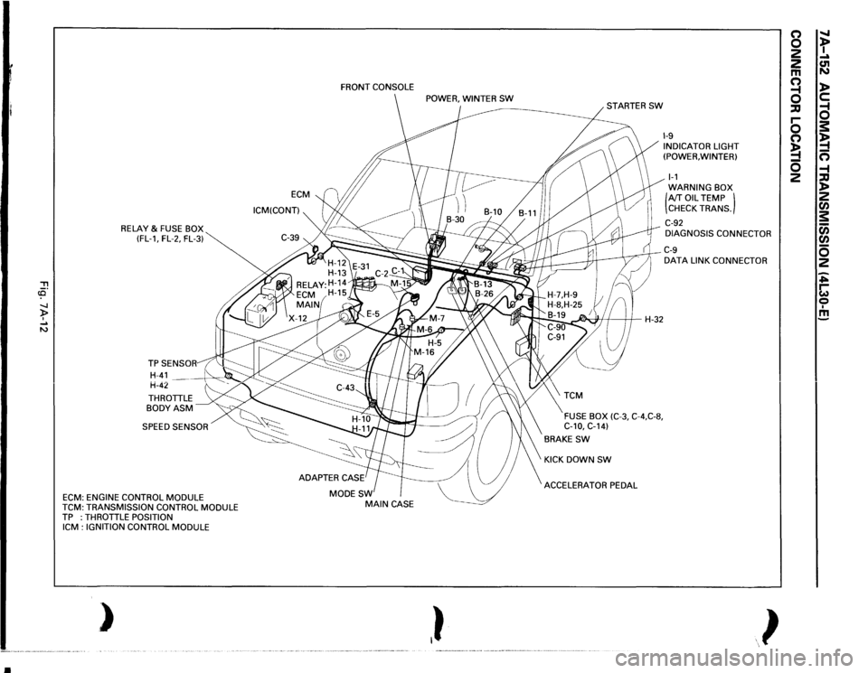
ECM:
ENGINE CONTROL
MODULE
TCM:
TRANSMISSION CONTROL
MODULE
TP :THROTTLE
POSITION
ICM
: IGNITION CONTROL
MODULE
)
ECM
ICM(CONT) FRONT
CONSOLE
MODESW
MAIN
CASE
,}
~H-32
FUSE BOX
(C-3,
C-4,C-8,
C-10,
C-14)
BRAKE
SW
KICK DOWN
SW
ACCELERATOR PEDAL
1-9 INDICATOR LIGHT
(POWER, WINTER) 1-1 WARNING BOX (AfT
OIL
TEMP )
CHECK TRANS.
C-92 DIAGNOSIS CONNECTOR C-9 DATA
LINK CONNECTOR
}
(') 0 2
2 m a ::IJ r-0 (') !4 0 2
" t .... C1l N l> c: a s: !4 n -4 ::IJ l> 2 rA s: c;; rA 0 2 ~ ~ 0 I m
Page 1025 of 1928
AUTOMATIC TRANSMISSION (4L30-E) 7A-153
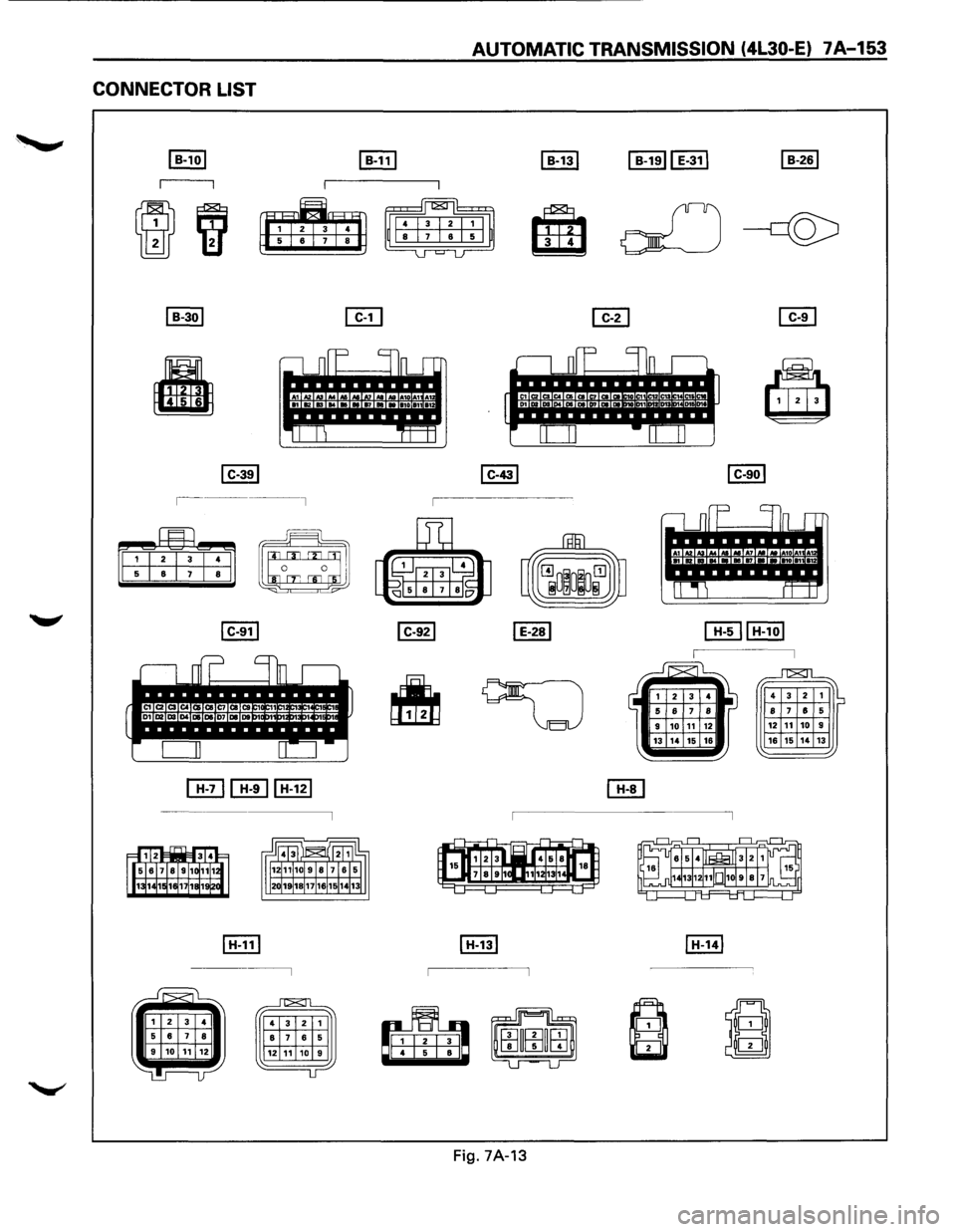
CONNECTOR LIST
~
~
~ I
p
, .. ....
c
lrL ---,
.. 1 A1 A1 • , 12 ..... ... I 011 11
Tl '"!
I H-111 I H-131
-------,
fflb
Fig. 7A-13
~ I
:::::J _jn ,..,
., .. .. M A7
~~ i ., .. .... ....
'"!
~
4 3 2 1 ~ 8 7 8 5 12 11 10 9
16 15 14 13
I H-141
Q m
Page 1026 of 1928
7A-154 AUTOMATIC TRANSMISSION (4l30-E)
a
~-·
CITHEJ lx-12l I X-171
Eili3 4
•
3
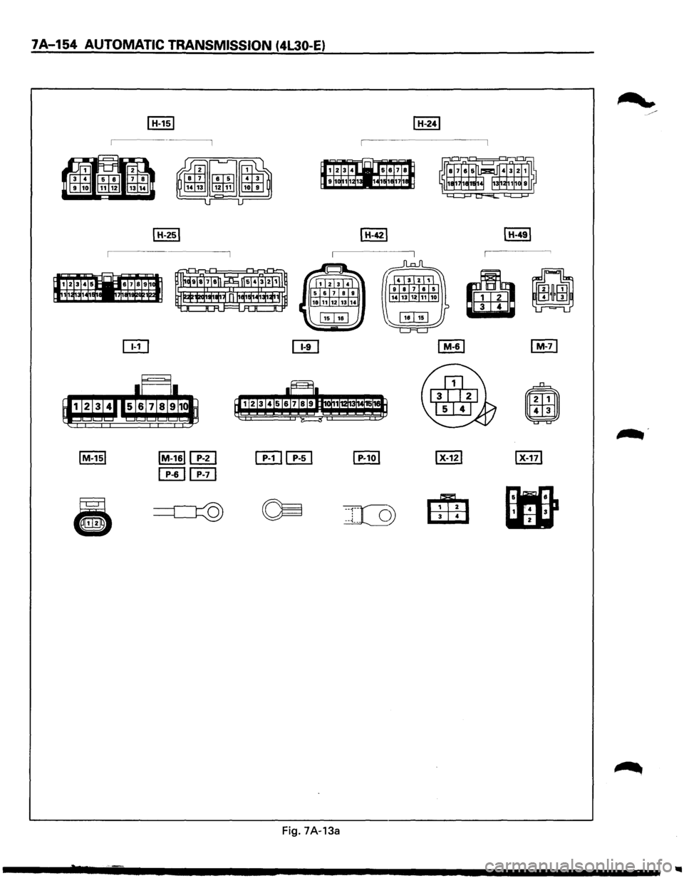
Fig. 7A-13a
Page 1027 of 1928
... ......,.
AUTOMATIC TRANSMISSION (4L30-E) 7A-155
ON-VEHICLE SERVICE
CHECKING TRANSMISSION FLUID
LEVEL
1. Park the vehicle on level ground.
2. Apply the parking brake.
3. Place the automatic transmission in "Park" and
start the engine.
Allow the engine to idle for
two minutes.
4. With the brakes applied, move the shifter lever
through all the gear ranges, ending in "Park".
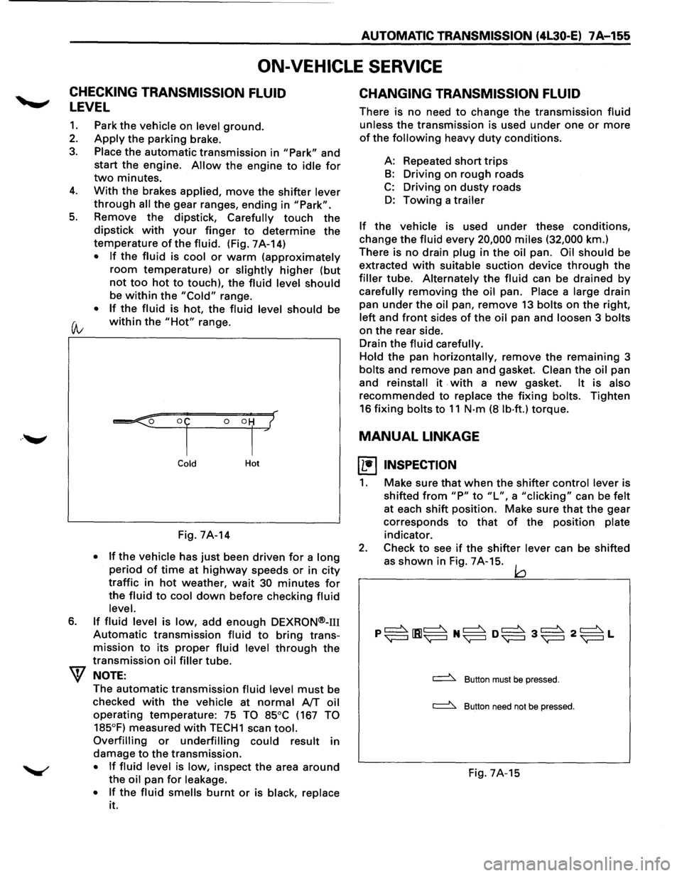
5. Remove the dipstick, Carefully touch the
dipstick with your finger to determine the
temperature of the fluid. (Fig. 7A-14)
• If the fluid is cool or warm (approximately
room temperature) or slightly higher (but
not too hot to touch), the fluid level should
be within the "Cold" range.
• If the fluid is hot, the fluid level should be
(A; within the "Hot" range.
6.
Cold Hot
Fig. 7A-14
• If the vehicle has just been driven for a long
period of time at highway speeds or in city
traffic in hot weather, wait 30 minutes for
the fluid to cool down before checking fluid
level.
If fluid level is low, add enough DEXRON®-m
Automatic transmission fluid to bring trans
mission
to its proper fluid level through the
transmission oil filler tube.
NOTE:
The automatic transmission fluid level must be
checked
with the vehicle at normal AfT oil
operating temperature: 75 TO 85°C (167 TO
185°F)
measured with TECH1 scan tool.
Overfilling or underfilling could result in
damage
to the transmission.
• If fluid level is low, inspect the area around
the oil pan for leakage.
•
If the fluid smells burnt or is black, replace
it.
CHANGING TRANSMISSION FLUID
There is no need to change the transmission fluid
unless the transmission is used under one or more
of the following heavy duty conditions.
A: Repeated
short trips
B: Driving on rough roads
C: Driving on dusty roads
D: Towing a trailer
If the vehicle is used under these conditions,
change the fluid every 20,000 miles (32,000 km.)
There is
no drain plug in the oil pan. Oil should be
extracted
with suitable suction device through the
filler tube. Alternately the fluid can be drained by
carefully removing the oil pan. Place a large drain
pan
under the oil pan, remove 13 bolts on the right,
left and front sides of the oil pan and loosen 3 bolts
on the rear side.
Drain
the fluid carefully.
Hold
the pan horizontally, remove the remaining 3
bolts and remove pan and gasket. Clean the oil pan
and
reinstall it . with a new gasket. It is also
recommended to replace the fixing bolts. Tighten
16 fixing bolts to 11 N·m (8 lb·ft.) torque.
MANUAL LINKAGE
~ INSPECTION
1. Make sure that when the shifter control lever is
shifted
from "P" to "L", a "clicking" can be felt
at each shift position. Make sure that the gear
corresponds
to that of the position plate
indicator.
2. Check to see if the shifter lever can be shifted
as
shown in Fig. 7A-15. jQ
~ Button must be pressed.
~ Button need not be pressed.
Fig. 7A-15