bolt pattern ISUZU TROOPER 1995 Workshop Manual
[x] Cancel search | Manufacturer: ISUZU, Model Year: 1995, Model line: TROOPER, Model: ISUZU TROOPER 1995Pages: 1928
Page 263 of 1928
4. Side bearing outer race
3. Differential cage assembly
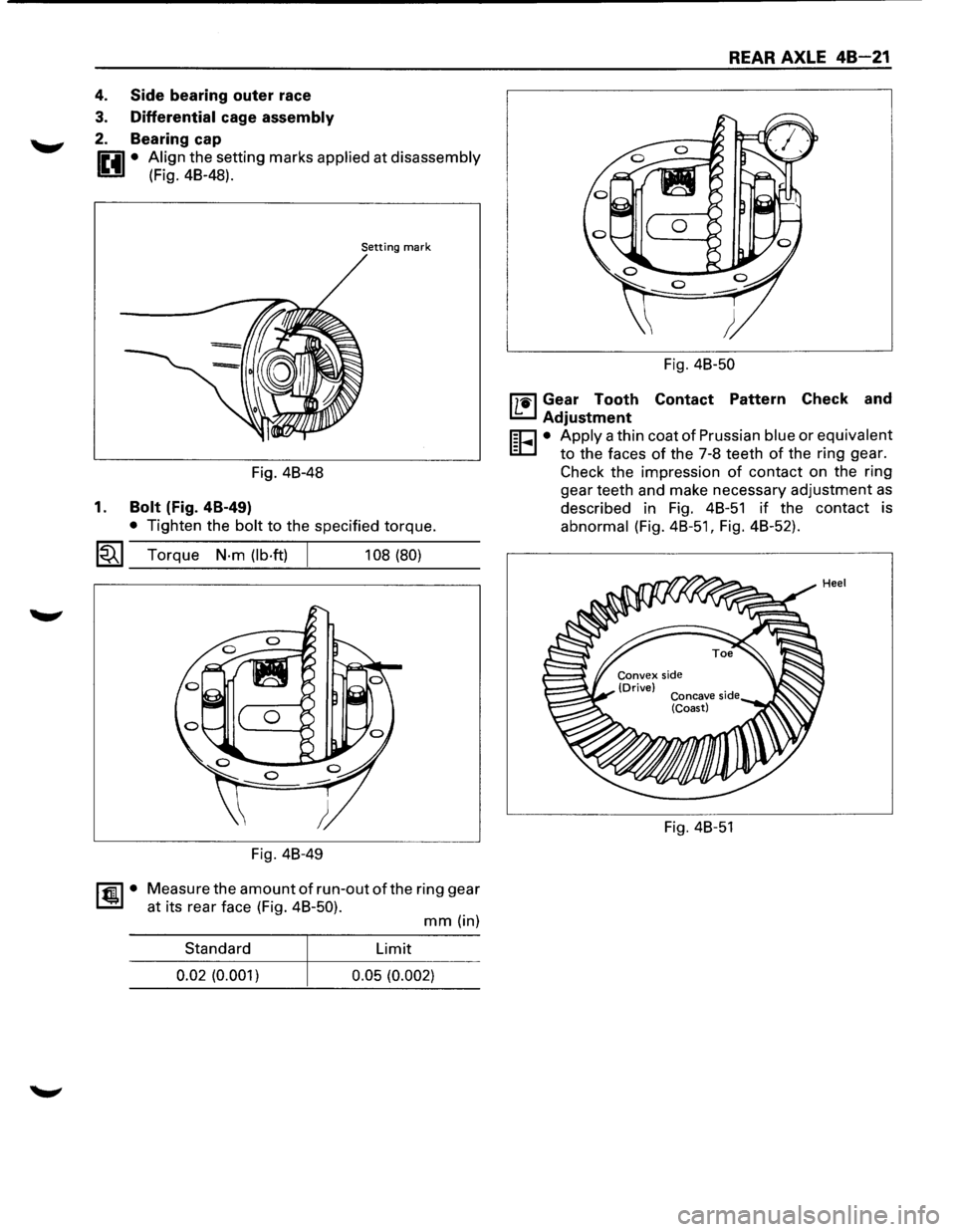
2. Bearing cap
0 • Align the setting marks applied at disassembly
1!!:!.1 (Fig. 48-48).
Setting mark
Fig. 48-48
1. Bolt (Fig. 4B-49)
• Tighten the bolt to the specified torque.
~~~ Torque N·m (lb·ft) 108 (80)
Fig. 48-49
~·
Measure the amount of run-out of the ring gear
at its rear face (Fig. 48-50).
mm (in)
Standard Limit
0.02 (0.001)
0.05 (0.002)
REAR AXLE 48-21
Fig. 48-50
l'7'1il Gear Tooth Contact Pattern Check and
I.£..J Adjustment
r;o • Apply a thin coat of Prussian blue or equivalent
EC.I to the faces of the 7-8 teeth of the ring gear.
Check the impression
of contact on the ring
gear teeth and make necessary adjustment
as
described in Fig. 48-51 if the contact is
abnormal (Fig.
48-51, Fig. 48-52).
Fig. 48-51
Page 300 of 1928
4C-22 FRONT DRIVING AXLE
7. Side bearing outer race
6. Differential cage assembly
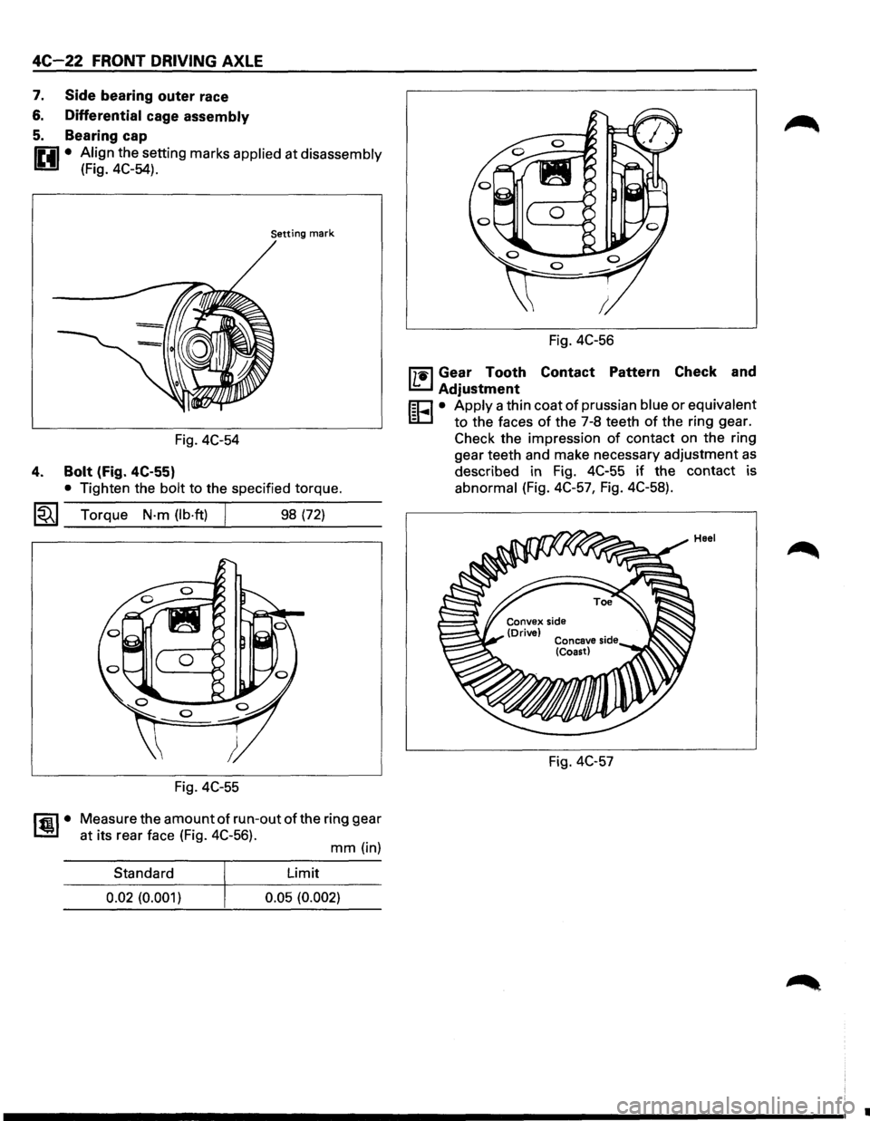
5. Bearing cap
IP.il • Align the setting marks applied at disassembly
U (Fig. 4C-54).
Setting mark
Fig. 4C-54
4. Bolt (Fig. 4C-55)
• Tighten the bolt to the specified torque.
~~~ Torque N·m (lb·ft) 98 (72)
Fig. 4C-55
~·
Measure the amount of run-out of the ring gear
at its rear face (Fig. 4C-56).
mm (in)
Standard Limit
0.02
(0.001) 0.05 (0.002)
Fig. 4C-56
mil Gear Tooth Contact Pattern Check and
I.!:::..J Adjustment
r;o • Apply a thin coat of prussian blue or equivalent
ID to the faces of the 7-8 teeth of the ring gear.
Check the impression
of contact on the ring
gear teeth and make necessary adjustment
as
described in Fig. 4C-55 if the contact is
abnormal (Fig. 4C-57, Fig. 4C-58).
Fig. 4C-57
•
Page 543 of 1928
l•!•l REASSEMBL V
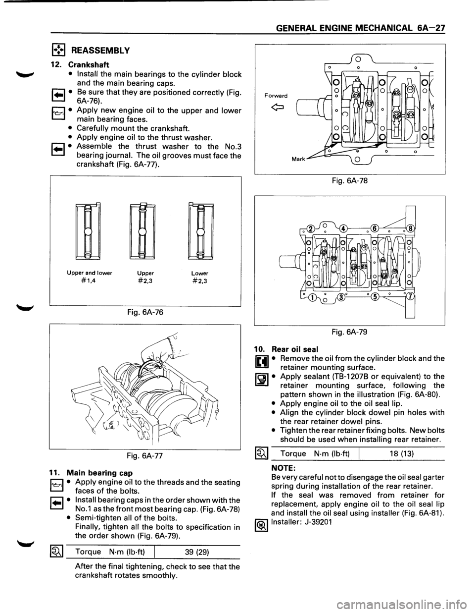
12. Crankshaft
• Install the main bearings to the cylinder block
and the main bearing caps.
1 .. 1• Be sure that they are positioned correctly (Fig.
6A-76).
1~1· Apply new engine oil to the upper and lower
main bearing faces.
• Carefully mount the crankshaft.
• Apply engine oil to the thrust washer.
1 .. 1• Assemble the thrust washer to the No.3
bearing
journal. The oil grooves must face the
crankshaft (Fig. 6A-77).
Upper and lower
#1.4
~
~
IH
t=
Upper
#2,3
Fig. 6A-76
Fig. 6A-77
11. Main bearing cap
Lower
#2,3
B • Apply engine oil to the
threads and the seating
' faces
of the bolts.
r=1 • Install bearing caps in the order shown with the
L:::.l No.1 as the front most bearing cap. (Fig. 6A-78)
• Semi-tighten all of the bolts.
Finally,
tighten all the bolts to specification in
the
order shown (Fig. 6A-79).
1~1 Torque N·m (lb·ft) 39 (29)
After the final tightening, check to see that the
crankshaft rotates
smoothly.
GENERAL ENGINE MECHANICAL 6A-27
Forward
Fig. 6A-78
Fig. 6A-79
10. Rear oil seal
liill • Re~ove the oil_from the cylinder block and the
U retainer mounting surface.
rEil • Apply sealant (TB-1207B or equivalen_t) to the
1.:::!!.1 retainer mounting surface, follow~ng the
pattern shown in the
illustration (Fig. 6A-80).
• Apply engine oil to the oil seal lip.
• Align
the cylinder block dowel pin holes with
the rear retainer dowel pins.
• Tighten the rear retainer fixing bolts. New bolts
should
be used when installing rear retainer.
~~~ Torque N·m (lb·ft) 18 (13)
NOTE:
Be very careful notto disengage the oil seal garter
spring during
installation of the rear retainer.
If the seal was removed from retainer for
replacement, apply engine oil to the oil seal lip
and install the oil seal using installer (Fig. 6A-81).
l®llnstaller: J-39201
Page 1061 of 1928
AUTOMATIC TRANSMISSION (4L30·E) 7A-189
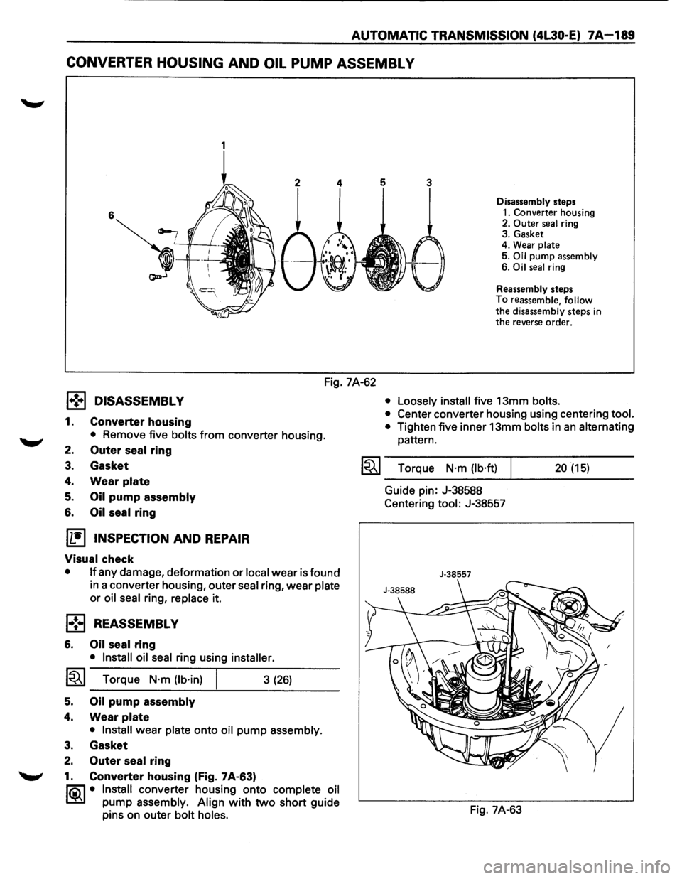
CONVERTER HOUSING AND OIL PUMP ASSEMBL V
1
Disassembly steps
1. Converter housing
2. Outer seal ring
3. Gasket
4. Wear
plate
5. Oil pump assembly
6. Oil seal ring
Reassembly steps
To reassemble, follow
the disassembly steps in the reverse order.
Fig. 7A-62
l•!•l DISASSEMBLY
1. Converter housing
• Remove five bolts from converter housing.
2. Outer seal ring
3. Gasket
4. Wear plate
5. Oil pump assembly
6. Oil seal ring
[1!) INSPECTION AND REPAIR
Visual check
• If any damage, deformation or local wear is found
in a converter housing, outer
seal ring, wear plate
or oil seal ring, replace it.
l•!•l REASSEMBLY
6. Oil seal ring
• Install oil seal ring using installer.
1~1 Torque N·m (lb·in)
5. Oil pump assembly
4. Wear plate
3 (26)
• Install wear plate onto oil pump assembly.
3. Gasket
2. Outer seal ring
"-"' 1. Converter housing (Fig. 7A-63)
li0\1 • Install converter housing onto complete oil
~ pump assembly. Align with two short guide
pins on outer
bolt holes. •
Loosely install
five 13mm bolts.
•
Center converter housing using centering tool.
•
Tighten five inner 13mm bolts in an alternating
pattern.
I~I ___ T_o_rq~u_e __ N_·_m_(_lb_·ft_)~l _____ 2_0_(_15_) ____ _
Guide pin: J-38588
Centering
tool: J-38557
J-38557
Fig. 7A-63