water pump ISUZU TROOPER 1995 Workshop Manual
[x] Cancel search | Manufacturer: ISUZU, Model Year: 1995, Model line: TROOPER, Model: ISUZU TROOPER 1995Pages: 1928
Page 21 of 1928
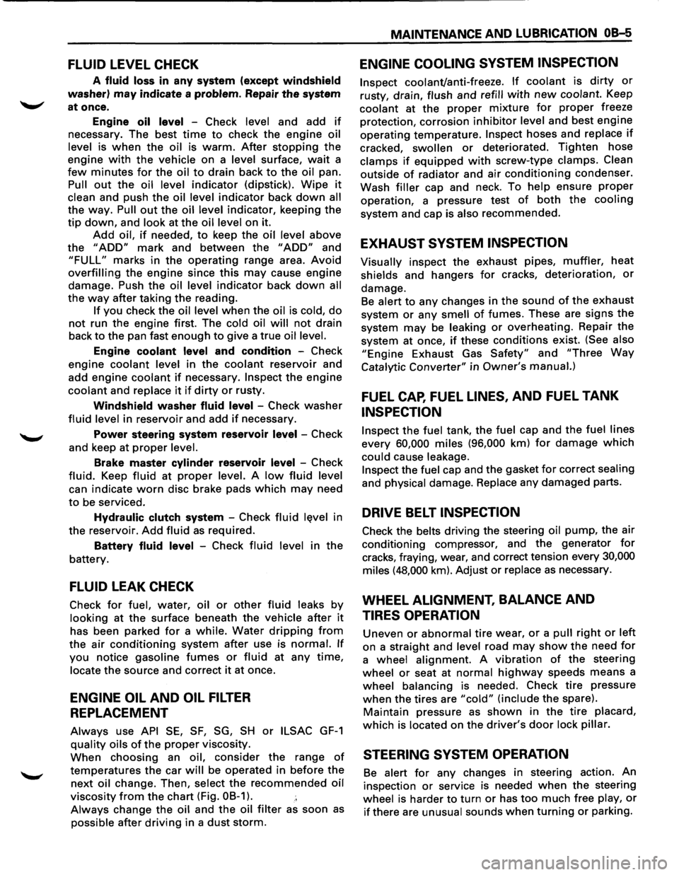
FLUID LEVEL CHECK
A fluid loss in any system (except windshield
washer) may indicate a problem. Repair the system
at once.
Engine
oil level -Check level and add if
necessary. The best time to check the engine oil
level is
when the oil is warm. After stopping the
engine with the vehicle on a level surface, wait a
few minutes for the oil to drain back to the oil pan.
Pull
out the oil level indicator (dipstick). Wipe it
clean and push the oil level indicator back down all
the
way. Pull out the oil level indicator, keeping the
tip down, and look at the oil level on it.
Add oil, if needed, to keep the oil level above
the
"ADD" mark and between the "ADD" and
"FULL" marks in the operating range area. Avoid
overfilling the engine since this may cause engine
damage. Push
the oil level indicator back down all
the
way after taking the reading.
If you check the oil level when the oil is cold, do
not run the engine first. The cold oil will not drain
back
to the pan fast enough to give a true oil level.
Engine coolant level and condition -Check
engine coolant level in the coolant reservoir and
add engine
coolant if necessary. Inspect the engine
coolant and replace it if dirty or rusty.
Windshield washer fluid level -Check washer
fluid level in reservoir and add if necessary.
Power steering system reservoir level-Check
and keep at
proper level.
Brake master cylinder reservoir level -Check
fluid. Keep fluid at proper level. A low fluid level
can indicate
worn disc brake pads which may need
to be serviced.
Hydraulic clutch system -Check fluid l~vel in
the reservoir.
Add fluid as required.
Battery fluid level -Check fluid level in the
battery.
FLUID LEAK CHECK
Check for fuel, water, oil or other fluid leaks by
looking at the surface beneath the vehicle after it
has been parked for a while. Water dripping from
the air conditioning system after use is normal. If
you notice gasoline fumes or fluid at any time,
locate the source and correct it at once.
ENGINE OIL AND OIL FILTER
REPLACEMENT
Always use API SE, SF, SG, SH or ILSAC GF-1
quality oils of the proper viscosity.
When choosing an oil, consider the range of
temperatures the car will be operated in before the
next oil change. Then, select the recommended oil
viscosity
from the chart (Fig. OB-1).
Always change the oil and the oil filter as soon as
possible after driving in a dust storm.
MAINTENANCE AND LUBRICATION OB-5
ENGINE COOLING SYSTEM INSPECTION
Inspect coolant/anti-freeze. If coolant is dirty or
rusty, drain, flush and refill with new coolant. Keep
coolant at the proper mixture for proper freeze
protection,
corrosion inhibitor level and best engine
operating temperature.
Inspect hoses and replace if
cracked, swollen or deteriorated. Tighten hose
clamps if equipped with screw-type clamps. Clean
outside of radiator and air conditioning condenser.
Wash
filler cap and neck. To help ensure proper
operation, a pressure test of both the cooling
system and cap is also recommended.
EXHAUST SYSTEM INSPECTION
Visually inspect the exhaust pipes, muffler, heat
shields and hangers
for cracks, deterioration, or
damage.
Be alert to any changes in the sound of the exhaust
system
or any smell of fumes. These are signs the
system may be leaking or overheating. Repair the
system at once,
if these conditions exist. (See also
"Engine Exhaust Gas Safety" and "Three Way
Catalytic Converter" in Owner's manual.)
FUEL CAP, FUEL LINES, AND FUEL TANK
INSPECTION
Inspect the fuel tank, the fuel cap and the fuel lines
every
60,000 miles (96,000 km) for damage which
could cause leakage.
Inspect the fuel cap and the gasket for correct sealing
and physical damage. Replace any damaged parts.
DRIVE BELT INSPECTION
Check the belts driving the steering oil pump, the air
conditioning compressor, and the generator
for
cracks, fraying, wear, and correct tension every 30,000
miles (48,000 km). Adjust or replace as necessary.
WHEEL ALIGNMENT, BALANCE AND
TIRES OPERATION
Uneven or abnormal tire wear, or a pull right or left
on a straight and level road may show the need for
a wheel alignment. A vibration of the steering
wheel or seat at normal highway speeds means a
wheel balancing is needed. Check tire pressure
when the tires are "cold" (include the spare).
Maintain pressure as shown in the tire placard,
which is located on the driver's door lock pillar.
STEERING SYSTEM OPERATION
Be alert for any changes in steering action. An
inspection
or service is needed when the steering
wheel is harder
to turn or has too much free play, or
if there are unusual sounds when turning or parking.
Page 36 of 1928
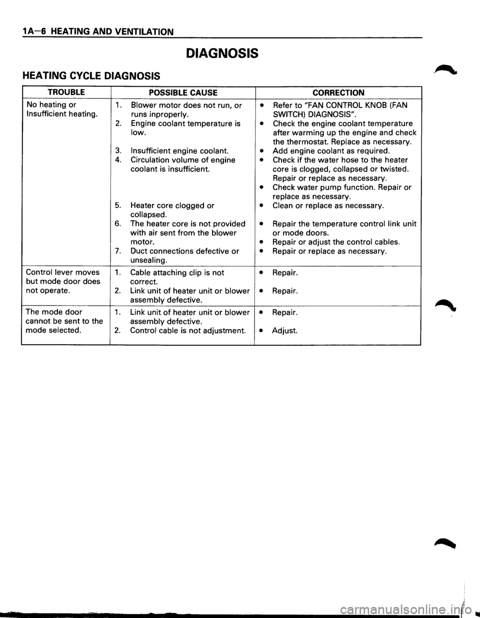
1A-6 HEATING AND VENTILATION
DIAGNOSIS
HEATING CYCLE DIAGNOSIS
TROUBLE POSSIBLE CAUSE CORRECTION
No heating or 1. Blower motor does not run, or • Refer to "FAN CONTROL KNOB (FAN
Insufficient heating.
runs inproperly. SWITCH) DIAGNOSIS".
2. Engine coolant temperature is • Check the engine coolant temperature
low. after warming up the engine and check
the thermostat.
Replace as necessary.
3. Insufficient engine coolant. • Add engine coolant as required .
4. Circulation volume of engine • Check if the water hose to the heater
coolant is insufficient. core is clogged, collapsed or twisted.
Repair
or replace as necessary.
• Check water pump function. Repair or
replace as necessary.
5. Heater core clogged or • Clean or replace as necessary.
collapsed.
6. The heater core is not provided • Repair the temperature control link unit
with air sent from the blower or mode doors.
motor.
• Repair or adjust the control cables.
7. Duct connections defective or • Repair or replace as necessary.
unsealing.
Control lever
moves 1. Cable attaching clip is not • Repair.
but
mode door does correct.
not operate. 2. Link unit of heater unit or blower • Repair.
assembly defective.
The
mode door 1. Link unit of heater unit or blower • Repair.
cannot
be sent to the assembly defective.
mode
selected. 2. Control cable is not adjustment. • Adjust.
_______ __... ..... ..._ ____________ (
Page 57 of 1928
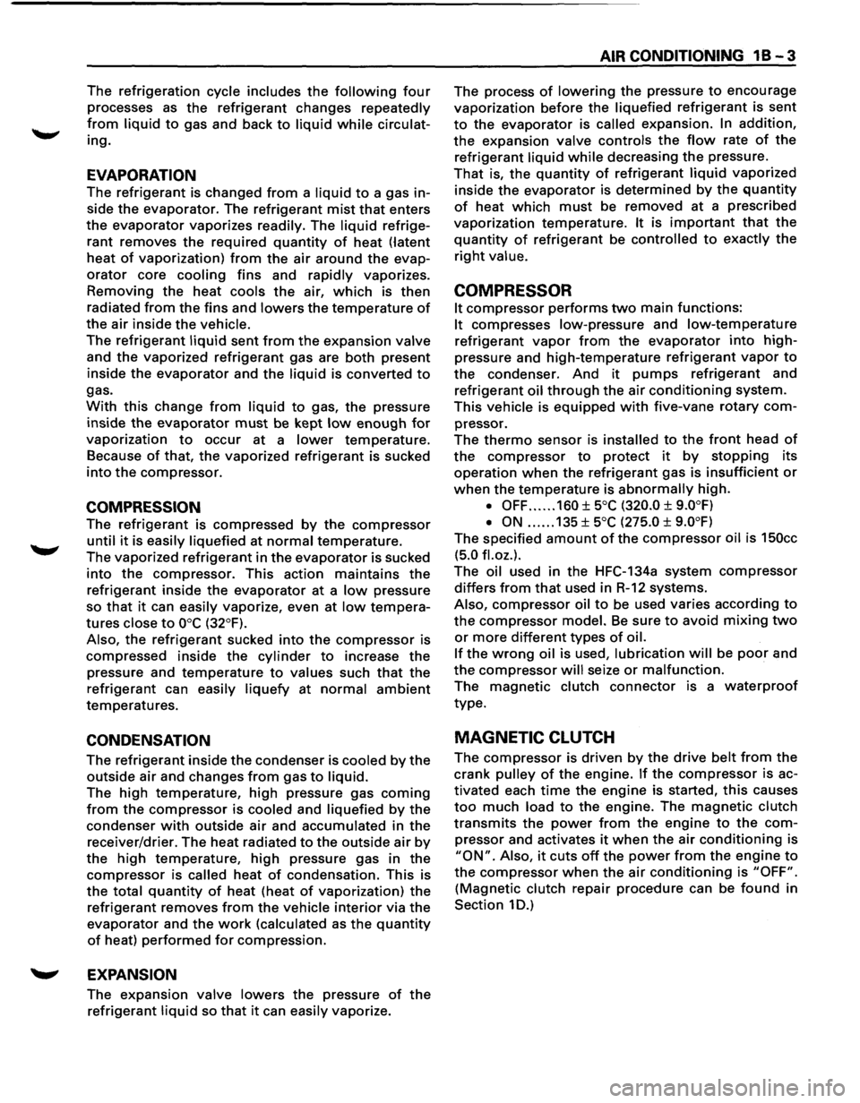
The refrigeration cycle includes the following four
processes as the refrigerant changes repeatedly
from liquid to gas and back to liquid while circulat
ing.
EVAPORATION
The refrigerant is changed from a liquid to a gas in
side
the evaporator. The refrigerant mist that enters
the evaporator vaporizes readily. The liquid refrige
rant removes
the required quantity of heat (latent
heat of vaporization) from the air around the evap
orator core cooling fins and rapidly vaporizes.
Removing the heat cools the air, which is then
radiated
from the fins and lowers the temperature of
the air inside the vehicle.
The refrigerant liquid sent from the expansion valve
and the vaporized refrigerant gas are both present
inside the
evaporator and the liquid is converted to
gas.
With this change from liquid to gas, the pressure
inside
the evaporator must be kept low enough for
vaporization to occur at a lower temperature.
Because of that, the vaporized refrigerant is sucked
into the compressor.
COMPRESSION
The refrigerant is compressed by the compressor
until it is easily liquefied at normal temperature.
The vaporized
refrigerant in the evaporator is sucked
into the compressor. This action maintains the
refrigerant inside the evaporator at a low pressure
so
that it can easily vaporize, even at low tempera
tures close to ooc (32°F).
Also, the refrigerant sucked into the compressor is
compressed inside the
cylinder to increase the
pressure and temperature to values such that the
refrigerant can easily liquefy at normal ambient
temperatures.
CONDENSATION
The refrigerant inside the condenser is cooled by the
outside air and changes from gas to liquid.
The high temperature, high pressure gas coming
from the compressor is cooled and liquefied by the
condenser with outside air and accumulated in the
receiver/drier. The heat radiated to the outside air by
the high temperature, high pressure gas in the
compressor is called heat of condensation. This is
the total quantity of heat (heat of vaporization) the
refrigerant removes
from the vehicle interior via the
evaporator and the work (calculated as the quantity
of heat) performed for compression.
'-' EXPANSION
The expansion valve lowers the pressure of the
refrigerant liquid so that it can easily vaporize.
AIR CONDITIONING 1 B -3
The process of lowering the pressure to encourage
vaporization before the
liquefied refrigerant is sent
to the evaporator is called expansion. In addition,
the expansion valve controls the flow rate of the
refrigerant liquid while decreasing the pressure.
That is, the quantity of refrigerant liquid vaporized
inside
the evaporator is determined by the quantity
of heat which must be removed at a prescribed
vaporization temperature.
It is important that the
quantity of refrigerant be controlled to exactly the
right value.
COMPRESSOR
It compressor performs two main functions:
It compresses low-pressure and low-temperature
refrigerant vapor from the evaporator into high
pressure and high-temperature
refrigerant vapor to
the condenser. And it pumps refrigerant and
refrigerant
oil through the air conditioning system.
This vehicle is equipped with five-vane rotary com
pressor.
The
thermo sensor is installed to the front head of
the compressor to protect it by stopping its
operation when the refrigerant gas is insufficient or
when the temperature is abnormally high.
• OFF ...... 160 ±soc (320.0 ± 9.0°F)
• ON
...... 135 ±soc (27S.O ± 9.0°F)
The specified amount of the compressor oil is 1SOcc
(S.O fl.oz.).
The oil used in the HFC-134a system compressor
differs from that used in R-12 systems.
Also, compressor oil to be used varies according to
the compressor model. Be sure to avoid mixing two
or more different types of oil.
If the wrong oil is used, lubrication will be poor and
the compressor will seize or malfunction.
The magnetic clutch connector is a waterproof
type.
MAGNETIC CLUTCH
The compressor is driven by the drive belt from the
crank
pulley of the engine. If the compressor is ac
tivated each
time the engine is started, this causes
too much load to the engine. The magnetic clutch
transmits the power from the engine to the com
pressor and activates it when the air conditioning is
"ON". Also, it cuts off the power from the engine to
the compressor when the air conditioning is "OFF".
(Magnetic clutch repair procedure can be found in
Section 1 D.)
Page 501 of 1928
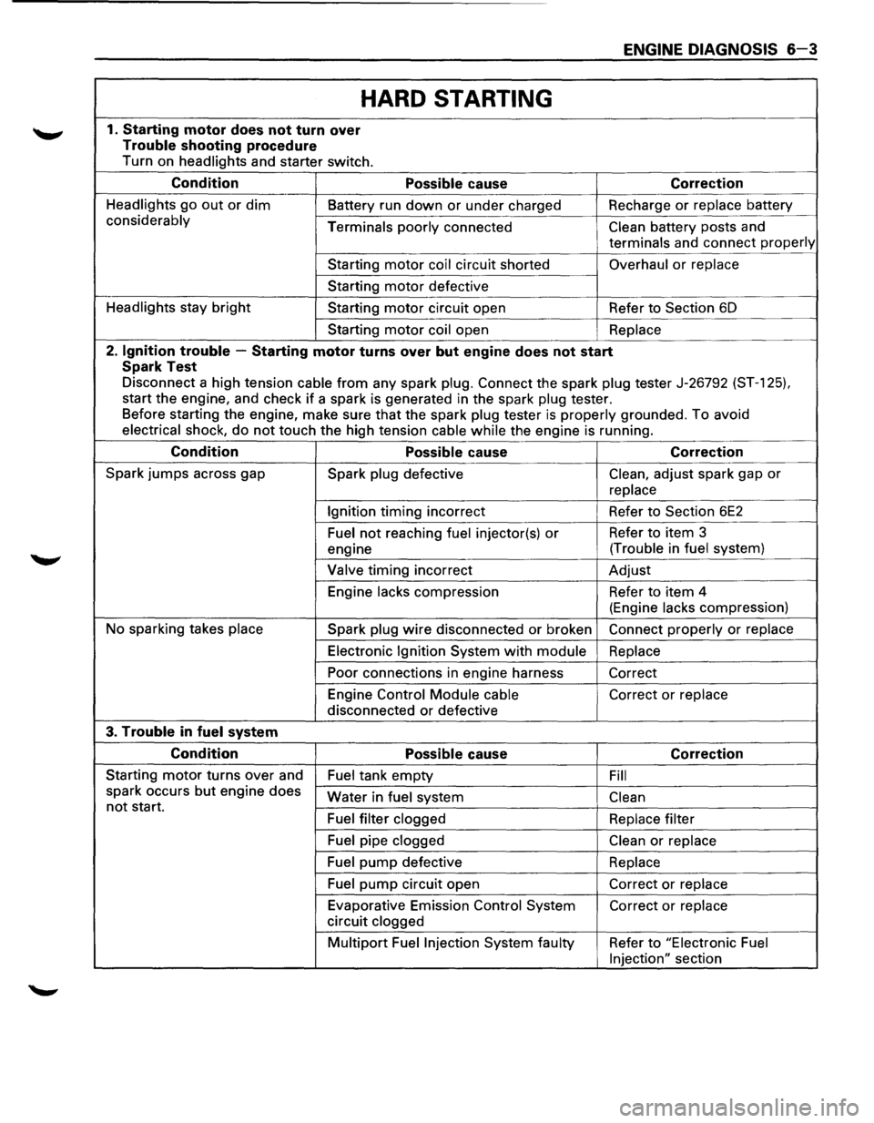
ENGINE DIAGNOSIS 6-3
HARD STARTING
1. Starting motor does not turn over
Trouble shooting procedure
Turn on headlights and starter switch.
Condition Possible cause Correction
Headlights go out or dim Battery run down or under charged Recharge or replace battery
considerably
Terminals poorly connected Clean battery posts and
terminals and connect properly
Starting motor coil circuit shorted Overhaul or replace
Starting motor defective
Headlights stay
bright Starting motor circuit open Refer to Section 6D
Starting
motor coil open Replace
2. Ignition trouble -Starting motor turns over but engine does not start
Spark Test
Disconnect a high tension cable from any spark plug. Connect the spark plug tester J-26792 (ST-1 25).
start the engine, and check if a spark is generated in the spark plug tester.
Before starting the engine, make sure
that the spark plug tester is properly grounded. To avoid
electrical shock, do not touch the high tension cable while the engine is running.
Condition Possible cause Correction
Spark jumps across gap
Spark plug defective Clean, adjust spark gap or
replace
Ignition
timing incorrect Refer to Section 6E2
Fuel not reaching fuel injector(s) or Refer to item 3
engine (Trouble
in
fuel system)
Valve
timing incorrect Adjust
Engine
lacks compression Refer to item 4
(Engine
lacks compression)
No sparking takes
place Spark plug wire disconnected or broken Connect properly or replace
Electronic Ignition System with module Replace
Poor connections in engine harness
Correct
Engine Control
Module cable Correct or replace
disconnected or defective
3. Trouble in fuel system
Condition Possible cause Correction
Starting motor turns over and
Fuel tank empty Fill
spark occurs but engine does
not start. Water in fuel system Clean
Fuel filter clogged Replace filter
Fuel pipe clogged Clean or replace
Fuel pump defective
Replace
Fuel
pump circuit open Correct or replace
Evaporative Emission Control System Correct or replace
circuit clogged
Multipart Fuel Injection System faulty Refer to "Electronic Fuel
Injection"
section
Page 506 of 1928
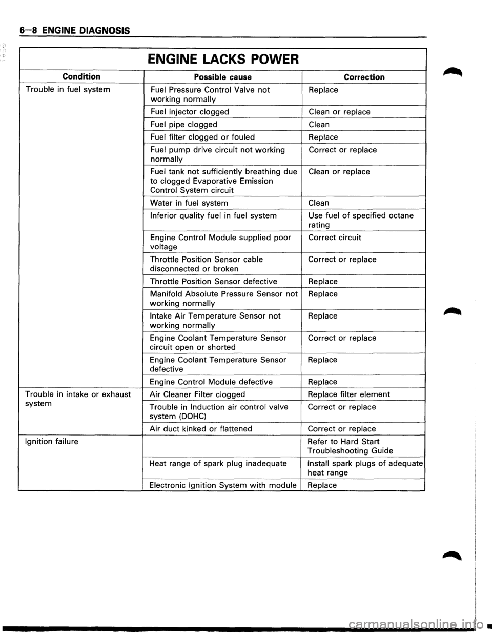
6-8 ENGINE DIAGNOSIS
ENGINE LACKS POWER
Condition
Possible cause Correction
Trouble in fuel system Fuel Pressure Control Valve not Replace
working normally
Fuel
injector clogged Clean or replace
Fuel
pipe clogged Clean
Fuel filter clogged
or fouled Replace
Fuel
pump drive circuit not working Correct or replace
normally
Fuel tank not sufficiently breathing due Clean or replace
to clogged Evaporative Emission
Control System circuit
Water in
fuel system Clean
Inferior quality fuel
in fuel system Use fuel of specified octane
rating
Engine
Control Module supplied poor Correct circuit
voltage
Throttle
Position Sensor cable Correct or replace
disconnected or broken
Throttle Position Sensor defective Replace
Manifold Absolute
Pressure Sensor not Replace
working normally
Intake Air Temperature Sensor not Replace
working normally
Engine Coolant Temperature Sensor Correct or replace
circuit open or shorted
Engine
Coolant Temperature Sensor Replace
defective
Engine
Control Module defective Replace
Trouble
in intake or exhaust Air Cleaner Filter clogged Replace filter element
system Trouble in Induction air control valve Correct or replace
system (DOHC)
Air duct kinked or flattened Correct or replace
Ignition failure
Refer to Hard Start
Troubleshooting Guide
Heat range
of spark plug inadequate Install spark plugs of adequate
heat range
Electronic Ignition System with module Replace
•
Page 509 of 1928
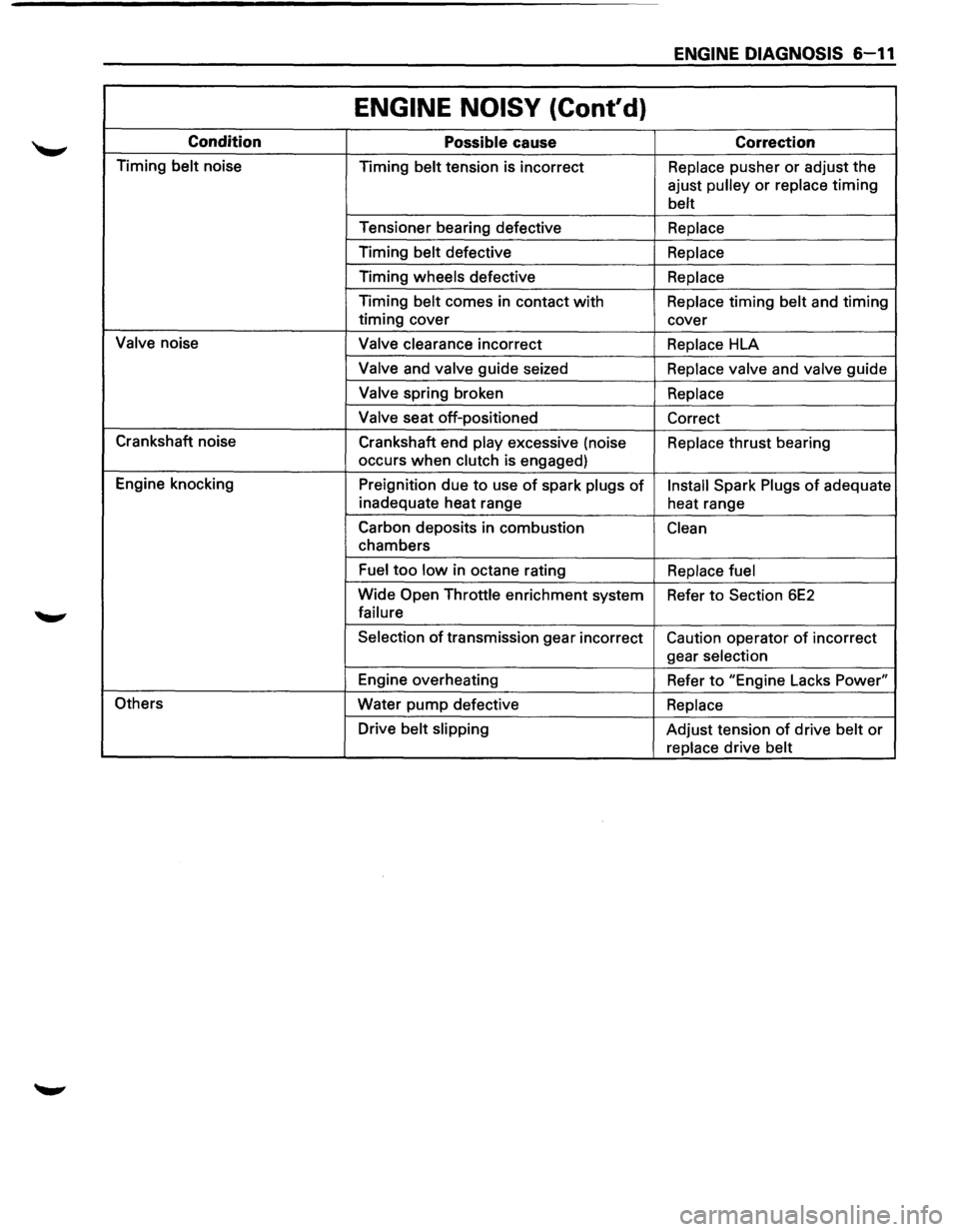
ENGINE DIAGNOSIS 6-11
ENGINE NOISY (Cont'd)
Condition Possible cause Correction
Timing belt noise
Timing belt tension is incorrect Replace pusher or adjust the
ajust
pulley or replace timing
belt
Tensioner bearing defective Replace
Timing belt defective Replace
Timing wheels defective Replace
Timing belt comes in contact with Replace timing belt and timing
timing cover
cover
Valve noise Valve clearance incorrect Replace HLA
Valve and valve guide seized Replace valve and valve guide
Valve spring broken Replace
Valve
seat off-positioned
Correct
Crankshaft noise
Crankshaft end
play excessive (noise Replace thrust bearing
occurs
when clutch is engaged)
Engine knocking
Preignition due
to use of spark plugs of Install Spark Plugs of adequate
inadequate heat range
heat range
Carbon deposits in combustion
Clean
chambers
Fuel too low in octane rating Replace fuel
Wide Open Throttle enrichment system
Refer to Section 6E2
failure
Selection
of transmission gear incorrect Caution operator of incorrect
gear
selection
Engine overheating
Refer to "Engine Lacks Power"
Others Water
pump defective Replace
Drive belt slipping Adjust tension of drive belt or
replace drive belt
Page 580 of 1928
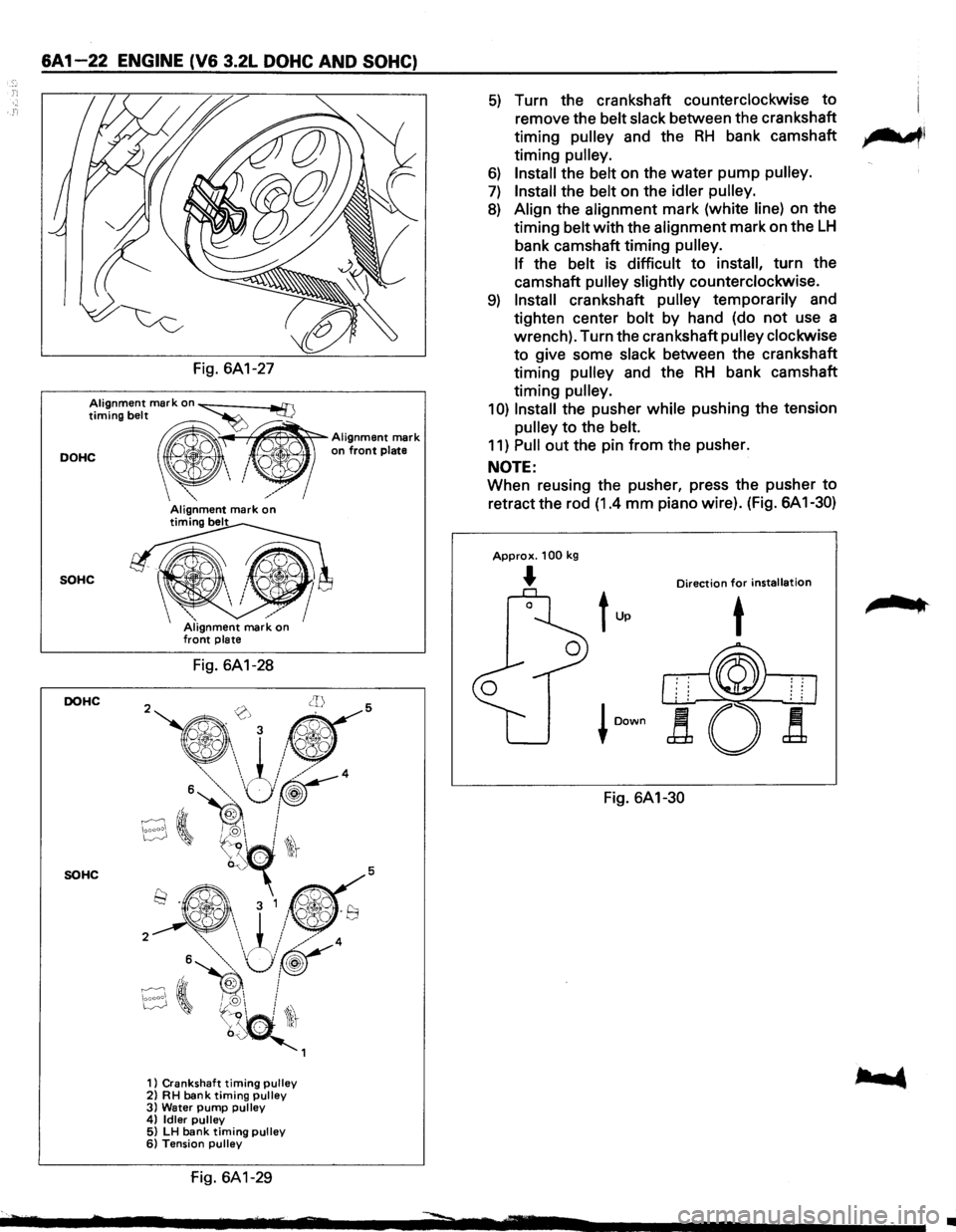
&A 1-22 ENGINE (V& 3.2L DOHC AND SOHC)
Fig. 6A1-27
Alignment mark on ~ timing belt ~
DOHC " ' on front plate
~~
Alignment mark
_","'
SOHC
DOHC
SOHC
/ Alignment mark on timing belt
Fig. 6A1-28
1) Crankshaft timing pulley 2) RH bank timing pulley 3) Water pump pulley 4) Idler pulley 5) LH bank timing pulley 6) Tension pulley
fig. 6A1-29
5) Turn the crankshaft counterclockwise to
remove the belt slack between the crankshaft
timing
pulley and the RH bank camshaft ,.......,,
timing pulley.
6) Install the belt on the water pump pulley.
7) Install the belt on the idler pulley.
8) Align the alignment mark (white line) on the
timing belt with the alignment mark on the
LH
bank camshaft timing pulley.
If
the belt is difficult to install, turn the
camshaft
pulley slightly counterclockwise.
9) Install crankshaft pulley temporarily and
tighten center bolt by hand (do
not use a
wrench). Turn the crankshaft
pulley clockwise
to give some slack between the crankshaft
timing
pulley and the RH bank camshaft
timing
pulley.
1 0) Install the pusher while pushing the tension
pulley to the belt.
11) Pull out the pin from the pusher.
NOTE:
When reusing the pusher, press the pusher to
retract the rod (1.4 mm piano wire). (Fig. 6A 1-30)
Approx. 100 kg
... Direction for installation
Fig. 6A1-30
,.. ..
•
Page 629 of 1928
ENGINE COOLING 68-1
SECTION 68
ENGINE COOLING
CONTENTS
General Description . . . . . . . . . . . . . . . . . . . . . . . . . . 68-1 Radiator . . . . . . . . . . . . . . . . . . . . . . . . . . . . . . . . . . . . . . 68-7
Diagnosis........................................ 68-3 Drive Belt Adjustment . . . . . . . . . . . . . . . . . . . . 68-1 0
On-Vehicle Service............................ 68-4 Main Data and Specifications .............. 68-12
Water Pump . . . . . . . . . . . . . . . . . . . . . . . . . . . . . . . . 68-4
Thermostat . . . . . . . . . . . . . . . . . . . . . . . . . . . . . . . . . . 68-6
Torque Specifications .................... 68-12
Special Tools ................................... 68-13
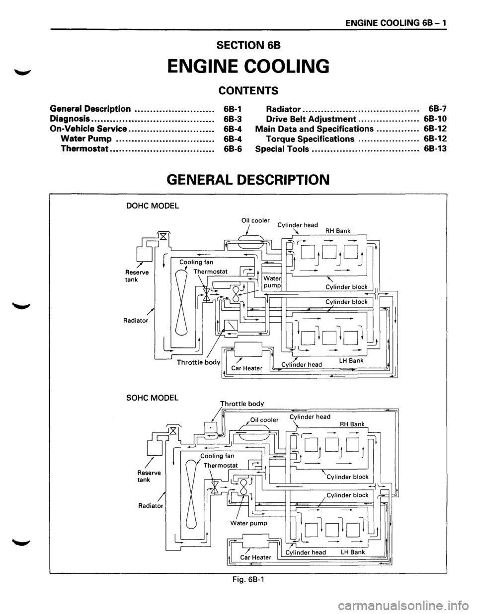
GENERAL DESCRIPTION
DOHC MODEL
Reserve tank
/ Radiator
SOHC MODEL
Radiator
Oil cooler
Throttle body
Fig. 68-1
Cylinder head
"'
RH Bank
' Cylinder bloc~~
Cylinder block
LH Bank
Cylinder block
~
lololol ~ I
~L: - -~,t
Cylinder head LH Bank d
d
Page 630 of 1928
68 - 2 ENGINE COOLING
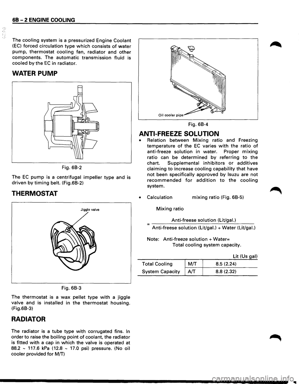
The cooling system is a pressurized Engine Coolant
(EC) forced circulation type which consists of water
pump, thermostat cooling fan, radiator and other
components. The automatic transmission fluid is
cooled by the EC in radiator.
WATER PUMP
Fig. 68-2
The
EC pump is a centrifugal impeller type and is
driven by timing belt. (Fig.68-2)
THERMOSTAT
Jiggle valve
Fig. 68-3
The
thermostat is a wax pellet type with a jiggle
valve and is installed in the thermostat housing.
(Fig.68-3)
RADIATOR
The radiator is a tube type with corrugated fins. In
order to raise the boiling point of coolant, the radiator
is fitted
with a cap in which the valve is operated at
88.2
-117.6 kPa (12.8 - 17.0 psi) pressure. (No oil
cooler
provided for M!f)
Fig. 68-4
ANTI-FREEZE SOLUTION
•
•
Relation between Mixing ratio and Freezing
temperature
of the EC varies with the ratio of
anti-freeze solution in water. Proper mixing
ratio can be determined by referring to the
chart. Supplemental inhibitors or additives
claiming to increase cooling capability that have
not been specifically approved by lsuzu are not
recommended for addition to the cooling
system.
Calculation mixing ratio (Fig. 68-5)
Mixing ratio
Anti-freese
solution (Lit/gal.) =-----------------Anti-freese solution (Lit/gal.) +Water (Lit/gal.)
Note: Anti-freeze solution +Water=
Total cooling system capacity.
Lit (Us
gal)
Total Cooling
M!f 8.5 (2.24) ~-~~--------System Capacity AfT 8.8 (2.32)
Page 632 of 1928
68 - 4 ENGINE COOLING
ON-VEHICLE SERVICE
DRAINING AND REFILLING COOLING
SYSTEM
Before draining the cooling system, inspect the sys
tem and perform any necessary service to ensure that
it is clean, does not leak and is in proper working
order. The Engine Coolant (EC) level should be be
tween the "MIN" and "MAX" lines of reserve tank
when the engine is cold. If low, check for leakage and
add
EC up to the "MAX" line. There should not be any
excessive deposit of rust or scales around the radiator
cap
or radiator filler hole, and the EC should also be
free
from oil. Replace the EC if excessively dirty.
1. Completely drain the cooling system by opening
the drain petcock at the bottom of the radiator.
2. Remove the radiator cap.
W WARNING
To avoid the danger of being burned, do not
remove the cap while the engine and radiator
are still hot. Scalding fluid and steam can be
blown out under pressure.
3. Disconnect all hoses from the EC reserve tank.
Scrub and clean the inside of the reserve tank with
soap and water. Flush it well with clean water,
then drain it. Install the reserve tank and hoses.
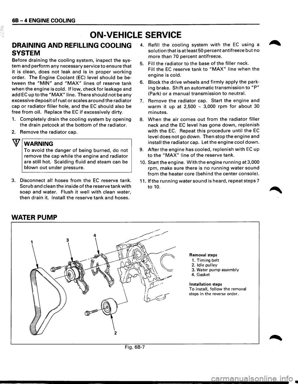
WATER PUMP
3
j
2
4. Refill the cooling system with the EC using a
solution that is at least 50 percent antifreeze but no
more than 70 percent antifreeze.
5. Fill the radiator to the base of the filler neck.
Fill the EC reserve tank to "MAX" line when the
engine is cold.
6. Block the drive wheels and firmly apply the park
ing brake.
Shift an automatic transmission to "P"
(Park) or a manual transmission to neutral.
7. Remove the radiator cap. Start the engine and
warm it up at 2,500 -3,000 rpm for about 30
minutes.
8. When the air comes out from the radiator filler
neck and the EC level has gone down, replenish
with the EC. Repeat this procedure until the EC
level does not go down. Then stop the engine and
install the radiator cap. Let the engine cool down.
9. After the engine has cooled, replenish with EC up
to the "MAX" line of the reserve tank.
10. Start the engine. With the engine running at 3,000
rpm, make sure there is no running water sound
from the heater core (behind the center console).
11. If the running water sound is heard, repeat steps 7
to 10.
Removal steps
1. Timing
belt 2. Idle pulley 3. Water pump assembly
4. Gasket
Installation steps To install, follow the removal steps in the reverse order.
Fig. 6B-7
•