flat tire ISUZU TROOPER 1995 Owner's Manual
[x] Cancel search | Manufacturer: ISUZU, Model Year: 1995, Model line: TROOPER, Model: ISUZU TROOPER 1995Pages: 1928
Page 323 of 1928
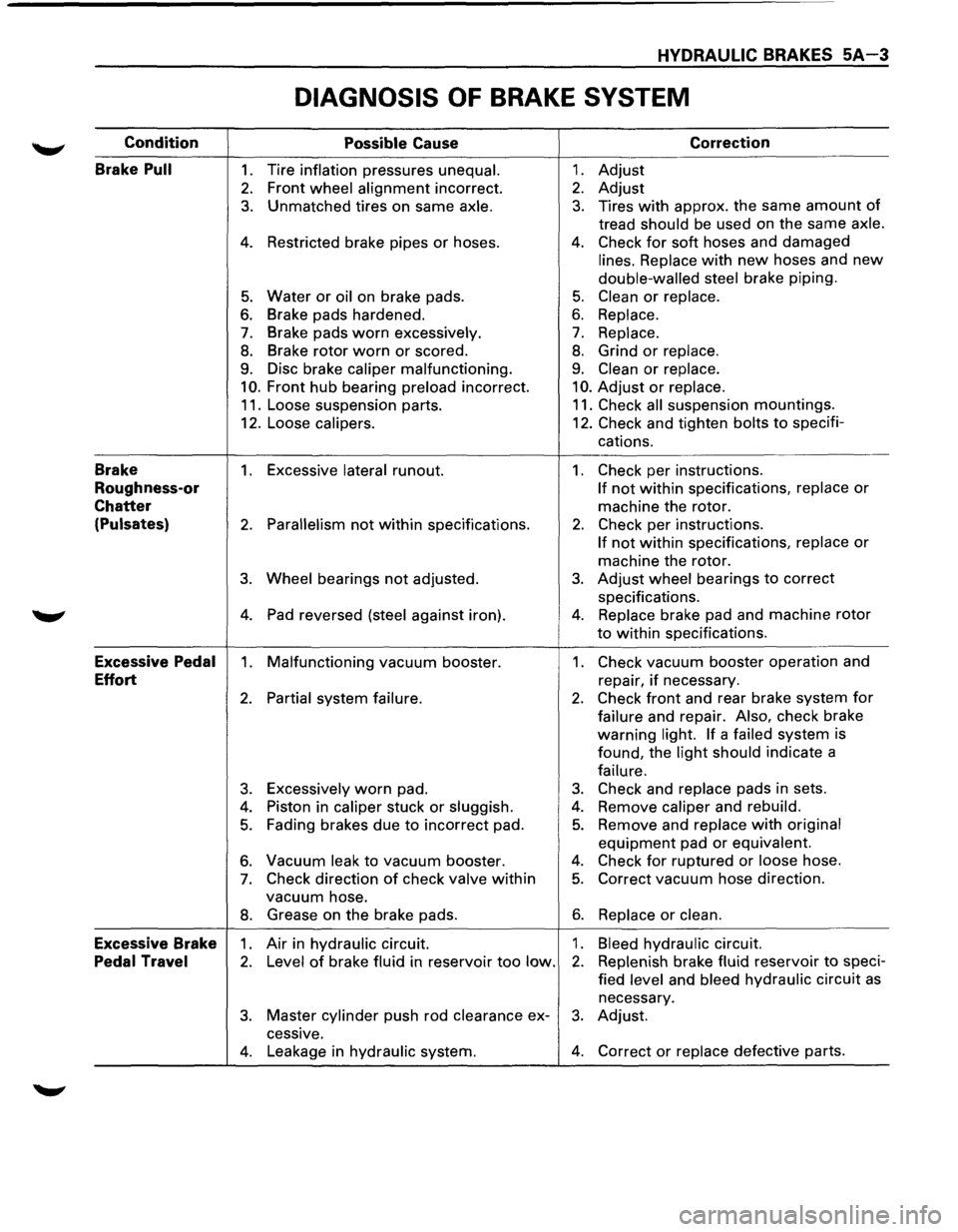
HYDRAULIC BRAKES 5A-3
DIAGNOSIS OF BRAKE SYSTEM
Condition
Possible Cause Correction
Brake
Pull 1. Tire inflation pressures unequal. 1. Adjust
2. Front wheel alignment incorrect. 2. Adjust
3. Unmatched tires on same axle. 3. Tires with approx. the same amount of
tread should be used on the same axle.
4. Restricted brake pipes or hoses. 4. Check for soft hoses and damaged
lines. Replace with new hoses and new
double-walled steel brake piping.
5. Water or oil on brake pads. 5. Clean or replace.
6. Brake pads hardened. 6. Replace.
7. Brake pads worn excessively. 7. Replace.
8. Brake rotor worn or scored. 8. Grind or replace.
9. Disc brake caliper malfunctioning. 9. Clean or replace.
10. Front hub bearing preload incorrect. 10. Adjust or replace.
11. Loose suspension parts. 11. Check all suspension mountings.
12. Loose
calipers. 12. Check and tighten bolts to specifi-
cations.
Brake 1. Excessive lateral runout. 1. Check per instructions.
Roughness-or If not within specifications, replace or
Chatter machine the rotor.
(Pulsates) 2. Parallelism not within specifications. 2. Check per instructions.
If not within specifications, replace or
machine the rotor.
3. Wheel bearings not adjusted. 3. Adjust wheel bearings to correct
specifications.
4. Pad reversed (steel against iron). 4. Replace brake pad and machine rotor
to within specifications.
Excessive Pedal 1. Malfunctioning vacuum booster. 1. Check vacuum booster operation and
Effort repair, if necessary.
2. Partial system failure. 2. Check front and rear brake system for
failure and repair. Also, check brake
warning
light. If a failed system
is
found, the
light should indicate a
failure.
3. Excessively worn pad. 3. Check and replace pads in sets.
4. Piston in caliper stuck or sluggish. 4. Remove caliper and rebuild.
5. Fading brakes due to incorrect pad. 5. Remove and replace with original
equipment pad or equivalent.
6. Vacuum leak to vacuum booster. 4. Check for ruptured or loose hose.
7. Check direction of check valve within 5. Correct vacuum hose direction.
vacuum hose.
8. Grease on the brake pads. 6. Replace or clean.
Excessive Brake 1. Air in hydraulic circuit. 1. Bleed hydraulic circuit.
Pedal Travel 2. Level of brake fluid in reservoir too low. 2. Replenish brake fluid reservoir to speci-
fied
level and bleed hydraulic circuit as
necessary.
3. Master cylinder push rod clearance ex-3. Adjust.
cessive.
4. Leakage in hydraulic system. 4. Correct or replace defective parts.
Page 331 of 1928
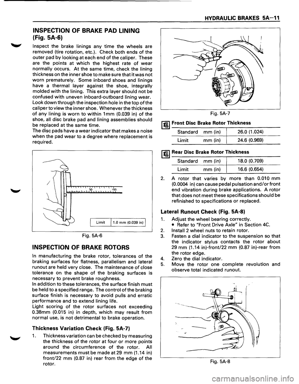
INSPECTION OF BRAKE PAD LINING
(Fig. SA-6)
Inspect the brake linings any time the wheels are
removed (tire rotation, etc.). Check both ends
of the
outer pad by
looking at each end of the caliper. These
are the points at which the highest rate
of wear
normally occurs. At the same time, check the lining
thickness on the inner shoe to make sure that it was not
worn prematurely. Some inboard shoes and linings
have a thermal layer against the shoe, integrally
molded
with the lining. This extra layer should not be
confused with uneven inboard-outboard lining wear.
Look
down through the inspection hole in the top of the
caliper to view the inner shoe. Whenever the thickness
of any lining is worn to within 1 mm (0.039 in) of the
shoe,
all disc brake pad and lining assemblies should
be replaced at the same time.
The disc pads have a
wear indicator that makes a noise
when the pad wear to a degree where replacement is
required.
100
Limit 11.0 mm (0.039 in) I
Fig. 5A-6
INSPECTION OF BRAKE ROTORS
In manufacturing the brake rotor, tolerances of the
braking surfaces
for flatness, parallelism and lateral
runout are held very close. The maintenance of close
tolerance
on the shape of the braking surfaces is
necessary to prevent brake roughness.
In addition to these tolerances, the surface finish must
be held to a specified range. The control ofthe braking
surface finish is necessary to avoid
pulls and erratic
performance and to extend
lining life.
Light scoring of the rotor surfaces not exceeding
0.38mm (0.015 in) in depth, which may result from
normal use, is not detrimental to brake operation.
Thickness Variation Check (Fig. 5A-7)
1. Thickness variation can be checked by measuring
the thickness
of the rotor at four or more points
around the circumference
of the rotor. All
measurements must be made at 29 mm (1.14 in)
front/22 mm (0.87 in) rear from the edge of the
rotor.
HYDRAULIC BRAKES 5A-11
Fig. 5A-7
~~~ Front Disc Brake Rotor Thickness
Standard mm (in) 26.0 (1.024)
Limit mm(in) 24.6 (0.969)
~~~Rear Disc Brake Rotor Thickness
Standard mm (in) 18.0 (0.709)
Limit mm (in) 16.6 (0.654)
2. A rotor that varies by more than 0.010 mm
(0.0004 in) can cause pedal pulsation and/or front
end vibration during brake applications. A rotor
that does not meet these specifications should be
refinished
to specifications or replaced.
Lateral Runout Check (Fig. 5A-8)
1. Adjust the wheel bearing correctly.
• Refer to "Front Drive Axle" in Section 4C.
2. Install 2 wheel nuts to retain rotor.
3. Fasten a dial indicator to the suspension so that
the indicator stylus contacts the rotor about
29 mm (1.14 in)-front/22 mm (0.87 in)-rear from
the rotor edge.
4. Zero the dial indicator.
5. Move the rotor one complete revolution and
observe
total indicated runout.
Fig. 5A-8
Page 507 of 1928
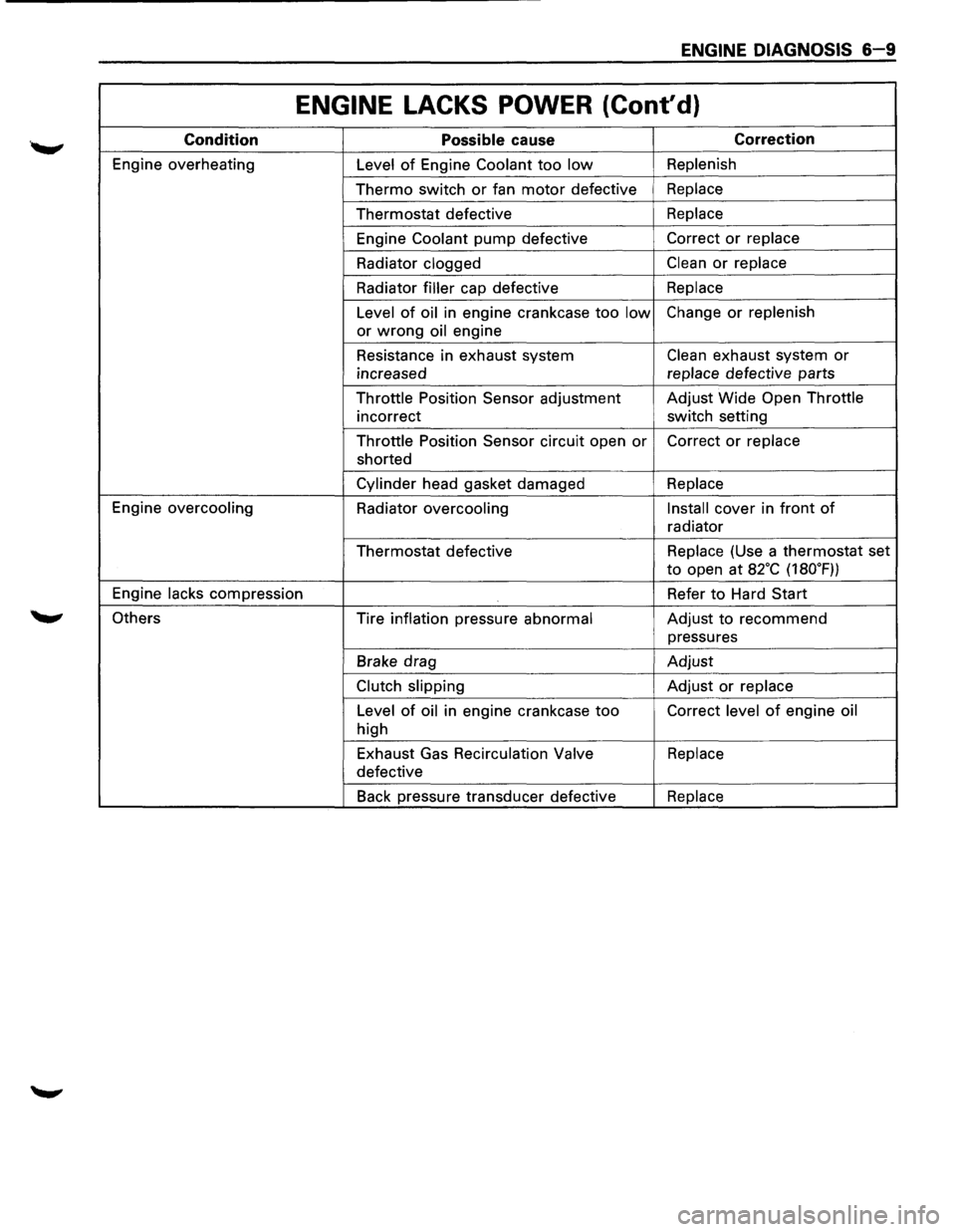
ENGINE DIAGNOSIS 6-9
ENGINE LACKS POWER (Cont'd)
Condition Possible cause Correction
Engine overheating
Level of Engine Coolant too low Replenish
Thermo switch or fan motor defective Replace
Thermostat defective Replace
Engine
Coolant pump defective Correct or replace
Radiator clogged
Clean or replace
Radiator
filler cap defective Replace
Level
of oil in engine crankcase too low Change or replenish
or
wrong oil engine
Resistance in exhaust system
Clean exhaust system or
increased replace
defective parts
Throttle Position Sensor adjustment Adjust
Wide Open Throttle
incorrect switch setting
Throttle Position Sensor circuit open
or Correct or replace
shorted
Cylinder head gasket damaged Replace
Engine overcooling
Radiator
overcooling Install cover
in front of
radiator
Thermostat defective Replace
(Use a thermostat set
to open at a2·c (180.F))
Engine
lacks compression Refer to Hard Start
Others Tire inflation pressure
abnormal Adjust to recommend
pressures
Brake drag Adjust
Clutch slipping Adjust or replace
Level
of oil in engine crankcase too Correct level of engine oil
high
Exhaust Gas
Recirculation Valve Replace
defective
Back pressure transducer defective
Replace
Page 1142 of 1928
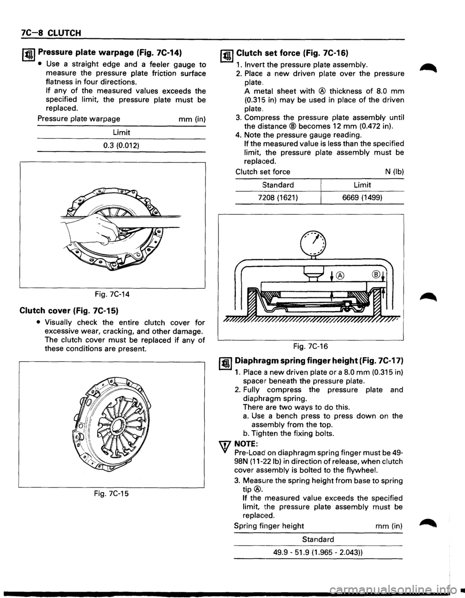
7C-8 CLUTCH
I~U Pressure plate warpage (fig. 7C-14)
• Use a straight edge and a feeler gauge to
measure the pressure plate friction surface
flatness in
four directions.
If any of the measured values exceeds the
specified limit, the pressure plate
must be
replaced.
Pressure plate warpage
Limit
0.3 (0.012)
Fig. 7C-14
Clutch cover (fig. 7C-15)
mm (in)
• Visually check the entire clutch cover for
excessive wear, cracking, and other damage.
The clutch cover
must be replaced if any of
these conditions are present.
Fig. 7C-15
jQI Clutch set force (Fig. 7C-16)
1. Invert the pressure plate assembly.
2. Place a new driven plate over the pressure
plate.
A metal sheet
with @ thickness of 8.0 mm
(0.315 in) may be used in place of the driven
plate
..
3. Compress the pressure plate assembly until
the
distance® becomes 12 mm (0.472 in).
4. Note the pressure gauge reading.
If the measured value is less than the specified
limit, the pressure plate assembly
must be
replaced.
Clutch set force N (lb)
Standard Limit
7:208 (1621) 6669 (1499)
Fig. 7C-16
1•1 Diaphragm spring finger height (fig. 7C-17)
1. Place a new driven plate or a 8.0 mm (0.315 in)
spacer beneath the pressure plate.
2. Fully compress the pressure plate and
diaphragm spring.
There are
two ways to do this.
a. Use a bench press to press down on the
asst~mbly from the top.
b. Tighten the fixing bolts.
IDNOTE:
Yf Pre-Load on diaphragm spring finger must be 49-
98N
(11-~~2 lb) in direction of release, when clutch
cover
assembly is bolted to the flywheel.
3. Measure the spring height from base to spring
tip@.
If the measured value exceeds the specified
limit, the pressure plate assembly
must be
replaced.
Spring finger height
mm (in)
Standard
49.9 -51.9 (1.965 -
2.043))
•
Page 1262 of 1928
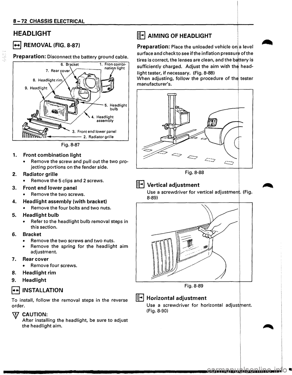
8 -72 CHASSIS ELECTRICAL
HEADLIGHT
E) REMOVAL (FIG. 8-87)
Preparation: Disconnect the battery ground cable.
Fig. 8-87
1. Front combination light
• Remove the screw and pull out the two pro
jecting
portions on the fender side.
2. Radiator grille
• Remove the 5 clips and 2 screws.
3. Front end lower panel
• Remove the two screws.
4. Headlight assembly (with bracket)
• Remove the four bolts and two nuts.
5. Headlight bulb
• Refer to the headlight bulb removal steps in
this section.
6. Bracket
• Remove the two screws and two nuts.
• Remove the spring for the headlight aim
adjustment.
7. Rear cover
• Remove four screws.
8. Headlight rim
9. Headlight
E3 INSTALLATION
To install, follow the removal steps in the reverse
order.
W CAUTION:
After installing the headlight, be sure to adjust
the headlight aim.
(E AIMING OF HEADLIGHT
Preparation: Place the unloaded vehicle on a level
surface and check to see ifthe inflation pressur oft he
tires is correct, the lenses are clean, and the b ttery is
sufficiently charged.
Adjust the aim with th head
light tester, if necessary. (fig. 8-88)
When adjusting,
follow the procedure of th tester
manufacturer's.
Fig. 8-88
1~1 .... 1 Vertical adjustment
Use a screwdriver for vertical adjustmen . (Fig.
8-89)
Fig. 8-89
m .... l Horizontal adjustment
Use a screwdriver for horizontal adjust ent.
(Fig.
8-90)
..
Page 1509 of 1928
![ISUZU TROOPER 1995 Owners Manual (1!] ON-VEHICLE SERVICE
"-"" Check the meter display accuracy and the operation
of the odometer with the speedometer tester.
\f CAUTION:
Inappropriate tire inflation may affect the accu
rac](/img/61/57183/w960_57183-1508.png "ISUZU TROOPER 1995 Owners Manual (1!] ON-VEHICLE SERVICE
\"-\"\" Check the meter display accuracy and the operation
of the odometer with the speedometer tester.
\f CAUTION:
Inappropriate tire inflation may affect the accu
rac")
(1!] ON-VEHICLE SERVICE
"-"" Check the meter display accuracy and the operation
of the odometer with the speedometer tester.
\f CAUTION:
Inappropriate tire inflation may affect the accu
racy
of the odometer.
(To
conductthis test, refer to the tester manufac
turer's instruction manual.)
IGN GND
SEN
CHASSIS ELECTRICAL 8-319
(MPH)
Tester display speed Meter
display permissible
level
20 18.3-21.7
40 38.3-41.7
60 58.3-61.7
80 78.8-82.8
100 98.8-102.8
120 118.5-123.1
NOTE: Since the meter display permissible levels
above are specifications solely
for the
meter,
they are to be used as reference
values when conducting on-vehicle service.
~ INDIVIDUAL INSPECTION
I t!!.l Remove the speedometer from the meter
assembly and measure the resistance and the
current consumption between each terminal.
(Fig. 8-347)
Replace the speedometer
when the result of
inspection is found abnormal.
Resistance value
Red(+) Black(-) Black(-) Red(+)
IGN GND IGN GND IGN-GND 00 30.6-37.4k
SEN GND SEN GND SEN-GND 28.8-35.2k 00
4P GND 4P GND 4P-GND 13.5 -16.5k 00
Note: Use the
analog type circuit tester (range: x 1k)
Current value
Terminal
symbol
IGN-GND
~ 8
Current
consumption
85 ± 15mA Remarks
(when
12 ± 1V No signal input
applied)
Note: 1. Use the analog type circuit tester.
2. Since the current consumption fluctuates
when the source voltage varies, check
to
be sure that the voltage applied is 12V ± 1 V.
Fig. 8-347
Page 1636 of 1928
9J-12 Supplemental Restraint System
REPAIRS AND INSPECTIONS REQUIRED AFTER AN
ACCIDENT
NOTE
• If
any SRS components are damaged, they must be
replaced. If SRS component mounting points are
damaged, they must be
replaced.
•
Never use SRS parts from another vehicle. This
does not
include remanufactured parts purchased
from an authorized
dealer; they may be used for SRS
repairs.
• Do not attempt to service discriminating sensors, the
dual pole arming sensor, the DERM, the SRS coil
assembly,
or the inflator modules. Service of these
items is by
replacement only.
•
Verify the part number of replacement inflator
modules.
CAUTION: PROPER OPERATION OF THE
SENSORS AND SUPPLEMENTAL RESTRAINT
SYSTEM (SRS) REQUIRES THAT ANY REPAIRS TO
THE VEHICLE STRUCTURE RETURN IT TO THE
ORIGINAL PRODUCTION CONFIGURATION.
DEPLOYMENT REQUIRES, AT A MINIMUM,
REPLACEMENT OF THE SENSORS, THE INFLATOR
MODULE,
AND DIMENSIONAL INSPECTION OF THE
STEERING COLUMN. ANY VISIBLE DAMAGE TO
THE DERM MOUNTING BRACKET(S) REQUIRES
REPLACEMENT, SENSORS MUST BE REPLACED,
AND THE
STEERING COLUMN MUST BE
DIMENSIONALLY INSPECTED, WHETHER
DEPLOYMENT
OCCURRED OR NOT.
ACCIDENT WITH DEPLOYMENT-COMPONENT
REPLACEMENT AND
INSPECTIONS
Certain SRS components must be replaced for damage
after a
frontal crash involving air bag deployment. Those
components are:
• Inflator modules.
• All
sensors. It is include among the Dual pole Arming
Sensor.
CAUTION
•
Refer to "Sensor Replacement Guidelines"
below for Important Information on sensor
replacement In both deployment and
non-deployment crashes.
• SRS coil assembly, Inspect wiring and connector for
any signs of scorching,
melting, or damage due to
excessive heat.
Replace if damaged. Refer to this in
section
3.
ACCIDENT WITH OR WITHOUT DEPLOYMENT
COMPONENT INSPECTIONS
Certain SRS and restraint system components must be
inspected after any crash, whether the air bag
deployed
or not. Those components are:
• Steering column-Dimensionally inspect per
"Checking Steering Column for Accident Damage" in
section 3.
• Sensors, if in the area of accident damage. If with
deployment, All sensors must be replaced.
CAUTION
•
Refer to "Sensor Replacement Guidelines"
below for Important information on sensor
replacement in both deployment and
non-deployment crashes.
• Knee bolsters and mounting points-Inspect for any
distortion, bending, cracking, or other damage.
• 1/P steering column reinforcement plate-Inspect for
any distortion, bending, cracking, or other damage.
• liP braces-Inspect for any distortion, bending,
cracking, or other damage.
~
• Seat belts and mounting points-Refer to "Seat Belts"
in SECTION 10.
SENSOR REPLACEMENT GUIDELINES
SRS sensor replacement policy requires replacement of
the all sensors, after crash Involving Air Bag
Deployment.
WIRING DAMAGE
If any SRS wire harness is damaged, it should be
replaced. Don't repair SRS HARNESS. It is replace only.
SRS CONNECTOR {PLASTIC BODY AND
TERMINAL METAL PIN) DAMAGE
If any connector or terminal in the SRS wire harness
(except
pigtails) is damaged, it should be replaced.
SRS WIRE PIGTAIL DAMAGE
If the wiring pigtail (a wire or wires attached directly to the
device,
not by a connector)is damaged, the entire
component(with pigtail)must be replaced. Examples of
"pigtail" components are the driver inflator module, the
passenger
inflator module, the discriminating sensors,
the
dual pole arming sensor and the SRS coil assembly. ~
SRS WIRE DAMAGE
If any wire except the pigtail is damaged, the wire should
be replaced.
Ill
Page 1640 of 1928
9J-16 Supplemental Restraint ~
DEPLOYMENT OUTSIDE VEHICLE (DRIVER
INFLATOR
MODULE)
Deployment outside the vehicle is proper when the
vehicle is to be returned to service. This includes, for
example, situations in which the vehicle will be returned
to
useful service after a functionally or cosmetically
deficient
inflator module is replaced. Deployment and
disposal of a malfunctioning inflator module is, of course,
subject to any required retention period.
For deployment of a
live (undeployed) inflator module
outside the vehicle, the deployment procedure must be
followed exactly. Always wear safety glasses during this
deployment procedure
until a deployed inflator module is
scrapped
or until an undeployed inflator module is
shipped. Before performing the procedures, you
should
be familiar with servicing the SRS and with proper
handling of the inflator module. Procedures should be
read fully before they are performed.
The following procedure requires use of J-41434
SRS
deployment harness with appropriate pigtail adapter. Do
not attempt procedure without J-41434 adapter.
WARNING: FAILURE TO FOLLOW PROCEDURES
IN
THE ORDER LISTED MAY RESULT IN PERSONAL
INJURY.
NEVER CONNECT DEPLOYMENT
HARNESS TO ANY POWER SOURCE BEFORE
CONNECTING DEPLOYMENT HARNESS TO THE
DRIVER INFLATOR MODULE. DEPLOYMENT
HARNESS SHALL REMAIN SHORTED AND NOT BE ~
CONNECTED TO A POWER SOURCE UNTIL THE
AIR BAG IS TO BE DEPLOYED. THE INFLATOR
MODULE WILL IMMEDIATELY DEPLOY THE AIR
BAG WHEN A POWER SOURCE IS CONNECTED TO
IT. WEAR SAFETY GLASSES THROUGHOUT THIS
ENTIRE DEPLOYMENT AND DISPOSAL
PROCEDURE.
NOTE
• This information applies only to driver inflator
modules. Refer to "Deployment Outside
Vehicle(Passenger Inflator Module)" in this section
for information on passenger inflator module
scrapping.
1. Turn ignition switch to "LOCK," remove key and put
on safety glasses.
2. Inspect J-41434 SRS Deployment Harness and
appropriate
pigtail adapter for damage. If harness or
pigtail adapter is damaged, discard and obtain a
replacement.
•
Page 1643 of 1928
~ Supplemental Restraint System 9J-19
26. Temporarily store the driver inflator module with its inflator module can be found in the applicable service
vinyl trim cover facing
up, away from the surface manual or in a service bulletin.
upon which is rests.
27.
Call the Technical Assistance group for further
assistance.
DEPLOYMENT OUTSIDE VEHICLE
(PASSENGER INFLATOR MODULE)
WARNING: FAILURE TO FOLLOW PROPER SRS
INFLATOR MODULE DISPOSAL PROCEDURES
CAN RESULT IN AIR BAG DEPLOYMENT WHICH
MAY CAUSE PERSONAL INJURY. UNDEPLOYED
INFLATOR MODULES MUST NOT BE DISPOSED OF
THROUGH NORMAL REFUSE CHANNELS. THE
UNDEPLOYED INFLATOR MODULE CONTAINS
SUBSTANCES
THAT CAN CAUSE SEVERE ILLNESS
OR
PERSONAL INJURY IF THE SEALED
CONTAINER IS DAMAGED DURING DISPOSAL.
DISPOSAL
IN ANY MANNER INCONSISTENT WITH
PROPER PROCEDURES MAY BE A VIOLATION OF
FEDERAL, STATE AND/OR LOCALLAWS.
Deployment out of the vehicle is proper when the vehicle
is to be returned to service. This includes, for example,
situations
in which a functionally or cosmetically deficient
inflator module
is replaced. Deployment and disposal of
an inflator module is, of course, subject to any required
reterntion period.
For deployment
of a live inflator module out of the
·'-" vehicle, the deployment procedure must be followed
exactly.
ALWAYS wear safety glasses during this
deployment procedure until the deployed inflator module
is scrapped. Before performing the procedures you
should
be familiar with servicing the SRS system and
with proper handling of the inflator module. Procedures
should be read fully before they are performed.
The following procedure requires use of J-41434
SIR
Deployment Harness with the appropriate pigtail
adapter. The procedure also requires the use of J-41497
Passenger
Side SRS Module Deployment Fixture. Do
not attempt this procedure without J-41434 and adapter,
and J-41497.
WARNING: FAILURE TO FOLLOW PROCEDURES
IN THE ORDER LISTED MAY RESULT IN PERSONAL
INJURY.
NEVER CONNECT DEPLOYMENT
HARNESS TO ANY POWER SOURCE BEFORE
CONNECTING DEPLOYMENT HARNESS TO THE
INFLATOR MODULE. DEPLOYMENT HARNESS
SHALL REMAIN SHORTED AND NOT BE
CONNECTED TO A POWER SOURCE UNTIL THE
AIRBAG IS TO BE DEPLOYED. THE INFLATOR
MODULE WILL IMMEDIATELY DEPLOY THE
AIRBAG WHEN A POWER SOURCE IS CONNECTED
TO IT. WEAR SAFETY GLASSES THROUGHOUT
THIS ENTIRE DEPLOYMENT AND DISPOSAL
~ PROCEDURE.
NOTE: This information applies only to passenger
inflator modules. Information for disposing of a live driver
1. Turn ignition switch to "LOCK", remove key, and put
on safety glasses.
2. Inspect J-41434 SRS Deployment Harness and
appropriate pigtail adapter for damage.
If harness or
pigtail is damaged, discard and obtain a
replacement.
Page 1646 of 1928
9J-22 Supplemental Restraint System
AIR BAG TO EXPAND IN THE UNLIKELY EVENT OF
ACCEIDENTAL DEPLOYMENT. FAILURE TO
FOLLOW PROCEDURES MAY RESULT IN
PERSONAL INJURY.
26. Temporarily store the inflator module with the bag
facing up, away from the surface upon which it rests.
27.
Call the Technical Assistance group for further
assistance.
DEPLOYMENT INSIDE VEHICLE(VEHICLE
SCRAPPING PROCEDURE)
Deployment inside vehicle is proper when the vehicle is
to be destroyed or
salvaged for component parts. This
includes, but is not limited to, the following situations.
1. The vehicle has completed its useful life.
2. The vehicle has been damaged beyond repair in a
non-deployment type accident.
3. The vehicle has been stripped or damaged beyond
repair
in a theft.
4. The vehicle will be salvaged for component parts to
be
used on a vehicle with a different Vehicle
Identification Number (VIN) as opposed to being
rebuilt as same VIN. Never use SRS components
from another
vehicle. This is done to ensure SRS
system integrity since only new SRS system
components.
WARNING: FAILURE TO FOLLOW PROPER SRS
INFLATOR MODULE DISPOSAL PROCEDURES
CAN RESULT IN AIR BAG DEPLOYMENT WHICH
MAY CAUSE PERSONAL INJURY. UNDEPLOYED
INFLATOR MODULES MUST NOT BE DISPOSED OF
THROUGH NORMAL REFUSE CHANNELS. THE
UNDEPLOYED INFLATOR MODULE CONTAINS
SUBSTANCES THAT CAL CAUSE SEVERE ILLNESS
OR
PERSONAL INJURY IF THE SEALED
CONTAINER IS DAMAGED DURING DISPOSAL.
DISPOSAL IN ANY MANNER INCONSISTENT WITH
PROPER PROCEDURES MAY BE A VIOLATION OF
FEDERAL, STATE AND/OR LOCAL LAWS.
1. Turn ignition switch to "LOCK," remove key and put
on safety glasses.
2. Remove all loose objects from front seats.
3. Disconnect driver inflator module, yellow 3-way
connector located at the base of the steering column.
4. Cut the driver inflator module yellow 2-way harness
connector from the
vehicle leaving at least 16 cm(six
inches) of wire at the connector.
5. Strip 13 mm(1/2 inch) of insulation from each wire
lead of the connector.
6. Cut two 900 cm(30 feet) deployment wires from
0.8mm2(18 gauge) or thicker
multi-strand wire. These
wires
will be used to fabricate the driver
deployment harness.
7. Strip 13 mm(1/2 inch) of insulation from both ends of
the wires cut
in the previous step.
8. Short the wires by twisting together one end from
each. Deployment wires
shall remain shorted and
not
be connected to a power source until the air bag
is to be
deployed.
WARNING: FAILURE TO
FOLLOW PROCEDURES
IN
THE ORDER LISTED COULD RESULT IN
PERSONAL INJURY. NEVER CONNECT
DEPLOYMENT WIRES TO ANY POWER SOURCE
BEFORE CONNECTING DEPLOYMENT WIRES TO
THE INFLATOR MODULE LEADS. DEPLOYMENT
WIRES SHALL REMAIN SHORTED AND NOT BE
CONNECTED TO A POWER SOURCE UNTIL THE
AIR BAG IS TO BE DEPLOYED. THE INFLATOR
MODULE WILL IMMEDIATELY DEPLOY THE AIR
BAG WHEN A POWER SOURCE IS CONNECTED TO
IT. WEAR SAFETY GLASSES THROUGHOUT THIS
ENTIRE DEPLOYMENT AND DISPOSAL
PROCEDURE.
9. Twist together one connector wire lead to one
deployment wire. The connection should be
mechanically secure.
10. Bend twisted connection made in the previous step
flat and wrap tightly with electrical tape to insulate ~
and secure.
11. Twist together, bend and tape the remaining
connector wire lead to the remaining deployment
wire.
12. Connect the deployment harness to the driver
inflator module, yellow 2-way connector at the base
of the steering
column. Route deployment harness
out the driver side of the
vehicle.
WARNING:
DEPLOYMENT WIRES SHALL REMAIN
SHORTED
AND NOT BE CONNECTED TO A POWER
SOURCE UNTIL THE AIR BAG IS TO BE DEPLOYED.
THE INFLATOR MODULE WILL IMMEDIATELY
DEPLOY THE AIR BAG WHEN A POWER SOURCE IS
CONNECTED TO IT.
CONNECTING THE DEPLOYMENT WIRES TO THE
POWER
SOURCE SHOULD ALWAYS BE THE FINAL
STEP IN
THE INFLATOR MODULE DEPLOYMENT
PROCEDURE. FAILURE TO FOLLOW
PROCEDURES IN THE ORDER LISTED COULD
RESULT IN PERSONAL INJURY.
13. Disconnect passenger inflator module, yellow 2-way
connector located behind 1/P compartment door
assembly.
14. Cut the passenger inflator module harness
connector from the vehicle leaving at least 16 cm(six
inches) of wire at the connector).