flat tire ISUZU TROOPER 1995 Workshop Manual
[x] Cancel search | Manufacturer: ISUZU, Model Year: 1995, Model line: TROOPER, Model: ISUZU TROOPER 1995Pages: 1928
Page 28 of 1928
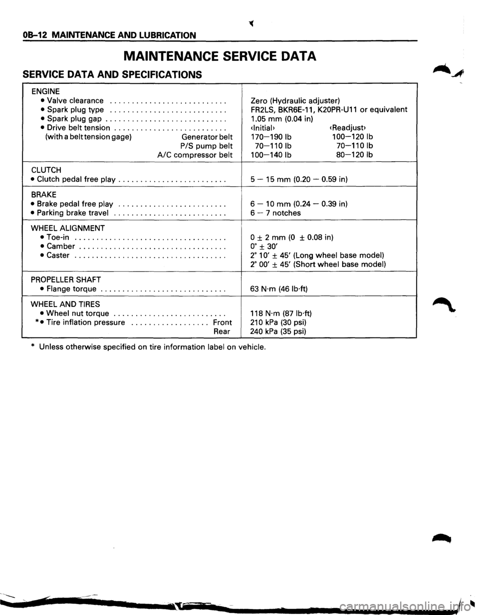
OB-12 MAINTENANCE AND LUBRICATION
MAINTENANCE SERVICE DATA
SERVICE DATA AND SPECIFICATIONS
ENGINE
• Valve clearance I o o I I I 0 0 0 I 0 o o o o o I 0 o o o 0 0 o o o o Zero (Hydraulic adjuster)
• Spark plug type I I o 0 I o 0 I I I 0 o o o I 0 I o o 0 0 0 o o 0 0 0 FR2LS, BKR6E-1 1, K20PR-U11 or equivalent
•
Spark plug gap ............................ 1.05 mm (0.04 in)
• Drive belt tension ..........................
(with a belttension gage)
Generator belt 170-190 lb 100-120 lb
PIS
pump belt 70-110 lb 70-110 lb
A/C compressor belt 100-140 lb 80-120 lb
CLUTCH
• Clutch pedal free play ......................... 5 -15 mm (0.20 -0.59 in)
BRAKE
• Brake pedal free play o o o o o o o o 0 0 o o o o o 0 0 o o 0 I o o o o 6 -10 mm (0.24 -0.39 in)
• Parking brake travel ••••••••••••••••••\
•• 0 ••••• 6-7 notches
WHEEL
ALIGNMENT
•
Toe-in 0 0 o o 0 0 I 0 0 o o o o 0 0 0 0 o o o o I 0 0 o o 0 0 o o o o 0 I 0 0 ± 2 mm (0 ± 0.08 in)
• Camber .................................. oo ± 30'
•
Caster o o o 0 0 0 0 o o o o o o I 0 0 o o o o 0 0 o o o o 0 o o o o o 0 0 o 2° 1 0' ± 45' (Long wheel base model)
2° 00' ± 45' (Short wheel base model)
PROPELLER SHAFT
• Flange torque ••••••••••••••••••\
•• 0' ••• 0 ••• 63 N·m (46 lb·ft)
WHEEL AND TIRES
• Wheel nut torque o o o o 0 0 o o o o o o o o o o o I o o o o 0 0 0 o 118 N·m (87 lb·ft)
* • Tire inflation pressure •••••••••••••• 0 ••• Front 21 0 kPa (30 psi)
Rear
240 kPa (35 psi)
* Unless otherwise specified on tire information label on vehicle.
~~-.... ¢ .............. .-I ~ -.,~iii~-..--. ....... 2 ........ -. .................. ~~ - I
Page 122 of 1928
3-2 DIAGNOSIS
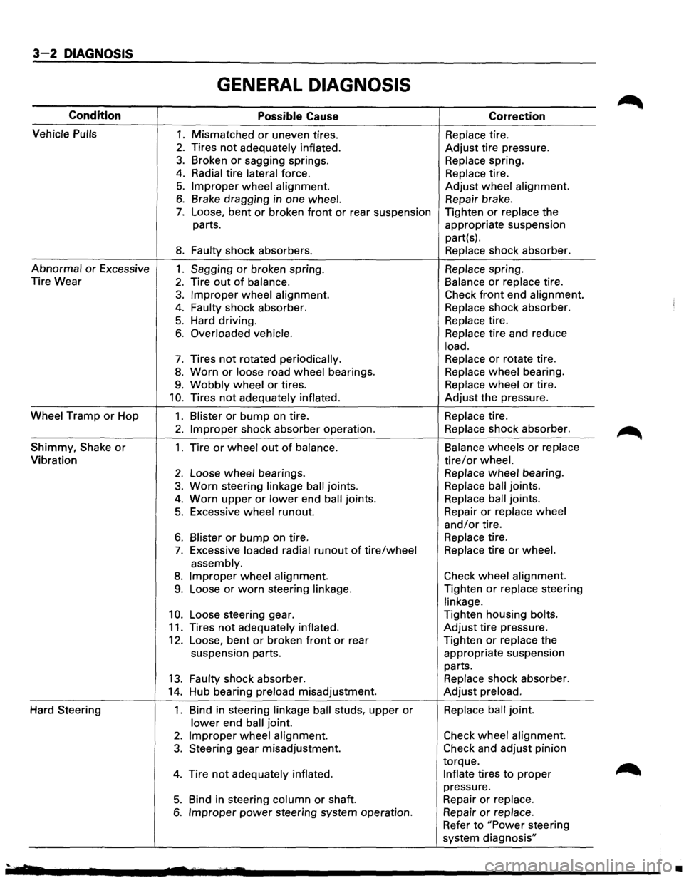
GENERAL DIAGNOSIS
Condition Possible Cause Correction
Vehicle
Pulls 1. Mismatched or uneven tires. Replace tire.
2. Tires not adequately inflated. Adjust tire pressure.
3. Broken or sagging springs. Replace spring.
4. Radial tire lateral force. Replace tire.
5. Improper wheel alignment. Adjust wheel alignment.
6. Brake dragging in one wheel. Repair brake.
7. Loose, bent or broken front or rear suspension Tighten or replace the
parts. appropriate suspension
part(s).
8. Faulty shock absorbers. Replace shock absorber.
Abnormal or Excessive 1. Sagging or broken spring. Replace spring.
Tire Wear
2. Tire out of balance. Balance or replace tire.
3. Improper wheel alignment. Check front end alignment.
4. Faulty shock absorber. Replace shock absorber.
5. Hard driving. Replace tire.
6. Overloaded vehicle. Replace tire
and reduce
load.
7. Tires not rotated periodically. Replace or rotate
tire.
8. Worn or loose road wheel bearings. Replace wheel bearing.
9. Wobbly wheel or tires. Replace wheel or tire.
10. Tires not adequately inflated. Adjust the pressure.
Wheel Tramp or Hop 1. Blister or bump on tire. Replace tire.
2. Improper shock absorber operation. Replace shock absorber.
Shimmy,
Shake or 1. Tire or wheel out of balance. Balance
wheels or replace
Vibration tire/or wheel.
2. Loose wheel bearings. Replace wheel bearing.
3. Worn steering linkage ball joints. Replace ball joints.
4. Worn upper or lower end ball joints. Replace ball joints.
5. Excessive wheel runout. Repair or replace
wheel
and/or tire.
6. Blister or bump on tire. Replace tire.
7. Excessive loaded radial runout of tire/wheel Replace tire or wheel.
assembly.
8. Improper wheel alignment. Check
wheel alignment.
9. Loose or worn steering linkage. Tighten or replace steering
linkage.
10. Loose steering gear. Tighten
housing bolts.
11. Tires not adequately inflated. Adjust tire pressure.
12. Loose, bent or broken front or rear Tighten or replace the
suspension parts. appropriate suspension
parts.
13. Faulty shock absorber. Replace shock absorber.
14. Hub bearing preload misadjustment. Adjust preload.
Hard Steering 1. Bind in steering linkage ball studs, upper or Replace ball joint.
lower end ball joint.
2. Improper wheel alignment. Check wheel alignment.
3. Steering gear misadjustment. Check and adjust pinion
torque.
4. Tire not adequately inflated. Inflate tires to proper
pressure.
5. Bind in steering column or shaft. Repair or replace.
6. Improper power steering
system operation. Repair or replace.
Refer to "Power steering
system diagnosis"
'· •
Page 123 of 1928
DIAGNOSIS 3-3
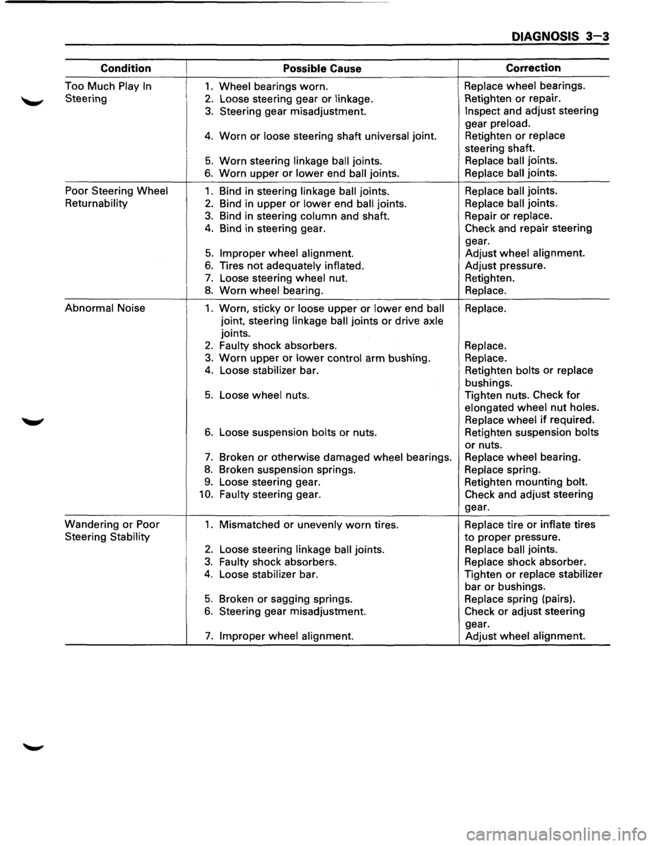
Condition Possible Cause Correction
Too
Much Play In 1. Wheel bearings worn. Replace wheel bearings.
Steering
2. Loose steering gear or linkage. Retighten or repair.
3. Steering
gear misadjustment. Inspect and adjust steering
gear preload.
4. Worn or loose steering shaft universal joint. Retighten or replace
steering shaft.
5. Worn steering linkage ball joints. Replace ball joints.
6. Worn upper or lower end ball joints. Replace ball joints.
Poor Steering
Wheel 1. Bind in steering linkage ball joints. Replace ball joints.
Returnability 2. Bind
in upper or lower end ball joints. Replace ball joints.
3. Bind
in steering column and shaft. Repair
or replace.
4. Bind in steering gear. Check and repair steering
gear.
5. Improper wheel alignment. Adjust wheel alignment.
6. Tires not adequately
inflated. Adjust
pressure.
7. Loose steering wheel nut. Retighten.
8. Worn wheel bearing.
Replace.
Abnormal Noise
1. Worn, sticky or loose upper or lower end ball Replace.
joint, steering linkage
ball joints or drive axle
joints.
2. Faulty shock absorbers.
Replace.
3. Worn upper or lower control arm bushing.
Replace.
4. Loose stabilizer bar. Retighten bolts or replace
bushings.
5. Loose wheel nuts. Tighten nuts. Check for
elongated wheel nut holes.
Replace
wheel if required.
6. Loose suspension bolts or nuts. Retighten suspension bolts
or nuts.
7. Broken or otherwise damaged wheel bearings. Replace wheel bearing.
8. Broken suspension springs. Replace spring.
9. Loose steering gear. Retighten mounting bolt.
10. Faulty steering gear. Check and adjust steering
gear.
Wandering
or Poor 1. Mismatched or unevenly worn tires. Replace tire or inflate tires
Steering
Stability to proper pressure.
2. Loose steering linkage ball joints. Replace ball joints.
3. Faulty shock absorbers. Replace shock absorber.
4. Loose stabilizer bar. Tighten or replace stabilizer
bar or bushings.
5. Broken or sagging springs. Replace spring (pairs).
6. Steering gear misadjustment. Check or adjust steering
gear.
7. Improper wheel alignment.
Adjust wheel alignment.
Page 124 of 1928
3-4 DIAGNOSIS
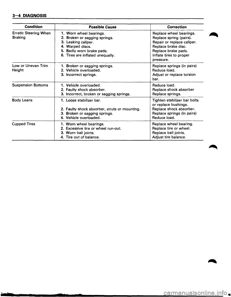
Condition Possible Cause Correction
Erratic Steering When 1. Worn wheel bearings. Replace wheel bearings.
Braking
2. Broken or sagging springs. Replace spring (pairs).
3. Leaking caliper. Repair or replace caliper.
4. Warped discs. Replace brake disc.
5. Badly worn brake pads. Replace brake pads.
6. Tires are inflated unequally. Inflate tires to proper
pressure.
Low or Uneven Trim
1. Broken or sagging springs. Replace springs (In pairs)
Height
2. Vehicle overloaded. Reduce load.
3. Incorrect springs. Adjust or replace torsion
bar.
Suspension Bottoms
1. Vehicle overloaded. Reduce load.
2. Faulty shock absorber. Replace shock absorber
3. Incorrect, broken or sagging springs. Replace springs.
Body Leans
1. Loose stabilizer bar. Tighten stabilizer bar bolts
or replace bushings.
2. Faulty shock
absorber, struts or mounting. Replace shock absorber.
3. Broken or sagging springs. Replace springs (In pairs)
4. Vehicle overloaded. Reduce load.
Cupped Tires 1. Worn wheel bearings. Replace wheel bearing.
2. Excessive tire or wheel run-out. Replace tire or wheel.
3. Worn ball joints. Replace ball joints.
4. Tire out of balance. Adjust tire balance.
•
Page 129 of 1928
DIAGNOSIS 3-9
TIRE DIAGNOSIS
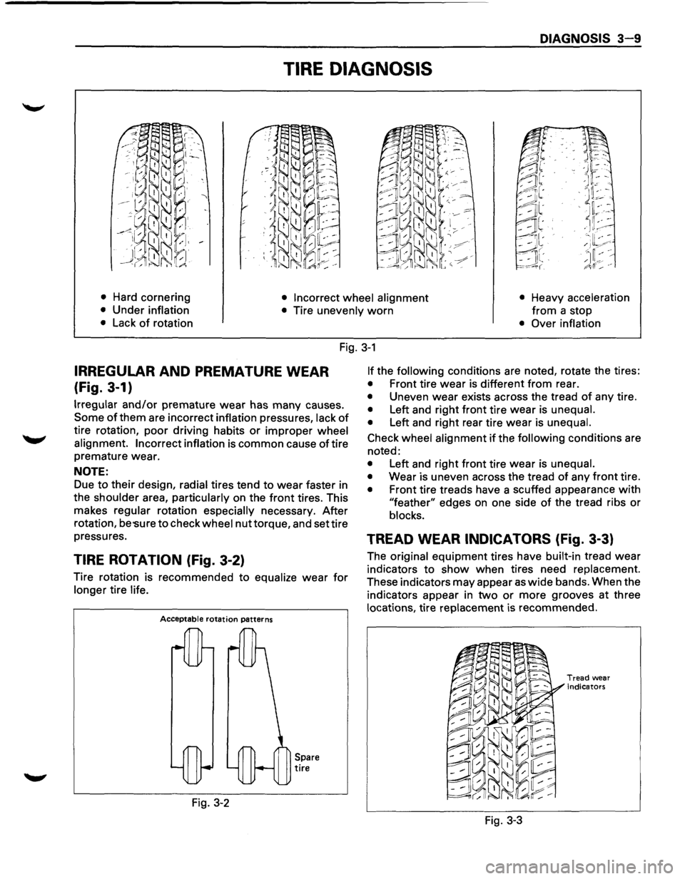
• Hard cornering • Incorrect wheel alignment • Heavy acceleration
from a
stop • Under inflation
• Tire unevenly worn
• Lack of rotation • Over inflation
Fig. 3-1
IRREGULAR AND PREMATURE WEAR
(Fig. 3-1)
Irregular and/or premature wear has many causes.
Some of them are incorrect inflation pressures, lack of
tire rotation, poor driving habits or improper wheel
alignment. Incorrect inflation
is common cause of tire
premature wear.
NOTE:
Due to their design, radial tires tend to wear faster in
the
shoulder area, particularly on the front tires. This
makes
regular rotation especially necessary. After
rotation,
be 'Sure to check wheel nut torque, and set tire
pressures.
TIRE ROTATION (Fig. 3-2)
Tire rotation is recommended to equalize wear for
longer tire life.
Acceptable rotation patterns
Fig. 3-2
Spare tire
If the following conditions are noted, rotate the tires:
• Front tire wear is different from rear.
• Uneven wear exists across the tread of any tire.
• Left and right front tire wear is unequal.
•
Left and right rear tire wear is unequal.
Check wheel alignment if the following conditions are
noted:
• Left and right front tire wear is unequal.
•
Wear is uneven across the tread of any front tire.
• Front tire treads have a scuffed appearance with
"feather" edges on one side of the tread ribs or
blocks.
TREAD WEAR INDICATORS (Fig. 3-3)
The original equipment tires have built-in tread wear
indicators to show when tires need replacement.
These indicators may appear as wide bands. When the
indicators appear in
two or more grooves at three
locations, tire replacement is recommended.
Fig. 3-3
Tread wear
indicators
Page 131 of 1928
DIAGNOSIS 3-11
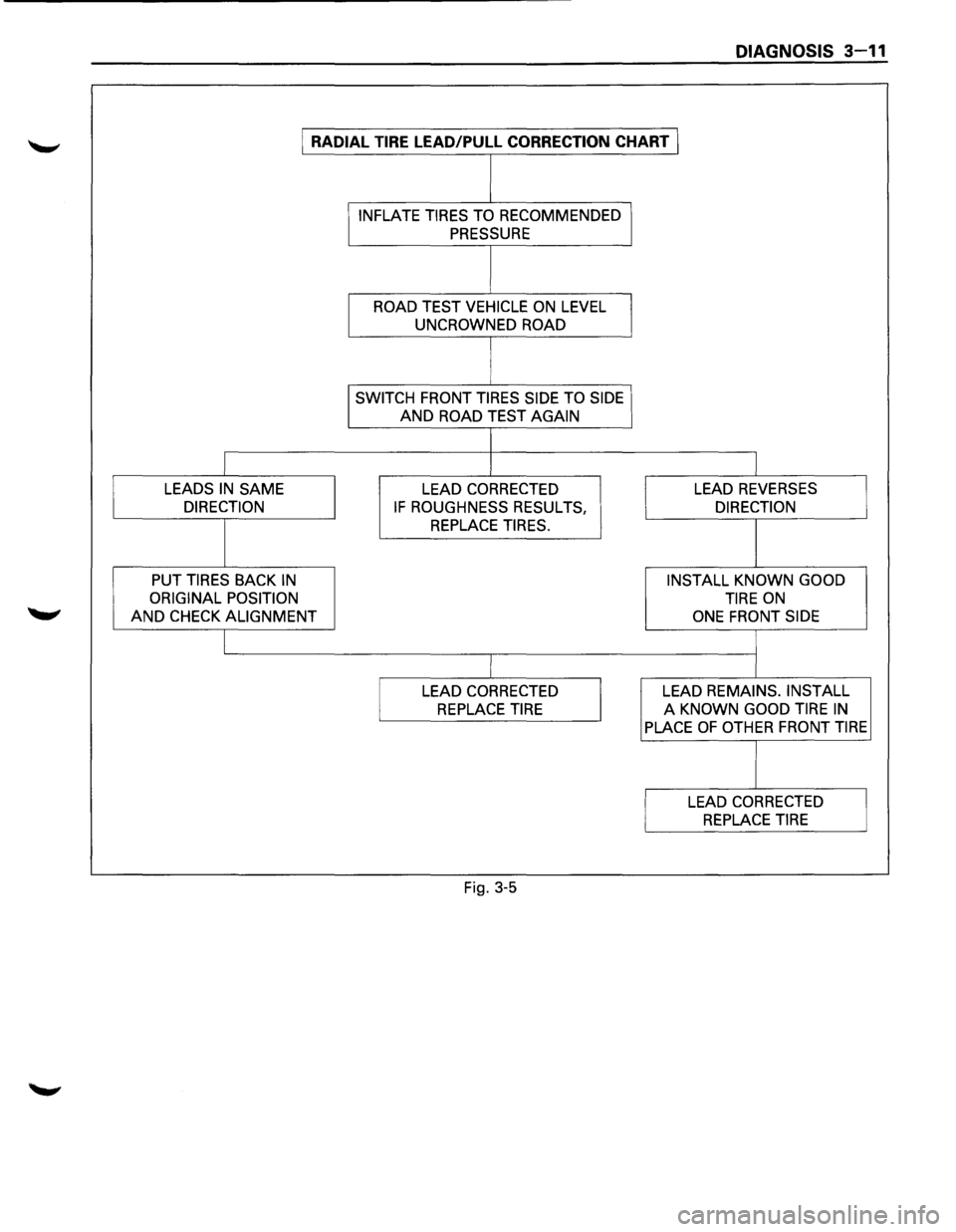
I RADIAL TIRE LEAD/PULL CORRECTION CHART I
I INFLATE TIRES TO RECOMMENDED I
PRESSURE
I
ROAD TEST VEHICLE ON LEVEL
I UNCROWNED ROAD
I SWITCH FRONT TIRES SIDE TO SIDE I
AND ROAD TEST AGAIN
LEADS IN
SAME LEAD CORRECTED LEAD REVERSES
DIRECTION
IF ROUGHNESS RESULTS, DIRECTION
REPLACE TIRES.
PUT TIRES
BACK IN INSTALL KNOWN GOOD
ORIGINAL POSITION
TIRE ON
AND CHECK ALIGNMENT ONE FRONT SIDE
LEAD CORRECTED LEAD REMAINS. INSTALL
REPLACE TIRE
A KNOWN GOOD TIRE IN
PLACE OF OTHER FRONT TIRE
LEAD CORRECTED
REPLACE TIRE
Fig. 3-5
Page 135 of 1928
FRONT END ALIGNMENT 3A-3
ON-VEHICLE SERVICE
INSPECTION
Before making any adjustments affecting caster,
camber or toe-in, the following front end inspection
should be made.
I L•IINSPECT
1. Tires for proper inflation pressure. Refer to
"Wheels and Tires" in section 3E.
2. Front wheel bearings for proper adjustment.
Refer to "Front Wheel Drive" in section 4C.
3. Ball joints, tie rod ends and relay rods. If
excessive looseness is noted, correct before
adjusting. Refer
to "Steering Linkage" in section
3B3.
4. Wheel and tires for run-out. Refer to "Wheels
and Tires" in section 3E.
5. Trim height. If not within specifications, the
correction
must be made before adjusting caster.
6. Steering gear for looseness at the frame.
7. Shock absorbers for leaks or any noticeable
noise.
Refer
to "Front Suspension" in section 3C.
8. Control arms or stabilizer bar attachment for
looseness. Refer to "Front Suspension" in section
3C.
9. Alignment equipment. Follow the manufacturer's
instructions.
10. Level of the vehicle. The vehicle must be on a
level surface.
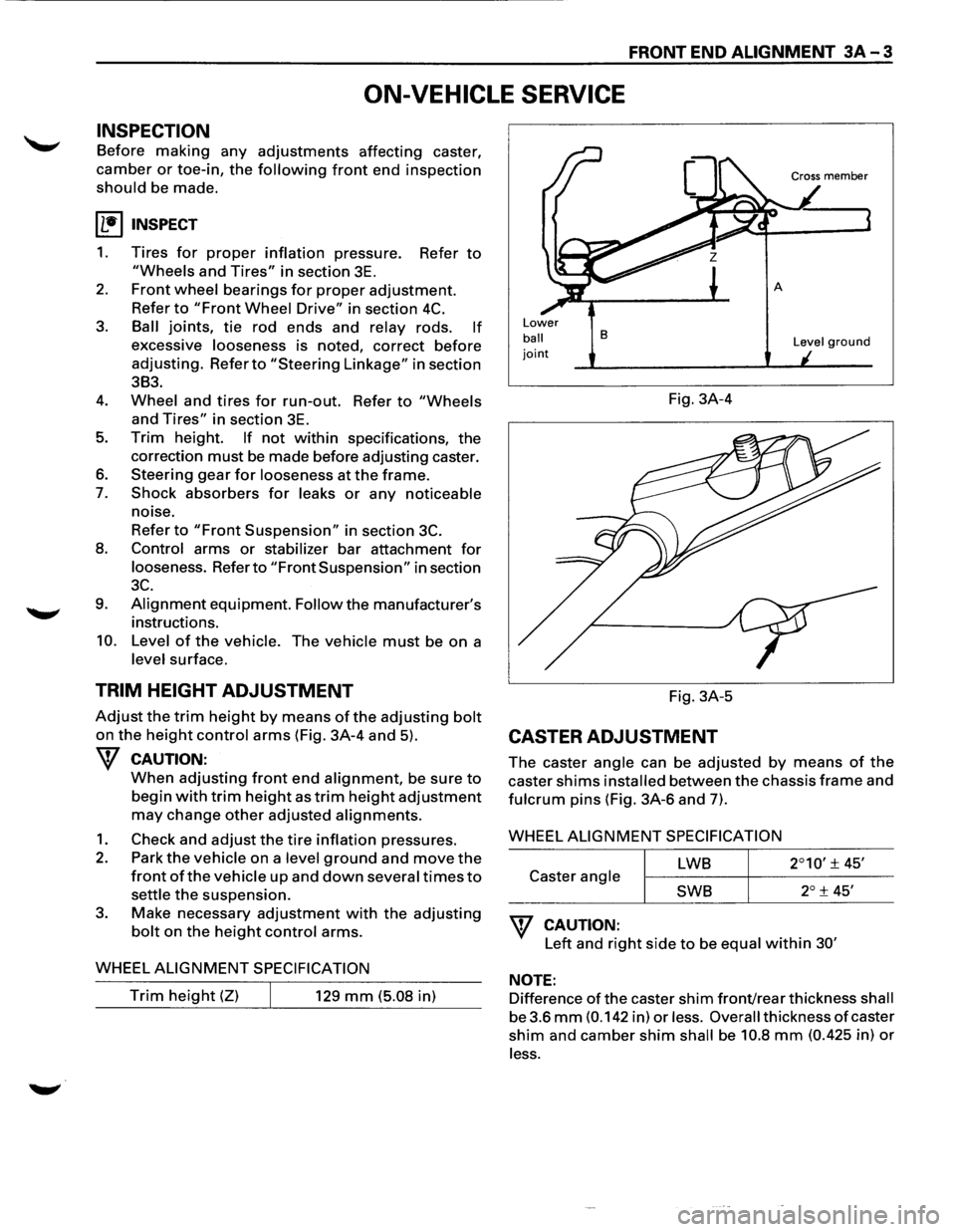
TRIM HEIGHT ADJUSTMENT
Adjust the trim height by means of the adjusting bolt
on the height control arms (Fig. 3A-4 and 5).
W CAUTION:
When adjusting front end alignment, be sure to
begin with trim height as trim height adjustment
may change other adjusted alignments.
1. Check and adjust the tire inflation pressures.
2. Park the vehicle on a level ground and move the
front of the vehicle up and down several times to
settle the suspension.
3. Make necessary adjustment with the adjusting
bolt on the height control arms.
WHEEL
ALIGNMENT SPECIFICATION
Trim height (Z) 129 mm (5.08 in)
Lower
ball joint
B
Fig. 3A-4
Fig. 3A-5
CASTER ADJUSTMENT
Level ground
The caster angle can be adjusted by means of the
caster shims installed between the chassis frame and
fulcrum pins (Fig. 3A-6 and 7).
WHEEL
ALIGNMENT SPECIFICATION
LWB
Caster angle
SWB
W CAUTION:
Left and right side to be equal within 30'
NOTE:
Difference of the caster shim front/rear thickness shall
be 3.6
mm (0.142 in) or less. Overall thickness of caster
shim and camber shim shall be 10.8 mm (0.425 in) or
less.
Page 201 of 1928
WHEELS AND TIRES 3E-1
SECTION 3E
WHEELS AND TIRES
W CAUTION:
When fasteners are removed, always reinstall them at the same location from which they were removed.
If a fastener needs to be replaced, use the correct part number fastener for that application. If the correct
part
number fastener is not available, a fastener of equal size and strength (or stronger) may be used.
Fasteners
that are not reused, and those requiring thread locking compound, will be called out. The correct
torque value must be used when installing fasteners that require it. If the above conditions are not
followed, parts or system damage could result.
CONTENTS
General Description . . . . . . . . . . . . . . . . . . . . . . . . . . . . . . . 3 E -1 Unit Repair .......................................... 3E-7
Diagnosis ........................................... 3E-2 Tires ............................................... 3E-7
Irregular and Premature Wear ................ 3E-2 Wheels ............................................ 3E-7
Inflation of Tires ................................. 3 E- 3 General Balance Procedure ................... 3E-8
Diagnosis List. . . . . . . . . . . . . . . . . . . . . . . . . . . . . . . . . . . . 3 E- 3 Balancing Wheel and Tire ...................... 3E-8
On-Vehicle Service ................................ 3E-6 Main Data and Specifications .................... 3E-9
Wheels ............................................ 3E-6 General Specifications ......................... 3E-9
Torque Specifications .......................... 3E-9
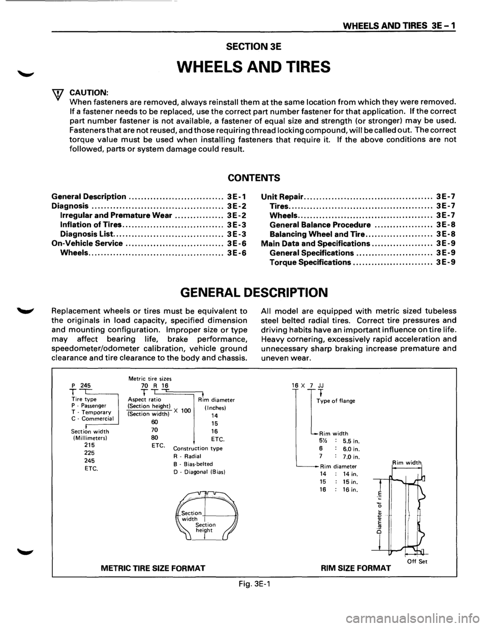
GENERAL DESCRIPTION
Replacement wheels or tires must be equivalent to
the originals in load capacity, specified dimension
and mounting configuration. Improper size or type
may affect bearing life, brake performance,
speedometer/odometer calibration, vehicle ground
clearance and tire clearance to the body and chassis.
p 245
T Tire type P -Passenger T -Temporary C -Commercial
Section
width (Millimeters) 215 225
245
ETC.
Metric tire sizes 70 R 16 T ,...
Aspect ratio I Rim diameter
(Section height)
(Section
width) X 100 (Inches)
14 60 70
80 ETC.
15
16 ETC.
Construction type
R-Radial
B - Bias-belted
D - Diagonal (Bias)
METRIC TIRE SIZE FORMAT
All model are equipped with metric sized tubeless
steel belted radial
tires. Correct tire pressures and
driving habits have an important influence on tire life.
Heavy cornering, excessively rapid acceleration and
unnecessary sharp braking increase
premature and
uneven wear.
16 X 7 JJ
I
~pe of flange
Rim width 5% 5.5 in.
6 6.0 in. 7 7.0 in.
Rim diameter Rim width
14 14 in. 15 15 in. 16 : 16 in.
I Off Set RIM SIZE FORMAT
Fig. 3E-1
Page 202 of 1928
3E-2 WHEELS AND TIRES
DIAGNOSIS
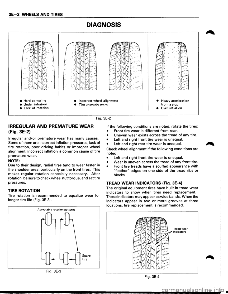
• Hard cornering • Incorrect wheel alignment
• Heavy acceleration from a stop • Under infration • Tire unevenly worn • Lack of rotation • Over inflation
Fig. 3E-2
IRREGULAR AND PREMATURE WEAR
(Fig. 3E-2)
Irregular and/or premature wear has many causes.
Some of them are incorrect inflation pressures, lack of
tire rotation, poor driving habits or improper wheel
alignment. Incorrect inflation
is common cause of tire
premature wear.
NOTE:
Due to their design, radial tires tend to wear faster in
the
shoulder area, particularly on the front tires. This
makes
regular rotation especially necessary. After
rotation, be sure to check wheel nut torque, and set tire
pressures.
TIRE ROTATION
Tire rotation is recommended to equalize wear for
longer tire life (Fig. 3E-3).
Acceptable rotation patterns
Fig. 3E-3
Spare tire
If the following conditions are noted, rotate the tires:
• Front tire wear is different from rear.
• Uneven wear exists across the tread of any tire.
• Left and right front tire wear is unequal.
•
Left and right rear tire wear is unequal.
Check wheel alignment if the following conditions are
noted:
• Left and right front tire wear is unequal.
•
Wear is uneven across the tread of any front tire.
• Front tire treads have a scuffed appearance with
"feather" edges on one side of the tread ribs or
blocks.
TREAD WEAR INDICATORS (fig. 3E-4)
The original equipment tires have built-in tread wear
indicators to show when tires need replacement.
These indicators may appear as wide bands. When the
indicators appear in
two or more grooves at three
locations, tire replacement is recommended.
Fig. 3E-4
Tread wear
indicators
•
Page 203 of 1928
INFLATION OF TIRES
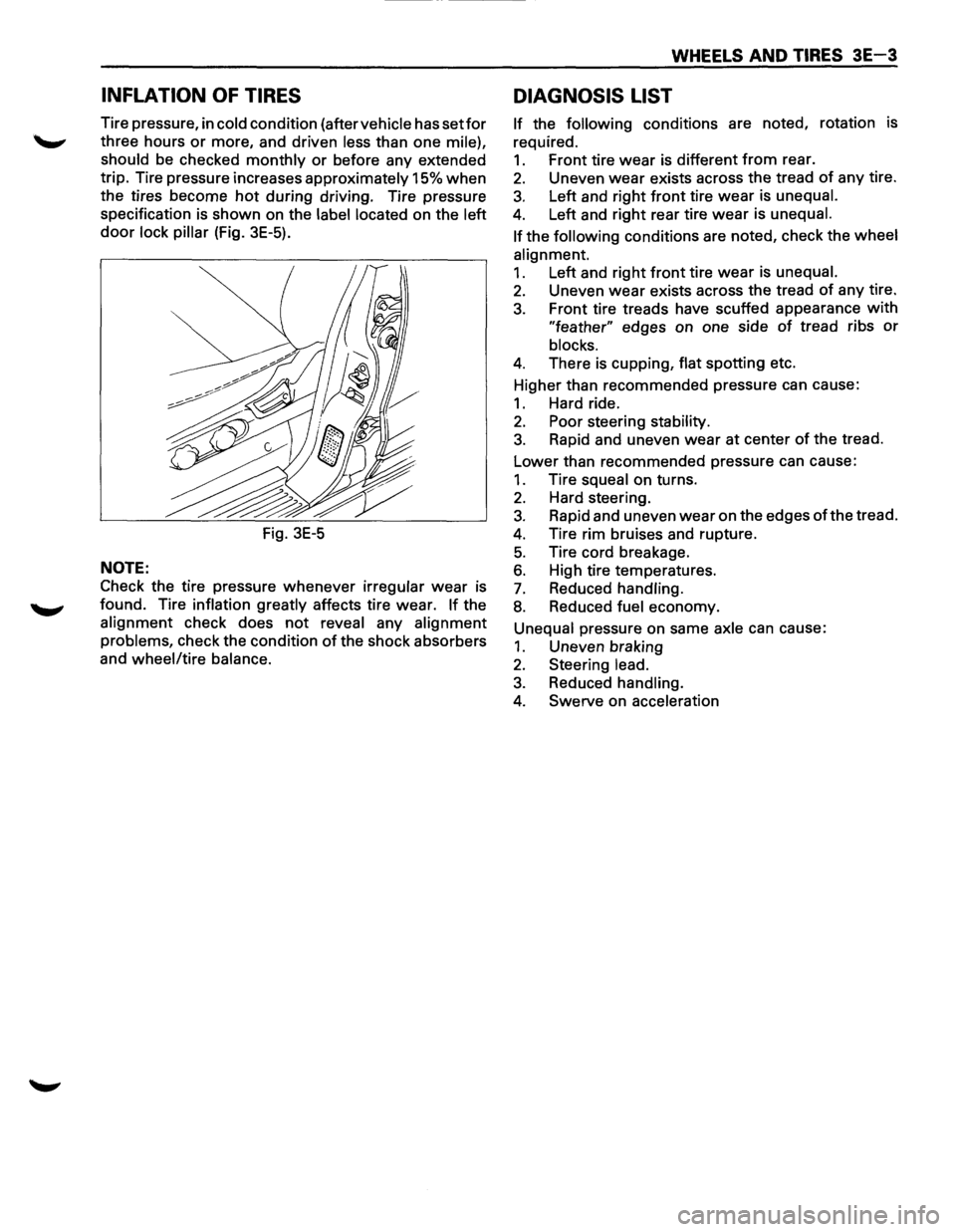
Tire pressure, in cold condition (after vehicle has setfor
three hours or more, and driven less than one mile),
should
be checked monthly or before any extended
trip. Tire pressure increases
approximately 15% when
the tires become hot during driving. Tire pressure
specification is shown on the
label located on the left
door lock pillar (Fig. 3E-5).
Fig.
3E-5
NOTE:
Check the tire pressure whenever irregular wear is
found. Tire
inflation greatly affects tire wear. If the
alignment check does not reveal any alignment
problems,
check the condition of the shock absorbers
and
wheel/tire balance.
WHEELS AND TIRES 3E-3
DIAGNOSIS LIST
If the following conditions are noted, rotation is
required.
1. Front tire wear is different from rear.
2. Uneven wear exists across the tread of any tire.
3. Left and right front tire wear is unequal.
4. Left and right rear tire wear is unequal.
If
the following conditions are noted, check the wheel
alignment.
1. Left and right front tire wear is unequal.
2. Uneven wear exists across the tread of any tire.
3. Front tire treads have scuffed appearance with
"feather" edges on one side of tread ribs or
blocks.
4. There is cupping, flat spotting etc.
Higher than recommended pressure can cause:
1. Hard ride.
2. Poor steering stability.
3. Rapid and uneven wear at center of the tread.
Lower than recommended pressure can cause:
1. Tire squeal on turns.
2. Hard steering.
3. Rapid and uneven wear on the edges of the tread.
4. Tire rim bruises and rupture.
5. Tire cord breakage.
6. High tire temperatures.
7. Reduced handling.
8. Reduced fuel economy.
Unequal pressure on same axle can cause:
1. Uneven braking
2. Steering lead.
3. Reduced handling.
4. Swerve on acceleration