flat tire ISUZU TROOPER 1995 Owner's Guide
[x] Cancel search | Manufacturer: ISUZU, Model Year: 1995, Model line: TROOPER, Model: ISUZU TROOPER 1995Pages: 1928
Page 1647 of 1928
15. Strip 13 mm(1/2 inch) of insulation from each wire
lead of the connector.
16.
Cut two 900 cm(30 feet) deployment wires from
0.8mm2(18 gauge) or thicker multi-strand wire.
These wires
will be used to fabricate the passenger
deployment harness.
17.
Strip 13 mm {1/2inch)of insulation from both ends of
the wires cut in the previous step.
18.
Short the wires by twisting together one end from
each.
Deployment wires shall remain shorted and
not be connected to a power source
until the air bag
is to be deployed.
WARNING: FAILURE TO FOLLOW
PROCEDURES
IN THE ORDER LISTED COULD RESULT IN
PERSONAL INJURY. NEVER CONNECT
DEPLOYMENT WIRES TO ANY POWER SOURCE
BEFORE CONNECTING DEPLOYMENT WIRES TO
THE INFLATOR MODULE LEADS. DEPLOYMENT
WIRES SHALL REMAIN SHORTED AND NOT BE
CONNECTED TO A POWER SOURCE UNTIL THE
AIR BAG IS DEPLOYED? THE INFLATOR MODULE
WILL IMMEDIATELY DEPLOY THE AIR BAG WHEN
A POWER
SOURCE IS CONNECTED TO IT. WEAR
SAFETY GLASSES THROUGHOUT THIS ENTIRE
DEPLOYMENT AND DISPOSAL PROCEDURE.
19. Twist
together one connector wire lead to one
deployment wire. The connection should be
mechanically secure.
20. Bend twisted connection made in the previous step
flat and wrap tightly with electrical tape to insulate
and secure.
21.
Twist together, bend and tape the remaining
connector wire lead to the remaining deployment
wire.
22. Connect the
deployment harness to the passenger
inflator module jumper, yellow 2-way connector
located behind the 1/P compartment door assembly.
Route deployment harness out the passenger side of
the
vehicle.
WARNING:
DEPLOYMENT WIRES SHALL REMAIN
SHORTED
AND NOT BE CONNECTED TO A POWER
SOURCE UNTIL THE AIR BAG IS TO BE DEPLOYED.
THE INFLATOR MODULE WILL IMMEDIATELY
DEPLOY THE AIR BAG WHEN A POWER SOURCE IS
CONNECTED TO IT. CONNECTING THE
DEPLOYMENT WIRES SHOULD ALWAYS BE THE
FINAL STEP IN THE INFLATOR MODULE
DEPLOYMENT PROCEDURE. FAILURE TO
FOLLOW PROCEDURES IN THE ORDER LISTED
COULD RESULT IN PERSONAL INJURY.
23. Verify that the inside of the vehicle and the area
surrounding the
vehicle are clear of all people and
loose or flammable objects.
24.
Stretch the driver and passenger deployment
harnesses to their full length.
Supplemental Restraint System 9J-23
. Completely cover windshield area and front door
window openings with a drop
cloth, blanket or similar
item. This reduced the possibility of injury due to
possible fragmentation of the vehicle's glass or
interior.
26. Notify
all people in the immediate area that you
intend to
deploy the air bags. The deployment will be
accompanied by a
loud noise which may startle the
uninformed.
27.
Separate the two ends of the driver deployment
harness wires.
WARNING: DEPLOYMENT WIRES SHALL REMAIN
SHORTED
AND NOT BE CONNECTED TO A POWER
SOURCE UNTIL THE AIR BAG IS TO BE DEPLOYED.
THE INFLATOR MODULE WILL IMMEDIATELY
DEPLOY THE AIR BAG WHEN A POWER SOURCE IS
CONNECTED TO IT. CONNECTING THE
DEPLOYMENT WIRES TO THE POWER SOURCE
SHOULD ALWAYS BE THE FINAL STEP IN THE
INFLATOR MODUL,E DEPLOYMENT PROCEDURE.
FAILURE TO FOLLOW PROCEDURES IN THE
ORDER LISTED COULD RESULT IN PERSONAL
INJURY.
NOTE: When the air bag deploys, the rapid gas
expansion will create a loud noise. Notify all people in the
immediate area that you intend to
deploy the air bags.
28. Connect the driver
deployment harness wires to a
power source to immediately deploy the driver
inflator module. Recommended application: 12 volts
minimum, 2 amps minimum. A vehicle battery is
suggested.
29.
Separate the two ends of the passenger deployment
harness wires.
WARNING: DEPLOYMENT WIRES SHALL REMAIN
SHORTED
AND NOT BE CONNECTED TO A POWER
SOURCE UNTIL THE AIR BAG IS TO BE DEPLOYED.
THE INFLATOR MODULE WILL IMMEDIATELY
DEPLOY THE AIR BAG WHEN A POWER SOURCE IS
CONNECTED TO IT. CONNECTING THE
DEPLOYMENT WIRES TO THE POWER SOURCE
SHOULD ALWAYS BE THE FINAL STEP IN THE
INFLATOR MODULE DEPLOYMENT PROCEDURE.
FAILURE TO FOLLOW PROCEDURES IN THE
ORDER LISTED COULD RESULT IN PERSONAL
INJURY.
30.
Connectthe passenger deployment harness wires to
a power source to
immediately deploy the passenger
inflator module. Recommended application: 12 volts
minimum, 2 amps minimum. A vehicle battery is
suggested.
After
an inflator module has been deployed, the
surface of the air bag may contain a powdery
residue. This powder consists primarily of cornstarch
(used to lubricate the bag as it inflates) and
byproducts of the chemical reaction. Sodium
hydroxide dust (similar to lye soap) is produced as a
byproduct of the
deployment reaction. The sodium
Page 1648 of 1928
9J-24 Supplemental Restraint System
hy~roxide th~n quickly reacts with atmospheriC' PROCEDURES COULD RESULT IN PERSONAL
mo1sture and IS converted to sodium carbonate and INJURY.
so~ium bicarbonate (baking soda). Therefore, it is
unlikely that sodium hydroxide will be present after
deployment.
As a precaution, however, gloves and
safety glasses are recommended to prevent any
possible irritation of the skin or eyes.
WARNING: SAFETY PRECAUTIONS MUST BE
OBSERVED WHEN HANDLING A DEPLOYED
INFLATOR MODULE. AFTER DEPLOYMENT, THE
METAL
SURFACES OF THE INFLATOR MODULE
WILL BE VERY HOT. ALLOW THE INFLATOR
MODULE TO COOL BEFORE HANDLING ANY
METAL PORTION OF IT. DO NOT PLACE THE HOT
DEPLOYED INFLATOR MODULE NEAR ANY
FLAMMABLE OBJECTS. FAILURE TO FOLLOW
PROCEDURES COULD RESULT IN FIRE OR
PERSONAL INJURY.
After an inflator module has been deployed, the metal
canister and surrounding areas of the inflator module will
be very hot. Do not touch the metal areas of the inflator
module for about
10 minutes after deployment. If the
deployed inflator module must be moved before it
is cool,
wear gloves
and handle by the air bag or vinyl trim.
31. S~o~t the driver deployment harness wires by
tw1st1ng together one end from each. Repeat this
procedure for the passenger deployment harness.
32. Carefully remove drop cloth from vehicle and clean
off any fragments or discard drop cloth entirely.
33. Disconnect driver deployment harness and
passenger deployment harness from vehicle and
discard.
34.
In the unlikely event that either or both of the inflator
modules did not deploy after following these
procedures, proceed immediately with Steps 36
through
38. If the inflator module deployed proceed
step
35.
35. With both air bags deployed, the vehicle may be
scrapped in the same manner as a non-SRS
equipped vehicle.
NOTE: The remaining steps are to be followed in the
unlikely event that the inflator module did not deploy otter
following these procedures.
36. Remove the undeployed inflator module(s) from the
vehicle. For driver inflator module refer to
in this
section for passenger inflator module
"On-Vehicle
Service".
WARNING:
WHEN STORING A LIVE INFLATOR
MODULE OR WHEN LEAVING A LIVE INFLATOR
MODULE
UNATTENDED ON A BENCH OR OTHER
SURFACE, ALWAYS FACE THE BAG AND TRIM
COVER
UP, AWAY FROM THE SURFACE. THIS IS
NECESSARY SO THAT A FREE SPACE IS
PROVIDED
TO ALLOW THE AIR BAG TO EXPAND IN
THE UNLIKELY EVENT OF ACCIDENTAL
DEPLOYMENT. FAILURE TO FOLLOW
37. Temporarily store the inflator module with the air bag
opening facing
up, away from the surface upon which
it rests.
38. Call the Technical Assistance group for further
assistance.
DEPLOYED INFLATOR MODULE HANDLING
After the inflator module has been deployed, the surface
of the air bag may contain a powdery residue. This
powder
consists primarily of cornstarch (used to
lubricate the bag as it inflates) and byproducts of the
chemical reaction.
Sodium hydroxide dust (similar to lye
soap)
is produced as a byproduct of the deployment
reaction. The sodium hydroxide then quickly reacts with
atmospheric moisture and is converted
to sodium
carbonate and sodium bicarbonate (baking soda}.
Therefore, it
is unlikely that sodium hydroxide will be
present after deployment. As with many service
procedures, you should wear gloves and safety glasses.
Page 1749 of 1928
Supplemental Restraint System 9J-125
STEERING WHEEL
WARNING: SAFETY PRECAUTIONS MUST BE FOLLOWED WHEN HANDLING A DEPLOYED INFLATOR
MODULE(AIR BAG). AFTER DEPLOYMENT, THE INFLATOR MODULE(AIR BAG) SURFACE MAY CONTAIN A
SMALL AMOUNT OF SODIUM HYDROXIDE, A BY-PRODUCT OF THE DEPLOYMENT REACTION, THAT IS
IRRITATING TO
THE SKIN AND EYES. MOST OF THE POWDER ON THE INFLATOR MODULE (AIR BAG )IS
HARMLESS.
AS A PRECAUTION, WEAR GLOVES AND SAFETY GLASSES WHEN HANDLING A DEPLOYED
INFLATOR MODULE (AIR BAG ), AND WASH YOUR HANDS WITH MILD SOAP AND WATER AFTERWARDS.
WARNING: WHEN CARRYING A LIVE INFLATOR MODULE (AIR BAG ), MAKE SURE THE BAG AND TRIM
COVER
ARE POINTED AWAY FROM YOU. NEVER CARRY INFLATOR MODULE (AIR BAG )BY THE WIRES OR
CONNECTOR ON
THE UNDERSIDE OF MODULE. IN THE CASE OF AN ACCIDENTAL DEPLOYMENT, THE BAG
WILL THEN DEPLOY WITH MINIMAL CHANCE OF INJURY. WHEN PLACING A LIVE INFLATOR MODULE (AIR
BAG ) ON A BENCH OR OTHER SURFACE, ALWAYS FACE BAG AND TRIM COVER UP, AWAY FROM THE
SURFACE.NEVER
REST A STEERING COLUMN ASSEMBLY ON THE STEERING WHEEL WITH THE INFLATOR
MODULE (AIR BAG ) FACE DOWN AND COLUMN VERTICAL. THIS IS NECESSARY SO THAT A FREE SPACE
IS PROVIDED
TO ALLOW THE INFLATOR MODULE (AIR BAG) TO EXPAND IN THE UNLIKELY EVENT OF
ACCIDENTAL DEPLOYMENT. OTHERWISE, PERSONAL INJURY COULD RESULT.
NOTE: In
the event deployment has occurred, inspect coil assembly wire for any signs of scorching, melting or any
other damage due to excessive heat.
If the coil has been damaged, replace it.
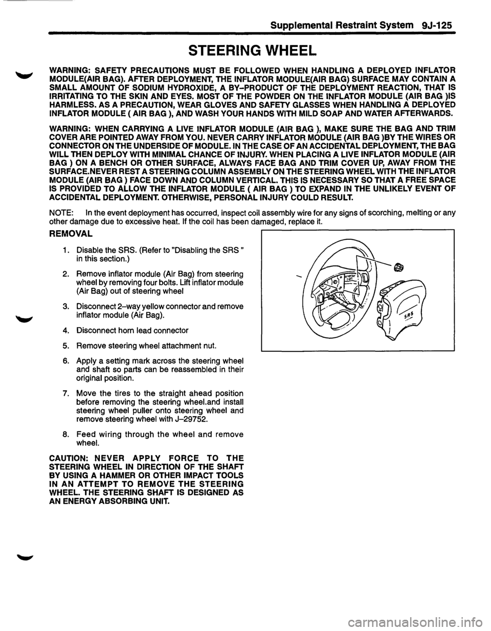
REMOVAL ~-----------------------------,
1. Disable the SRS. (Refer to "Disabling the SRS "
in this section.)
2. Remove
inflator module (Air Bag) from steering
wheel by removing four bolts. Lift inflator module
(Air Bag) out of steering wheel
3. Disconnect 2-way yellow connector and remove
inflator module (Air Bag).
4. Disconnect horn lead connector
5. Remove steering wheel attachment nut.
6. Apply a setting mark across the steering wheel
and shaft so parts can be reassembled in their
original position.
7.
Move the tires to the straight ahead position
before removing the steering
wheel.and install
steering wheel puller onto steering wheel and
remove steering
wheel with J-29752.
8. Feed wiring through the wheel and remove
wheel.
CAUTION:
NEVER APPLY FORCE TO THE
STEERING WHEEL IN DIRECTION OF THE SHAFT
BY USING A HAMMER OR OTHER IMPACT TOOLS
IN AN ATTEMPT TO REMOVE THE STEERING
WHEEL. THE STEERING SHAFT IS DESIGNED AS
AN ENERGY ABSORBING UNIT.
-
Page 1751 of 1928
Supplemental Restraint System 9J-127
SRS COIL ASSEMBLY
WARNING: SAFETY PRECAUTIONS MUST BE FOLLOWED WHEN HANDLING A DEPLOYED INFLATOR
MODULE{AIR
BAG). AFTER DEPLOYMENT, THE INFLATOR MODULE{AIR BAG) SURFACE MAY CONTAIN A
SMALL AMOUNT OF SODIUM HYDROXIDE, A BY-PRODUCT OF THE DEPLOYMENT REACTION, THAT IS
IRRITATING TO
THE SKIN AND EYES. MOST OF THE POWDER ON THE INFLATOR MODULE (AIR BAG )IS
HARMLESS.
AS A PRECAUTION, WEAR GLOVES AND SAFETY GLASSES WHEN HANDLING A DEPLOYED
INFLATOR MODULE {AIR BAG ), AND WASH YOUR HANDS WITH MILD SOAP AND WATER AFTERWARDS.
WARNING: WHEN CARRYING A LIVE INFLATOR MODULE {AIR BAG ), MAKE SURE THE BAG AND TRIM
COVER
ARE POINTED AWAY FROM YOU. NEVER CARRY INFLATOR MODULE {AIR BAG )BY THE WIRES OR
CONNECTOR ON
THE UNDERSIDE OF MODULE. IN THE CASE OF AN ACCIDENTAL DEPLOYMENT, THE BAG
WILL THEN DEPLOY WITH MINIMAL CHANCE OF INJURY. WHEN PLACING A LIVE INFLATOR MODULE (AIR
BAG ) ON A BENCH OR OTHER SURFACE, ALWAYS FACE BAG AND TRIM COVER UP, AWAY FROM THE
SURFACE. NEVER REST A STEERING COLUMN ASSEMBLY ON THE STEERING WHEEL WITH THE INFLATOR
MODULE (AIR BAG) FACE DOWN AND COLUMN VERTICAL. THIS IS NECESSARY SO THAT A FREE SPACE
IS PROVIDED TO
ALLOW THE INFLATOR MODULE { AIR BAG ) TO EXPAND IN THE UNLIKELY EVENT OF
ACCIDENTAL
DEPLOYMENT. OTHERWISE, PERSONAL INJURY COULD RESULT.
NOTE:
In the event deployment has occurred, inspect coil assembly wire for any signs of scorching, melting or any
other damage due to excessive heat.
If the coil has been damaged, replace it.
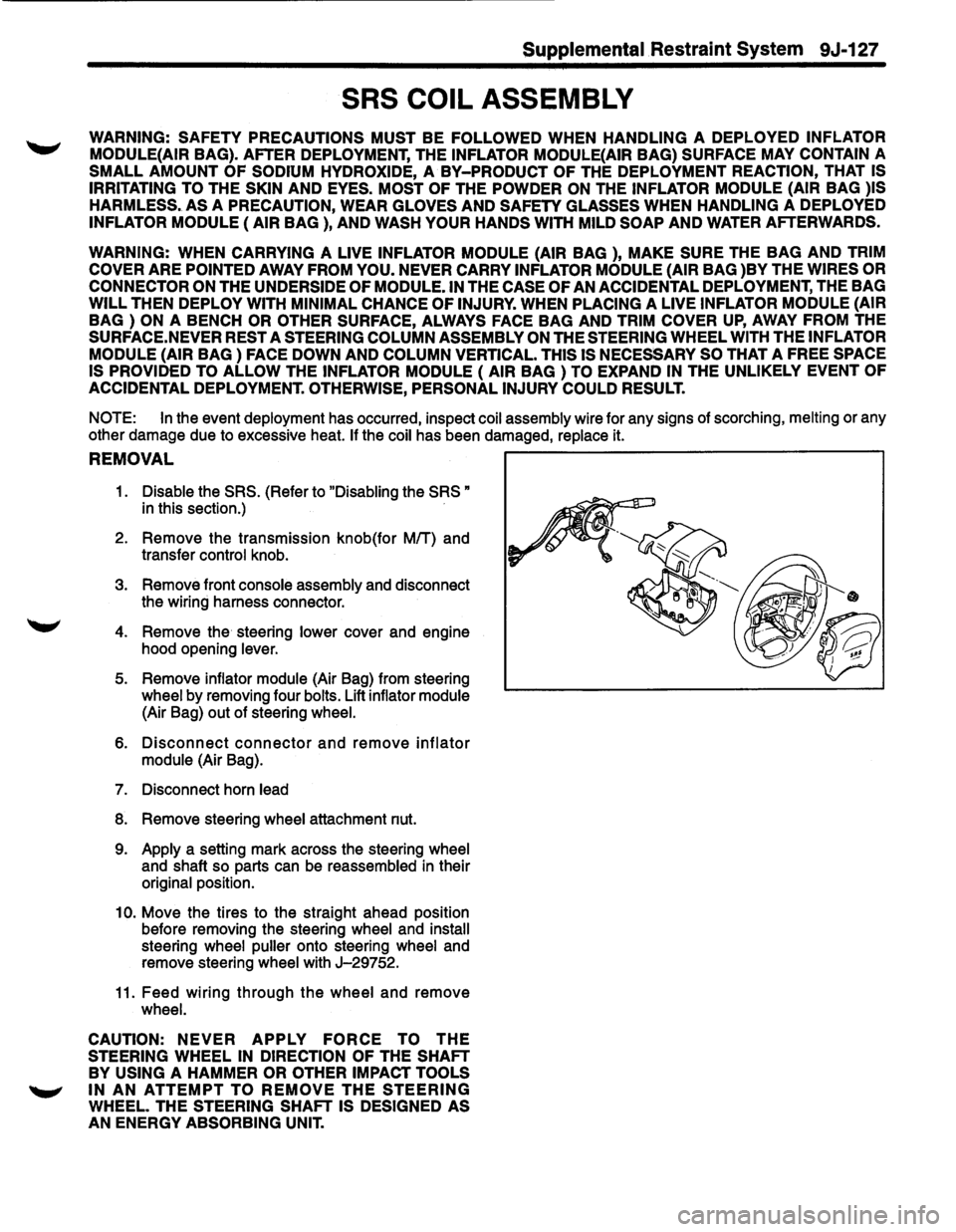
REMOVAL ~------------------------------------------,
1. Disable the SRS. (Refer to "Disabling the SRS"
in this section.)
2. Remove the transmission knob(for
MIT) and
transfer
control knob.
3. Remove front console assembly and disconnect
the wiring harness connector.
4. Remove the steering lower cover and engine
hood opening
lever.
5. Remove inflator module (Air Bag) from steering
wheel by removing four bolts. Lift inflator module
(Air Bag) out of steering wheel.
6. Disconnect connector and remove inflator
module (Air Bag).
7. Disconnect horn lead
8. Remove steering wheel attachment nut.
9. Apply a setting mark across the steering wheel
and shaft so parts can be reassembled in their
original position.
10. Move the tires to the straight ahead position
before removing the steering
wheel and install
steering wheel puller onto steering wheel and
remove steering
wheel with J-29752.
11. Feed wiring through the wheel and remove
wheel.
CAUTION:
NEVER APPLY FORCE TO THE
STEERING WHEEL IN DIRECTION OF THE SHAFT
BY USING A HAMMER OR OTHER IMPACT TOOLS
~ IN AN ATTEMPT TO REMOVE THE STEERING
WHEEL. THE STEERING SHAFT IS DESIGNED AS
AN ENERGY ABSORBING UNIT.
Page 1753 of 1928
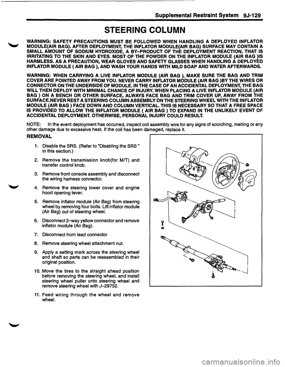
Supplemental Restraint System 9J-129
STEERING COLUMN
WARNING: SAFETY PRECAUTIONS MUST BE FOLLOWED WHEN HANDLING A DEPLOYED INFLATOR
MODULE{AIR
BAG). AFTER DEPLOYMENT, THE INFLATOR MODULE{AIR BAG) SURFACE MAY CONTAIN A
SMALL AMOUNT OF SODIUM HYDROXIDE, A BY-PRODUCT OF THE DEPLOYMENT REACTION, THAT IS
IRRITATING TO
THE SKIN AND EYES. MOST OF THE POWDER ON THE INFLATOR MODULE (AIR BAG )IS
HARMLESS.
AS A PRECAUTION, WEAR GLOVES AND SAFETY GLASSES WHEN HANDLING A DEPLOYED
INFLATOR MODULE (AIR BAG ), AND WASH YOUR HANDS WITH MILD SOAP AND WATER AFTERWARDS.
WARNING: WHEN CARRYING A LIVE INFLATOR MODULE {AIR BAG ), MAKE SURE THE BAG AND TRIM
COVER
ARE POINTED AWAY FROM YOU. NEVER CARRY INFLATOR MODULE (AIR BAG )BY THE WIRES OR
CONNECTOR ON
THE UNDERSIDE OF MODULE. IN THE CASE OF AN ACCIDENTAL DEPLOYMENT, THE BAG
WILL THEN DEPLOY WITH MINIMAL CHANCE OF INJURY. WHEN PLACING A LIVE INFLATOR MODULE (AIR
BAG ) ON A BENCH OR OTHER SURFACE, ALWAYS FACE BAG AND TRIM COVER UP, AWAY FROM THE
SURFACE.NEVER REST A STEERING COLUMN ASSEMBLY ON THE STEERING WHEEL WITH THE INFLATOR
MODULE {AIR
BAG) FACE DOWN AND COLUMN VERTICAL. THIS IS NECESSARY SO THAT A FREE SPACE
IS PROVIDED TO
ALLOW THE INFLATOR MODULE (AIR BAG) TO EXPAND IN THE UNLIKELY EVENT OF
ACCIDENTAL
DEPLOYMENT. OTHERWISE, PERSONAL INJURY COULD RESULT.
NOTE:
In the event deployment has occurred, inspect coil assembly wire for any signs of scorching, melting or any
other damage due to excessive heat.
If the coil has been damaged, replace it.
REMOVAL ~--------------------------~
1. Disable the SRS. (Refer to "Disabling the SRS "
in this section.)
2. Remove the transmission knob(for MIT) and
transfer
control knob.
3. Remove front console assembly and disconnect
the wiring harness connector.
4. Remove the steering lower cover and engine
hood opening
lever.
5. Remove inflator module (Air Bag) from steering
wheel by removing four bolts. Lift inflator module
(Air Bag) out of steering wheel.
6. Disconnect 2-way yellow connector and remove
inflator module (Air Bag).
7. Disconnect horn lead connector
8. Remove steering wheel attachment nut.
9. Apply a setting mark across the steering wheel
and shaft so parts can be reassembled in their
original position.
1
0. Move the tires to the straight ahead position
before removing the steering
wheel, and install
steering wheel puller onto steering wheel and
remove steering
wheel with J-29752.
11. Feed wiring through the wheel and remove
wheel.
y
®