key battery ISUZU TROOPER 1995 Owner's Manual
[x] Cancel search | Manufacturer: ISUZU, Model Year: 1995, Model line: TROOPER, Model: ISUZU TROOPER 1995Pages: 1928
Page 931 of 1928
AUTOMATIC TRANSMISSION (4l30-E) 7A-59
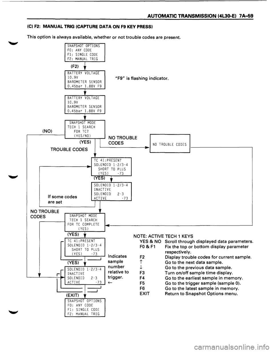
(C) F2: MANUAL TRIG (CAPTURE DATA ON F9 KEY PRESS)
This option is always available, whether or not trouble codes are present.
SNAPSHOT OPTIONS FO: ANY CODE Fl: SINGLE CODE F2: MANUAL TRIG
(F2)
BATTERY VOLTAGE
10.9V BAROMETER SENSOR 0.45bar 1.88V F9
"F9" is flashing indicator.
'
BATTERY VOLTAGE 10.9V BAROMETER SENSOR 0.45bar 1.88V F9
j_
SNAPSHOT MODE TECH 1 SEARCH (NO) FOR TC?
CYES/NOl
(YES)
TROUBLE CODES
NO TROUBLE
CODES
TC 41:PRESENT
.----------~· SOLENOID 1-2/3-4 SHORT TO PLUS
CYESl -73
(YES) y
SOLENOID 1-2/3-4
INACTIVE
If some codes
are set SOLENOID 2-3 ACTIVE -73
NO TROUBLE
CODES SNAPSHOT MODE
TECH 1 SEARCH FOR TC COMPLETE CYESl
NO TROUBLE CODES ..
(YES) j NOTE: ACTIVE TECH 1 KEYS r-TC 41: PRESENT SOLENOID 1-2/3-4
SHORT TO PLUS CYESl -73 I Indicates
(YES)
sample
r--~~:--":'"~~ number
r[ i~~g~0~ 1 -2
/3
-4 relative
to
'---...L----=--
1
~ soLEN~ I-D r-------l-2 _-~...;.7.;;..3 1
__, ~gger.
(EXIT)
SNAPSHOT OPTIONS FO: ANY CODE Fl: SINGLE CODE F2: MANUAL TRIG
YES & NO Scroll through displayed data parameters.
FO & F1 Fix the top or bottom display parameter
F2
I
J,
F3
F4
F5
F6
EXIT
respectively.
Display trouble codes for current sample.
Go to the next data sample.
Go to the previous data sample.
Turn
on/off sample time display.
Go to the earliest sample in memory.
Go to the trigger sample (sample 0).
Go to the latest sample in memory.
Return to Snapshot Options menu.
Page 1029 of 1928
Rubber band
Fig. 7A-16c
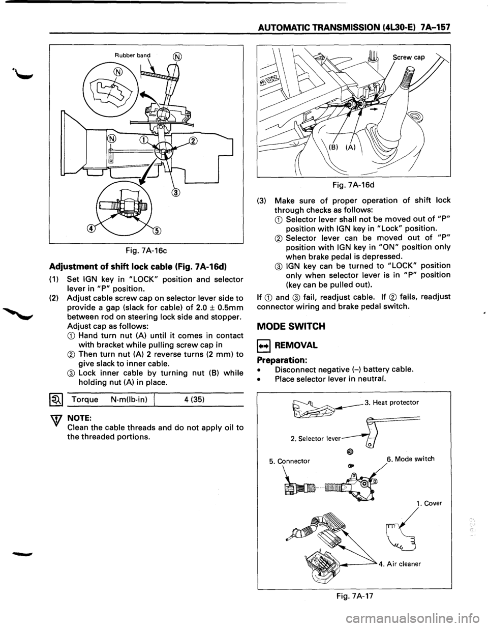
Adjustment of shift lock cable (Fig. 7A-16d)
(1) Set IGN key in "LOCK" position and selector
lever
in "P" position.
(2)
Adjust cable screw cap on selector lever side to
provide a gap (slack for cable) of 2.0 ± O.Smm
between rod on steering lock side and stopper.
Adjust cap as follows:
CD Hand turn nut (A) until it comes in contact
with bracket while pulling screw cap in
® Then turn nut (A) 2 reverse turns (2 mm) to
give slack to inner cable.
@ Lock inner cable by turning nut (8) while
holding nut (A) in place.
~~~ Torque N-m(lb-in) j 4 (35)
W NOTE:
Clean the cable threads and do not apply oil to
the threaded portions.
AUTOMATIC TRANSMISSION (4L30·E) 7A-157
Fig. 7A-16d
(3) Make sure of proper operation of shift lock
through checks as follows:
CD Selector lever shall not be moved out of "P"
position with IGN key in "Lock" position.
® Selector lever can be moved out of "P"
position with IGN key in "ON" position only
when brake pedal is depressed.
@ IGN key can be turned to "LOCK" position
only when selector lever is in "P" position
(key can be
pulled out).
If CD and @ fail, readjust cable. If ® fails, readjust
connector
wiring and brake pedal switch.
MODE SWITCH
1++1 REMOVAL
Preparation:
• Disconnect negative (-) battery cable.
• Place selector lever
in neutral.
~3. Heat protector
2. Selector lever
6. Mode switch
1. Cover
~
Fig. 7A-17
Page 1326 of 1928
8 -136 CHASSIS ELECTRICAL
MAP LIGHT SWITCH/BULB
~ INSPECTION
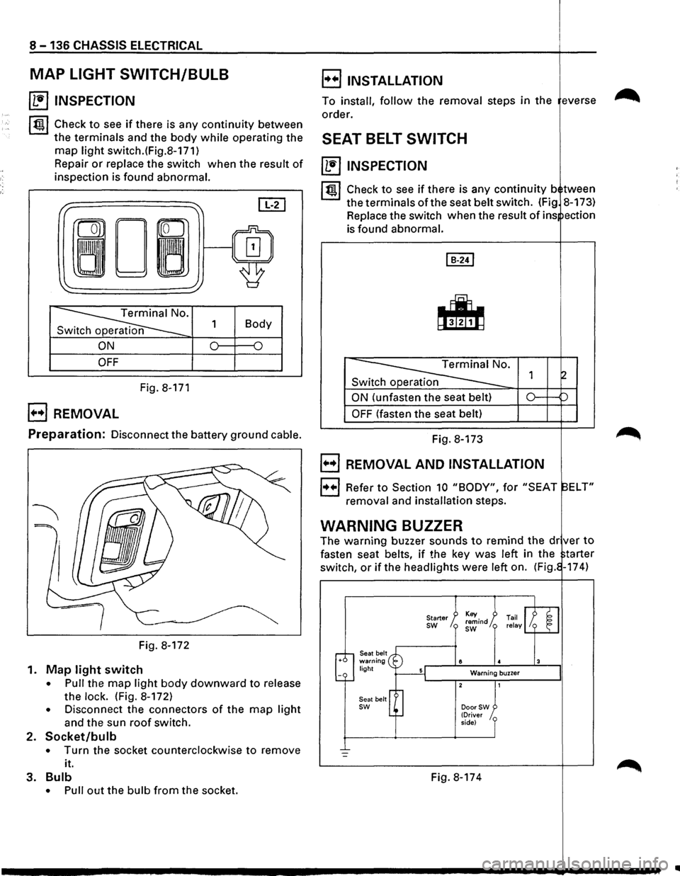
~~~ Check to see if there is any continuity between
the terminals and the body while operating the
map light switch.(Fig.8-171)
Repair
or replace the switch when the result of
inspection is found abnormal.
I" ~ [IT]
ron
0~/~ ~
'
~· 1 Body
n
ON 0 {)
OFF
Fig. 8-171
B REMOVAL
E) INSTALLATION
To install, follow the removal steps in the everse
order.
SEAT BELT SWITCH
~ INSPECTION
I~ l Check to see if there is any continuity b tween
the terminals of the seat belt switch. (Fig 8-173)
Replace the switch when the
result of ins ection
is found abnormal.
Switch operation
ON (unfasten the seat belt)
OFF (fasten the seat belt)
Preparation: Disconnect the battery ground cable. Fig. 8-173
Fig. 8-172
1.
Map light switch
• Pull the map light body downward to release
the
lock. (Fig. 8-172)
• Disconnect the connectors of the map light
and the sun roof switch.
2. Socket/bulb
• Turn the socket counterclockwise to remove
it.
3.
Bulb
• Pull out the bulb from the socket.
B REMOVAL AND INSTALLATION
1++1 Refer to Section 10 "BODY", for "SEAT ELT"
removal and installation steps.
WARNING BUZZER
The warning buzzer sounds to remind the dr ver to
fasten seat belts, if the key was left in the tarter
switch,
or if the headlights were left on. (Fig. -174)
Seat belt warning light
Seat belt
sw
Starter sw
8
Warning buzzer
DoorSW (Driver
side)
Fig. 8-174
..
Page 1329 of 1928
B REMOVAL (FIG. 8-176)
Preparation: Disconnect the battery ground cable.
1. Dash side trim pad (RHl
' 2. Warning buzzer
Fig. 8-176
CHASSIS ELECTRICAL 8-139
1. Dash side
trim pad (RH)
2. Warning buzzer
(Peel off butyl seal to reach buzzer)
• Remove the fixing bolt.
• Disconnect the connector.
E) INSTALLATION
To install, follow the removal steps in the reverse
order.
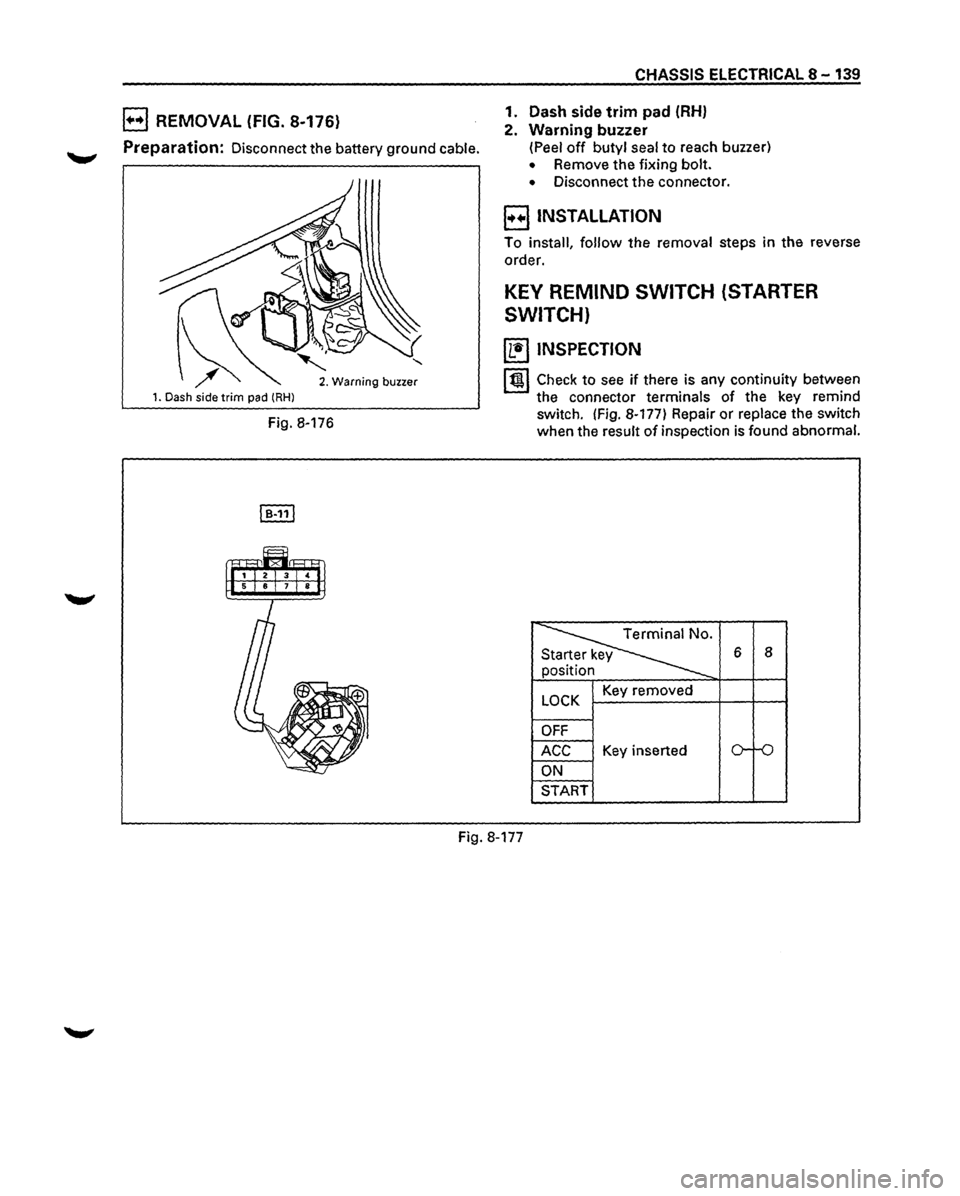
KEY REMIND SWITCH (STARTER
SWITCH)
~ INSPECTION
I t!tl Check to see if there is any continuity between
the connector terminals of the key remind
switch. (Fig. 8-177) Repair
or replace the switch
when the result
of inspection is found abnormal.
~
6 8
n
y
LOCK Key removed
OFF
ACC Key inserted o-ro
ON
START
Fig. 8-177
Page 1332 of 1928
8-142 CHASSIS ELECTRICAL
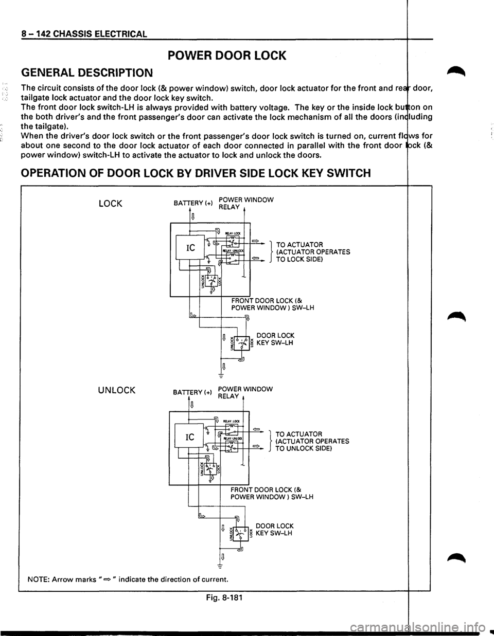
POWER DOOR LOCK
GENERAL DESCRIPTION
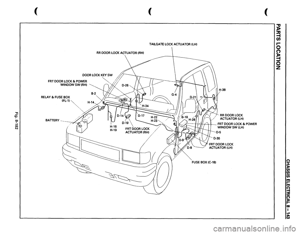
The circuit consists of the door lock (& power window) switch, door lock actuator for the front and rea door,
tailgate
lock actuator and the door lock key switch.
The
front door lock switch-LH is always provided with battery voltage. The key or the inside lock bu on on
the both driver's and the
front passenger's door can activate the lock mechanism of all the doors (in< luding
the tailgate).
When the driver's
door lock switch or the front passenger's door lock switch is turned on, current fie ws for
about one second to the door lock actuator of each door connected in parallel with the front door ock (&
power window) switch-LH to activate the actuator to lock and unlock the doors.
OPERATION OF DOOR LOCK BY DRIVER SIDE LOCK KEY SWITCH
LOCK
UNLOCK
BATTERY(+) POWER WINDOW RELAY
.....-1::::::;---'li) ~
fi ::> ~ = } TO ACTUATOR IC IE~CC (ACTUATOR OPERATES
I l lj~:.-.>+T++==-TO LOCK SIDE)
W=~~~~'l g
Jlf!
FRONT DOOR LOCK (& POWER WINDOW l SW-LH
sb2-f---+---w
U ~rh;±,i DOOR LOCK ~LfJg KEY SW-LH
u =
BATTERY(+) POWER WINDOW RELAY
,..,~T =
I IEl.
CS ~:t-o·++ 1+==-TO UNLOCK SIDE)
IL...t=:t=~~w.~ g
~q;J
FRONT DOOR LOCK (& POWER WINDOW) SW-LH
[b =
U ~8 DOOR LOCK
~l.f} KEY SW-LH
NOTE: Arrow marks"=" indicate the direction of current.
Fig. 8-181
IIIII
Page 1333 of 1928
"T1 !0 (X) I ... (X) N
(
RR
DOOR
LOCK
ACTUATOR
(RHI
DOOR
LOCK
KEY
SW
"-
FRT
DOOR
LOCK
& POWER
WINDOW SW
(RHI
RELAY
& FUSE
BOX (FL-11~
BATTERY
' ,,
( TAILGATE
LOCK
ACTUATOR
(LHI
RR
DOOR
LOCK
ACTUATOR
(LHI
h.=
I //If/:
I
FRT
DOOR
LOCK
& POWER
WINDOW
SW
(LHI
FRT
DOOR
LOCK
ACTUATOR
(LHI
FUSE
BOX
(C-181
(
~ ~ r-0 n ~ 0
2
(") J: )> en
en (i) m rm ~ :a g reo I ...a t
Page 1339 of 1928
CHASSIS ELECTRICAL 8 -149
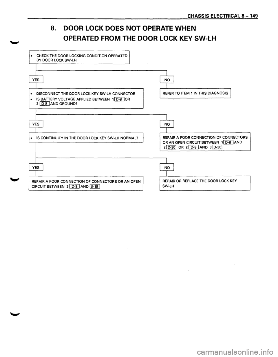
8. DOOR LOCK DOES NOT OPERATE WHEN
OPERATED FROM THE DOOR LOCK KEY SW-LH
• CHECK THE DOOR LOCKING CONDITION OPERATED
BY DOOR LOCK SW-LH
l
YES I NO l
1
• DISCONNECT THE DOOR LOCK KEY SW-LH CONNECTOR REFER TO ITEM 1 IN THIS DIAGNOSIS l
• IS BATTERY VOLTAGE APPLIED BETWEEN 1 I D-8 lOR
2 [Q]JAND GROUND?
I
YES I NO I
I
• IS CONTINUITY IN THE DOOR LOCK KEY SW-LH NORMAL? REPAIR A POOR CONNECTION OF CONNECTORS
OR AN OPEN CIRCUIT BETWEEN 1~AND
2ID-30I OR 2[@AND 3ID-30I
I
YES I NO l
I
REPAIR A POOR CONNECTION OF CONNECTORS OR AN OPEN REPAIR OR REPLACE THE DOOR LOCK KEY
CIRCUIT BETWEEN 3 [];[]AND IB-18 I SW-LH
Page 1340 of 1928
8 -150 CHASSIS ELECTRICAL
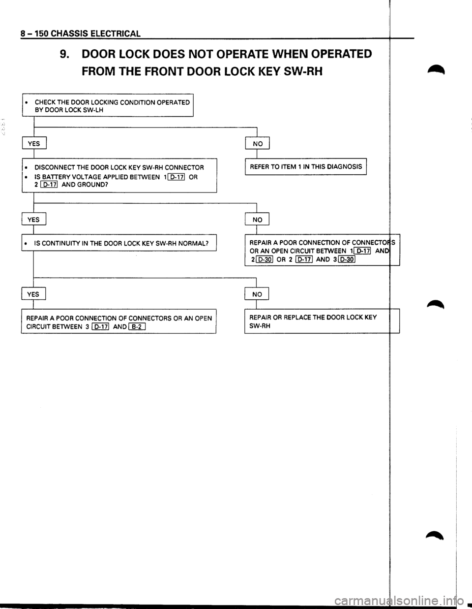
9. DOOR LOCK DOES NOT OPERATE WHEN OPERATED
FROM THE FRONT DOOR LOCK KEY SW-RH
• CHECK THE DOOR LOCKING CONDITION OPERATED BY DOOR LOCK SW-LH
YES I
• DISCONNECT THE DOOR LOCK KEY SW-RH CONNECTOR
• ISBATTERYVOLTAGEAPPLIEDBETWEEN 1ID-171 OR 21 D-171 AND GROUND?
YES I
• IS CONTINUITY IN THE DOOR LOCK KEY SW-RH NORMAL?
YES I
REPAIR A POOR CONNECTION OF CONNECTORS OR AN OPEN
CIRCUIT BETWEEN 31 D-171 AND(]]]
I
NO I
I
REFER TO ITEM 1 IN THIS DIAGNOSIS l
I
NO I
I
REPAIR A POOR CONNECTION OF CONNECTO S
OR AN OPEN CIRCUIT BETWEEN 11 D-171 ANC
2ID-30I OR 2ID-17I AND 3ID-30I
I
NO I
I
REPAIR OR REPLACE THE DOOR LOCK KEY
SW-RH
•
Page 1343 of 1928
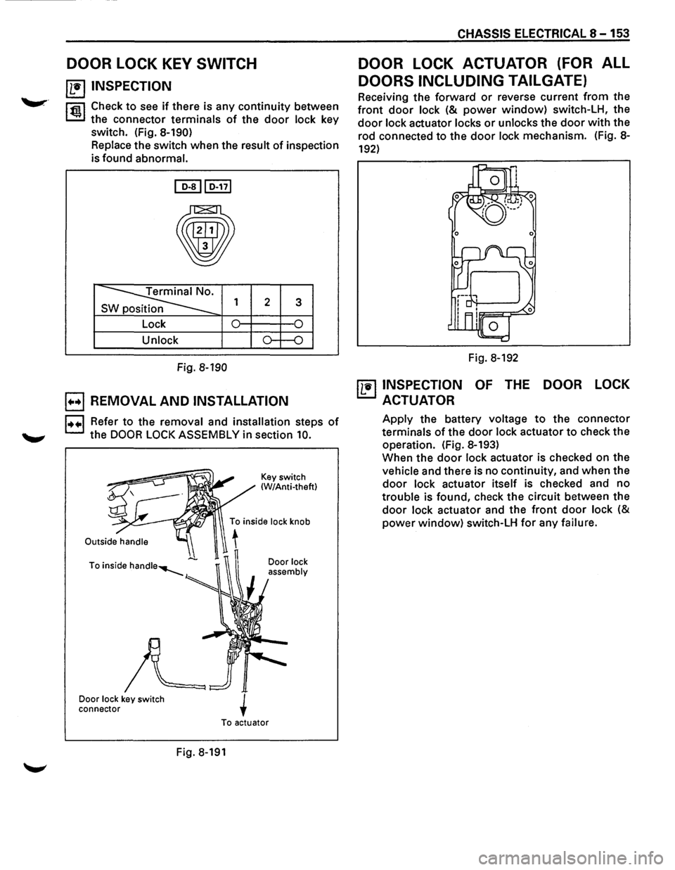
DOOR LOCK KEY SWITCH
~ INSPECTION
l'fiil Check to see if there is any continuity between
~ the connector terminals of the door lock key
switch. (Fig.
8-190)
Replace the switch when the result of inspection
is found abnormal.
~lo-nl
•
~ s 1 2 3
Lock 0 0
Unlock o--o
Fig. 8-190
E) REMOVAL AND INSTALLATION
1••1 Refer to the removal and installation steps of
the DOOR LOCK ASSEMBLY in section 10.
Door lock key switch
connector Key
switch
(W/Anti-theft)
Door
lock
assembly
To actuator
Fig. 8-191
CHASSIS ELECTRICAL 8 -153
DOOR LOCK ACTUATOR (FOR ALL
DOORS INCLUDING TAILGATE)
Receiving the forward or reverse current from the
front door lock (& power window) switch-LH, the
door lock actuator locks or unlocks the door with the
rod connected
to the door lock mechanism. (Fig. 8-
192)
Fig. 8-192
~ INSPECTION OF THE DOOR LOCK
ACTUATOR
Apply the battery voltage to the connector
terminals
of the door lock actuator to check the
operation. (Fig. 8-193)
When the
door lock actuator is checked on the
vehicle and there is no continuity, and when the
door lock actuator itself is checked and no
trouble is found, check the circuit between the
door lock actuator and the front door lock (&
power window) switch-LH for any failure.
Page 1461 of 1928
'"T1 !fl' co I w _. (11
I i i, ~
(
RR
DOOR
LOCK
ACTUATOR
{RHJ
FRT
DOOR
LOCK
SW
(RH
FRT
DOOR
KEY
SW,
(RH),
( ANTI-THEFT
CONTROLLER
RR
DOOR
SW
(RHJ
-------
FRT
DOOR
SW,
(RH)
.~""··
\
/;'~
~
"'··
FRT
DOOR
LOCK
ACTUATOR
(RH)
'-, ..,/j.
',
H-14
'L
y'JIJ.
"·,
H-15"
82
ANTI-THEFT
HORN~-20
"-,
-
RELAY
& FUSE
BOX
~
{FL-1,
FL-2,
F-3)
~
RELAY:
STARTER BATTERY
X::
H-41 B-39 DIODE
B-40 DIODE
B-43 DIODE FUSE
BOX MODESW
TRANSMISSION ,
TAILGATE
LOCK
ACTUATOR
TAILGATE
KEY
SW
TAILGATESW
FRT
DOOR
LOCK
&
/'POWER
WINDOW
SW
H-37 H-38 RRDOOR SW,(LH)
.
RR
DOOR
LOCK
-~ACTUATOR
{LHJ
FRT
DOOR
KEY
SW,
{LH)
-H-28,
H-29
FRT
DOOR
LOCK
ACTUA
TOR
(LH)
(
;g ~ C/) 5 C') ~ 0 z
n :X: ~ (/) 0 m rm ~ n ):a r-0) I N ..... -