key battery ISUZU TROOPER 1995 User Guide
[x] Cancel search | Manufacturer: ISUZU, Model Year: 1995, Model line: TROOPER, Model: ISUZU TROOPER 1995Pages: 1928
Page 690 of 1928
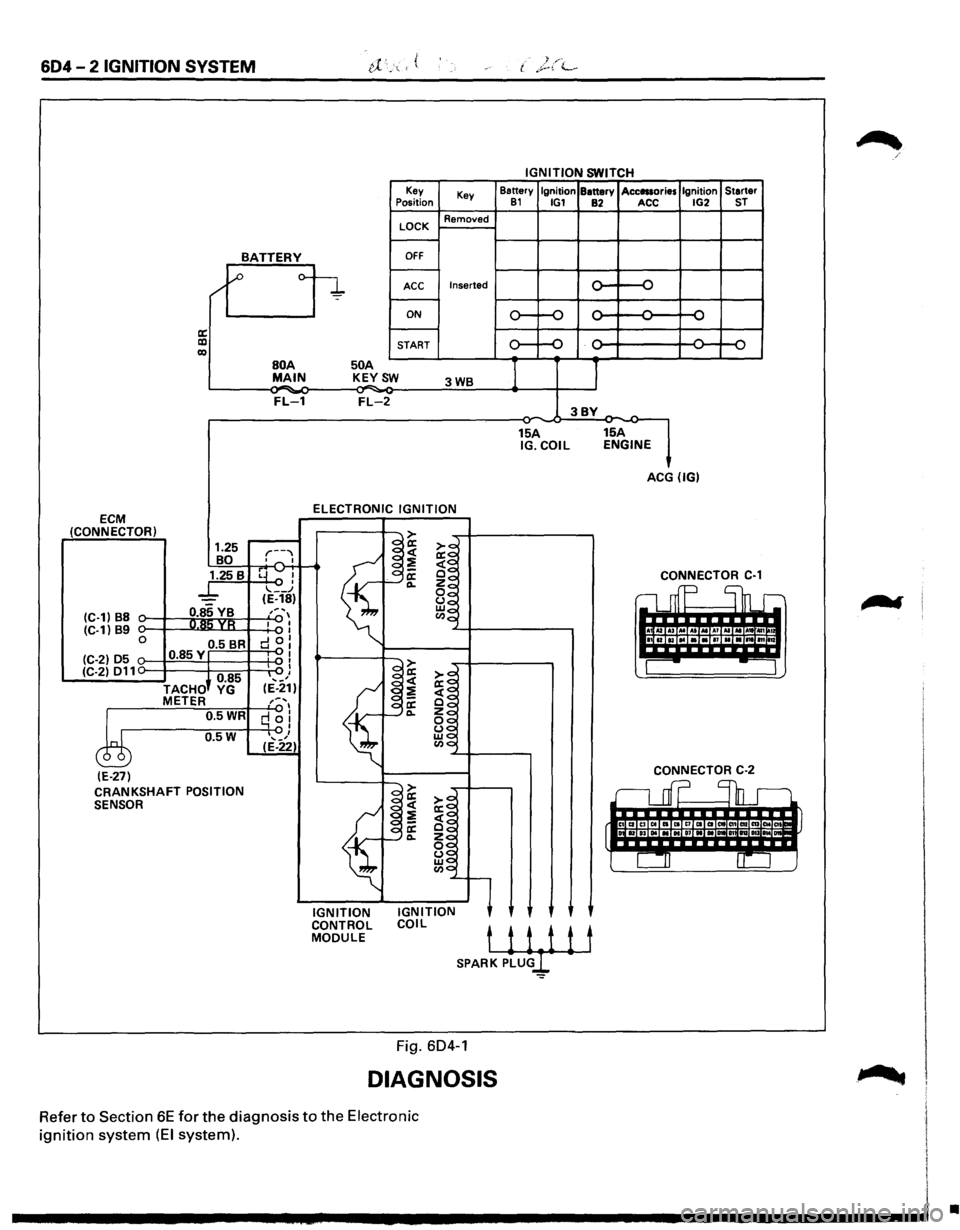
604-2 IGNITION SYSTEM
IGNITION SWITCH
Key
Key Battery
Ignition Battery Acc111ories Ignition
Starter Position 81 IG1 82 ACC IG2 ST
LOCK Removed
BATTERY OFF
/'1 ~ o-
~ Inserted ...... {) ACC ..., -
ON ...... ..... ...... ...... ...... ~ -.....
a: ...... -lXI START Q II) '-' '-' ...., ,_,
BOA 50 A
I 1 MAIN K~YSW 3WB
FL-1 FL-2 3BY -15A 15A IG.COIL ENGINE
ACG (IG)
ELECTRONIC
IGNITION ECM (CONNECTOR) > 1.25 r--""
~~ ~~ BO o""' I
~
1.25 B rrvl -~~ ' f"--~ CONNECTOR C-1
_l_ .... __ .J ~~ c1 mp Shr (E-18)
(C-1) B8 0.85 VB ,, ... , ~~ R!'i YR I I Cl.lo
I !ita lui (C-1) 89 I 0 0.5 BR d 0: IBIBIIIINIBI111Io
(C-2) 05 0.85Y "'I I I > ---(C-2) 011 I
I
)+ 0.85 '-'I a:
~~ ,_, <( TACHO YG (E-21)
~
;;!] METER ,:. .... , a: ~~ 0.5WR q 0! 0... ~~
0.5W I ~$ ... _, ~0 c ( (E-22)
(E-27) CONNECTOR C-2
CRANKSHAFT POSITION .::::> rL
r;::::l enD. .-SENSOR I~ ~~
~ ~ ~~ rt~·· IC4 IT>TiiTiil
f §~
~g l CIJ 0::
·~'l
IGNITION IGNITION CONTROL
COIL MODULE tii1it SPARK PLU
DIAGNOSIS
Refer to Section 6E for the diagnosis to the Electronic
ignition system (EI system).
•
Page 700 of 1928
6E2-4 DRIVEABILITY AND EMISSIONS
BASIC KNOWLEDGE REQUIRED
Before using this section of the Service Manual,
there are some areas that you should be familiar
with. Without this basic knowledge, you will have
trouble using the diagnostic procedures
contained in this section.
BASIC ELECTRIC CIRCUITS
You should understand the basic theory of
electricity, and know the meaning of voltage,
amps, and ohms. You should understand what
happens in a circuit with an open or a shorted
wire. You
should be able to read and understand a
wiring diagram. A shortto ground is referred to as
a ground to distinguish it from a short between
wires.
USE OF CIRCUIT TESTING TOOLS
You should know how to use a test light, how to
connect and use a tachometer, and
how to use
jumper wires to by-pass components to test
circuits. Care
should be taken to not deform the
terminal when testing.
USE OF DIGITAL VOLT-OHM METER
(DVOM)
You should be familiar with the Digital Volt-Ohm
Meter, particularly special tool J-39200 or
equivalent. You should be able to measure
voltage, resistance, and current and know how to
use the meter correctly.
The
Digital Volt-Ohm Meter is covered in the
"Special Tools" portion of this section.
DIAGNOSTIC INFORMATION
The diagnostic "Trouble Tree" charts and func
tional checks in this manual are designed to locate
a faulty circuit or component through logic based
on the process
of elimination. The charts are
prepared
with the requirement that the vehicle
functioned correctly at the time of assembly and
that there are no multiple failures.
The Engine Control Module (ECM) performs a
continual self-diagnosis on certain control
functions. This diagnostic capability is
complemented by the diagnostic procedures
contained in this
manual. The ECM's language for
communicating the source of a malfunction is a
system
of Diagnostic Trouble Codes (DTCs). The
DTC(s) are
two or three digit numbers that can
range from12 to
51. When a malfunction is
detected by the ECM, a DTC is set and the
Malfunction Indicator Lamp is illuminated.
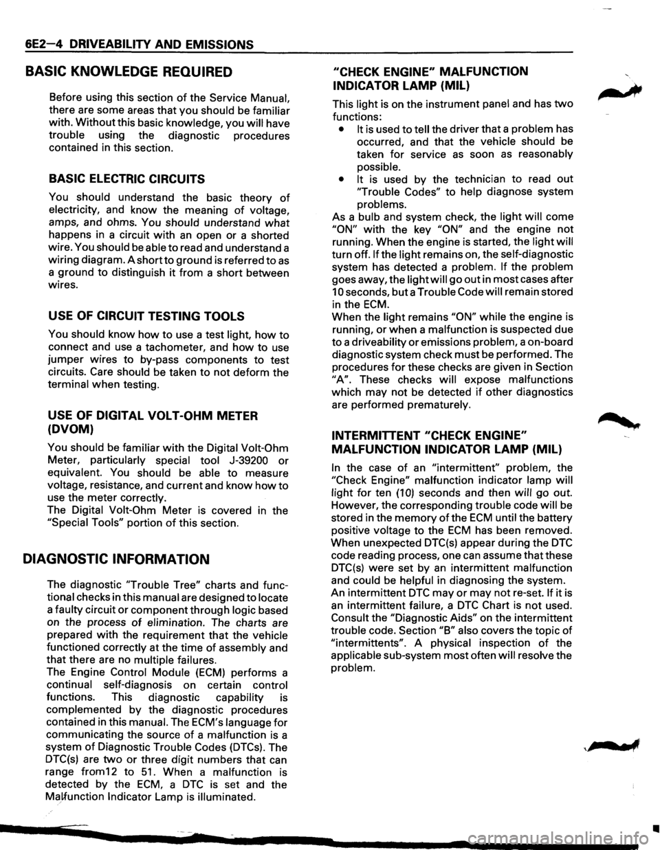
"CHECK ENGINE" MALFUNCTION
INDICATOR
LAMP (MIL)
This light is on the instrument panel and has two
functions:
• It is used to tell the driver that a problem has
occurred, and that the
vehicle should be
taken
for service as soon as reasonably
possible.
• It
is used by the technician to read out
'Trouble Codes" to help diagnose system
problems.
As a bulb and system check, the light will come
"ON" with the key "ON" and the engine not
running. When the engine is started, the light will
turn off. If the light remains on, the self-diagnostic
system has detected a
problem. If the problem
goes away, the light will go out in most cases after
10 seconds, but a Trouble Code will remain stored
in the
ECM.
When the light remains "ON" while the engine is
running,
or when a malfunction is suspected due
to a
driveability or emissions problem, a on-board
diagnostic system check
must be performed. The
procedures
for these checks are given in Section
"A". These checks will expose malfunctions
which may
not be detected if other diagnostics
are performed
prematurely.
INTERMITTENT "CHECK ENGINE"
MALFUNCTION INDICATOR
LAMP (MIL)
In the case of an "intermittent" problem, the
"Check Engine"
malfunction indicator lamp will
light
for ten (1 0) seconds and then will go out.
However, the corresponding
trouble code will be
stored in the
memory of the ECM until the battery
positive
voltage to the ECM has been removed.
When unexpected DTC(s) appear during the
DTC
code reading process, one can assume that these
DTC(s) were set by an intermittent malfunction
and could be helpful in diagnosing the system.
An intermittent
DTC may or may not re-set. If it is
an intermittent failure, a DTC Chart is not used.
Consult the "Diagnostic Aids" on the intermittent
trouble code. Section "B" also covers the topic of
"intermittents". A physical inspection of the
applicable sub-system most often will resolve the
problem.
II
Page 701 of 1928
......, .., LU
READING DIAGNOSTIC TROUBLE CODES
(Fig. 6E2-1)
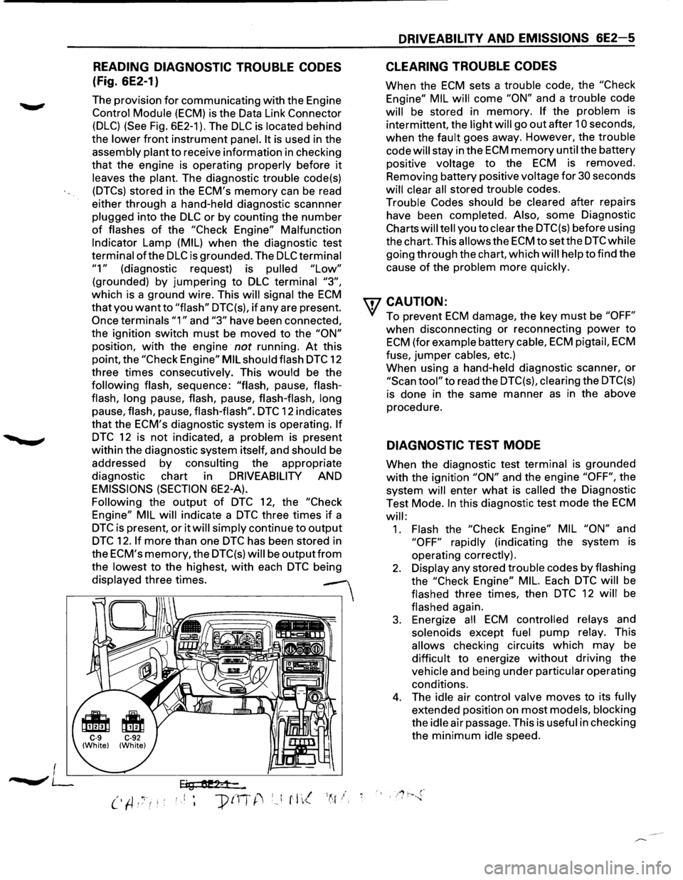
The provision for communicating with the Engine
Control Module (ECM) is the Data Link Connector
(DLC) (See Fig. 6E2-1 ). The DLC is located behind
the
lower front instrument panel. It is used in the
assembly plant
to receive information in checking
that the engine is operating properly before it
leaves the plant. The diagnostic trouble code(s)
(DTCs) stored in the ECM's memory can be read
either through a hand-held diagnostic scannner
plugged into the
DLC or by counting the number
of flashes of the "Check Engine" Malfunction
Indicator Lamp (MIL) when the diagnostic test
terminal
ofthe DLC is grounded. The DLC terminal
"1" (diagnostic request) is pulled "Low"
(grounded) by jumpering to DLC terminal "3",
which is a ground wire. This will signal the ECM
that you want to "flash" DTC(s), if any are present.
Once terminals "1" and "3" have been connected,
the ignition switch
must be moved to the "ON"
position, with the engine not running. At this
point, the
"Check Engine" MIL should flash DTC 12
three times consecutively. This
would be the
following flash, sequence: "flash, pause, flash
flash,
long pause, flash, pause, flash-flash, long
pause, flash, pause, flash-flash". DTC 12 indicates
that the ECM's diagnostic system is operating.
If
DTC 12 is not indicated, a problem is present
within the diagnostic system itself, and should be
addressed
by consulting the appropriate
diagnostic chart in
DRIVEABILITY AND
EMISSIONS (SECTION 6E2-A).
Following the output of DTC 12, the "Check
Engine" MIL
will indicate a DTC three times if a
DTC is present, or it will simply continue to output
DTC 12. If more than one DTC has been stored in
the
ECM's memory, the DTC(s) will be outputfrom
the lowest to the highest, with each DTC being
displayed three times.
--
Eig tU!2-1-...
DRIVEABILITY AND EMISSIONS 6E2-5
CLEARING TROUBLE CODES
When the ECM sets a trouble code, the "Check
Engine" MIL
will come "ON" and a trouble code
will be stored in memory. If the problem is
intermittent, the light
will go out after 10 seconds,
when the fault goes away. However, the trouble
code
will stay in the ECM memory until the battery
positive voltage
to the ECM is removed.
Removing battery positive voltage
for 30 seconds
will clear all stored trouble codes.
Trouble
Codes should be cleared after repairs
have been completed. Also, some Diagnostic
Charts will tell you to clear the DTC(s) before using
the chart. This
allows the ECM tosetthe DTCwhile
going through the chart, which will help to find the
cause
of the problem more quickly.
wcAUTION:
• To prevent ECM damage, the key must be "OFF"
when disconnecting or reconnecting power to
ECM (for example battery cable, ECM pigtail, ECM
fuse, jumper cables, etc.)
When using a hand-held diagnostic scanner,
or
"Scan tool" to read the DTC(s), clearing the DTC(s)
is done in the same manner as in the above
procedure.
DIAGNOSTIC TEST MODE
When the diagnostic test terminal is grounded
with the ignition "ON" and the engine "OFF", the
system
will enter what is called the Diagnostic
Test Mode.
In this diagnostic test mode the ECM
will:
1. Flash the "Check Engine" MIL "ON" and
"OFF" rapidly (indicating the system is
operating correctly).
2. Display any stored trouble codes by flashing
the
"Check Engine" MIL. Each DTC will be
flashed three times, then
DTC 12 will be
flashed again.
3. Energize all ECM controlled relays and
solenoids except
fuel pump relay. This
allows checking circuits which may be
difficult to energize without driving the
vehicle and being under particular operating
conditions.
4. The idle air control valve moves to its fully
extended position on most models, blocking
the
idle air passage. This is useful in checking
the
minimum idle speed.
Page 729 of 1928
DRIVEABILITY AND EMISSIONS 6E2-33
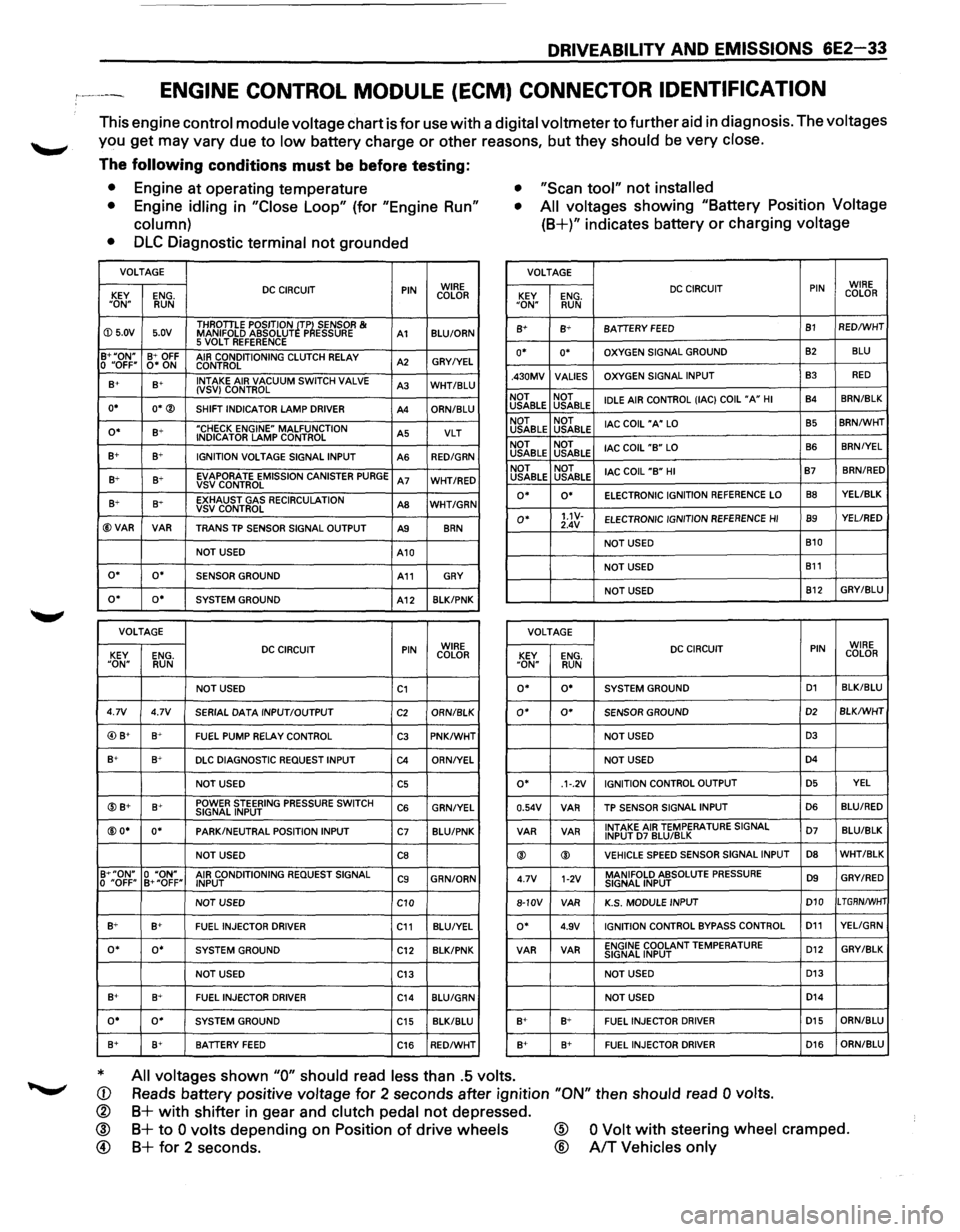
ENGINE CONTROL MODULE (ECM) CONNECTOR IDENTIFICATION
This engine control module voltage chart is for use with a digital voltmeter to further aid in diagnosis. The voltages
you get may vary due to low battery charge or other reasons, but they should be very close.
The following conditions must be before testing:
• Engine at operating temperature • "Scan tool" not installed
•
Engine idling in "Close Loop" (for "Engine Run"
column) •
All voltages showing "Battery Position Voltage
(8+)" indicates battery or charging voltage
•
DLC Diagnostic terminal not grounded
VOLTAGE VOLTAGE
DC CIRCUIT PIN WIRE
KEY ENG. COLOR
"ON" RUN
DC CIRCUIT PIN WIRE
KEY ENG. COLOR "ON" RUN
ID 5.0V 5.0V THROTILE
POSITION ~TP~ SENSOR & MANIFOLD ABSOLUT P ESSURE A1 BLU/ORN 8+ B+ BATIERY FEED B1 RED/WHT
5 VOLT REFERENCE B+"ON" B+ OFF AIR CONDITIONING CLUTCH RELAY A2 GRY/YEL 0 "OFF" 0* ON
CONTROL o• o• OXYGEN SIGNAL GROUND 82 BLU
B+ s+ INTAKE
AIR VACUUM SWITCH VALVE A3 WHT/BLU (VSV) CONTROL
o• O*® SHIFT INDICATOR LAMP DRIVER A4 ORN/BLU .430MV
VALlES OXYGEN
SIGNAL INPUT
B3 RED
NOT NOT
IDLE AIR CONTROL (lAC) COIL "A" HI B4 8RN/BLK USABLE
USABLE
o• B+ "CHECK ENGINE" MALFUNCTION A5 VLT INDICATOR LAMP CONTROL
B+ B+ IGNITION VOLTAGE SIGNAL INPUT
AS RED/GRN
NOT NOT
lAC COIL "A" LO B5 8RN/WHT USABLE USABLE
NOT NOT
lAC COIL
"B" LO B6 BRN/YEL USABLE
USABLE
B+ B+ EVAPORATE EMISSION CANISTER PURGE A7 WHT/RED VSVCONTROL NOT
NOT
lAC COIL "B" HI B7 BRN/RED USABLE
USABLE
B+ 8~ EXHAUST GAS RECIRCULATION AS WHT/GRN VSV CONTROL
@VAR VAR TRANS TP SENSOR SIGNAL OUTPUT A9 8RN
o• o• ELECTRONIC IGNITION REFERENCE LO 88 YEL/BLK
o• 1.1V-ELECTRONIC
IGNITION REFERENCE HI B9 YEL/RED
2.4V
NOT USED B10
NOT USED
A10
NOT USED
B11 o• o• SENSOR GROUND A11 GRY
NOT USED B12 GRY/BLU o• o• SYSTEM
GROUND A12 8LK/PNK
VOLTAGE
VOLTAGE
DC CIRCUIT PIN WIRE
KEY ENG. COLOR DC CIRCUIT PIN WIRE
KEY ENG. COLOR "ON" RUN "ON" RUN
NOT USED C1 o• o• SYSTEM GROUND D1 BLK/BLU
4.7V 4.7V
SERIAL DATA INPUT/OUTPUT C2 ORN/8LK o• 0* SENSOR GROUND D2 BLK/WHT
@) B+ B+ FUEL PUMP RELAY CONTROL C3 PNK/WHT NOT USED D3
B+ B+ DLC DIAGNOSTIC REQUEST INPUT C4 ORN/YEL NOT USED D4
NOT USED C5 o• .1·.2V IGNITION
CONTROL OUTPUT D5 YEL
@B+ B+ POWER STEERING PRESSURE SWITCH C6 GRN/YEL SIGNAL INPUT 0.54V VAR
TP SENSOR
SIGNAL INPUT D6 BLU/RED
@O* o• PARK/NEUTRAL POSITION
INPUT C7 BLU/PNK VAR
VAR INTAKE AIR TEMPERATURE SIGNAL D7 BLU/BLK INPUT D7 BLU/BLK
NOT USED CB ® ® VEHICLE SPEED SENSOR
SIGNAL INPUT D8 WHT/BLK
B+"ON" 0 "ON" AIR CONDITIONING REQUEST SIGNAL C9 GRN/ORN
0 "OFF" B+"OFF"
INPUT 4.7V 1-2V MANIFOLD ABSOLUTE PRESSURE D9 GRY/RED SIGNAL
INPUT
NOT USED
C10 8-10V
VAR K.S.
MODULE INPUT D10 LTGRN/WHT
B+ B+ FUEL INJECTOR
DRIVER C11 BLU/YEL o• 4.9V IGNITION CONTROL BYPASS CONTROL D11 YELIGRN
o• o• SYSTEM GROUND
C12 BLK/PNK VAR VAR ENGINE COOLANT TEMPERATURE
D12 GRY/BLK SIGNAL
INPUT
NOT USED
C13 NOT USED D13
B+ 8+
FUEL INJECTOR DRIVER C14 BLU/GRN NOT USED D14
o• o• SYSTEM GROUND
C15 BLK/BLU B+ B+ FUEL INJECTOR DRIVER D15 ORN/BLU
8+ B+ BATIERY FEED C16 RED/WHT B+ 8+
FUEL INJECTOR DRIVER D16 ORN/8LU
* All voltages shown "0" should read less than .5 volts.
Reads battery positive voltage for 2 seconds after ignition "ON" then should read 0 volts. CD
®
® @
B+ with shifter in gear and clutch pedal not depressed.
B+ to 0 volts depending on Position of drive wheels
B+ for 2 seconds.
@
®
0 Volt with steering wheel cramped.
A/T Vehicles only
Page 744 of 1928
6E2-48 DRIVEABILITY AND EMISSIONS
CHART A-5
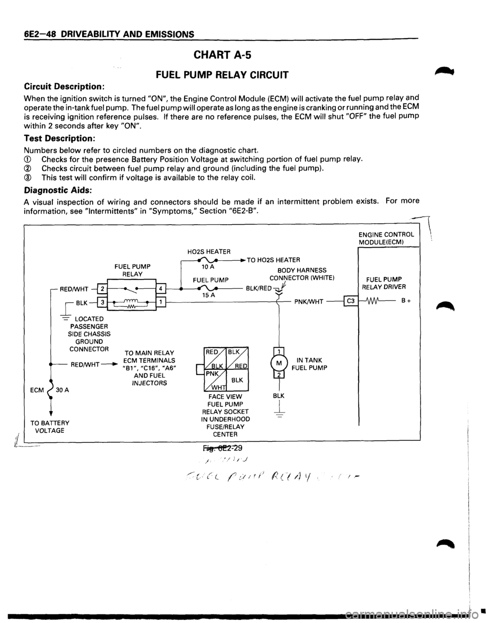
FUEL PUMP RELAY CIRCUIT
Circuit Description:
When the ignition switch is turned "ON", the Engine Control Module (ECM) will activate the ft:Jel pump relay and
operate the in-tank
fuel pump. The fuel pump will operate as long as the engine is cranking or running and the ECM
is receiving ignition reference pulses. If there are no reference pulses, the ECM will shut "OFF" the fuel pump
within 2 seconds after key
"ON".
Test Description:
Numbers below refer to circled numbers on the diagnostic chart.
CD Checks for the presence Battery Position Voltage at switching portion of fuel pump relay.
® Checks circuit between fuel pump relay and ground (including the fuel pump).
® This test will confirm if voltage is available to the relay coil.
Diagnostic Aids:
A visual inspection of wiring and connectors should be made if an intermittent problem exists. For more
information, see
"lntermittents" in "Symptoms," Section "6E2-B".
ECM
FUEL PUMP
RELAY
H02S HEATER _. ___ .,.TO H02S HEATER
10 A BODY HARNESS CONNECTOR (WHITE)
RED/WHT 1---_.__.., '"..._.. __ BLK!RED...J
_[BLK
-= LOCATED PASSENGER SIDE CHASSIS
GROUND
CONNECTOR
TO MAIN RELAY
RED/WHT---+-ECM TERMINALS "81", "C16", 11A6" AND FUEL INJECTORS
FACE VIEW FUEL PUMP RELAY SOCKET
BLK
j__
IN TANK FUEL PUMP
TO BATIERY IN UNDERHOOD ENGINE
CONTRO:-- MODULE(ECM) ·.
FUEL PUMP RELAY DRIVER
8+
VOLTAGE
FUSE/RELAY
i L---------------------------C-EN_T_E_R _______________________ ~
lL---f~. 6E2=29
/
'"·:c·t( (7.::!11t.~ l<(/1) 1/. i-
•
Page 761 of 1928
®
DRIVEABILITY AND EMISSIONS 6E2-65
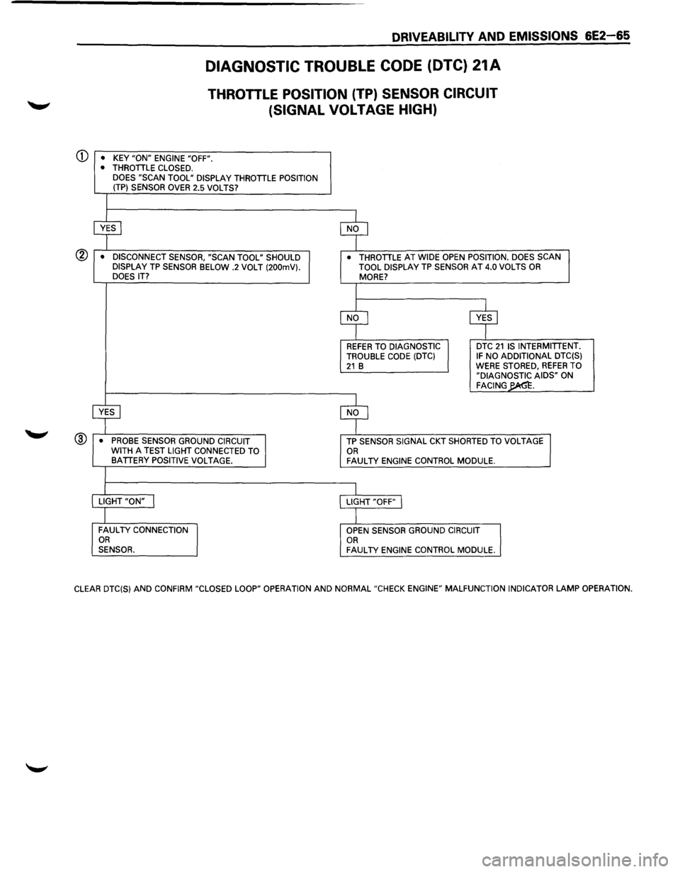
DIAGNOSTIC TROUBLE CODE (DTC) 21A
THROTILE POSITION (TP) SENSOR CIRCUIT
(SIGNAL
VOLTAGE HIGH)
• KEY "ON" ENGINE "OFF". • THROTTLE CLOSED.
DOES "SCAN TOOL" DISPLAY THROTTLE POSITION
(TP) SENSOR OVER 2.5 VOLTS?
$ $
• DISCONNECT SENSOR, "SCAN TOOL" SHOULD • THROTTLE AT WIDE OPEN POSITION. DOES SCAN
DISPLAY TP SENSOR BELOW .2 VOLT (200mV}. TOOL DISPLAY TP SENSOR AT 4.0 VOLTS OR
DOES IT? MORE?
I
$ cvr
REFER TO DIAGNOSTIC DTC 21 IS
INTERMITTENT.
TROUBLE CODE (DTC} IF NO ADDITIONAL DTC(S} 21 B WERE STORED, REFER TO
"DIAGNOSTIC AIDS" ON FACING~.
~ $
• PROBE SENSOR GROUND CIRCUIT TP SENSOR SIGNAL CKT SHORTED TO VOLTAGE
WITH A TEST LIGHT CONNECTED TO OR BATTERY POSITIVE VOLTAGE. FAULTY ENGINE CONTROL MODULE.
I LIGHT "ON" I LIGHT "OFF" I
I FAULTY CONNECTION
OPEN SENSOR GROUND CIRCUIT OR
OR SENSOR. FAULTY ENGINE CONTROL MODULE.
CLEAR DTC(S}
AND CONFIRM "CLOSED LOOP" OPERATION AND NORMAL "CHECK ENGINE" MALFUNCTION INDICATOR LAMP OPERATION.
Page 835 of 1928
RESULTS OF INCORRECT OPERATION
An open or ground in the Ignition Control (I C) or bypass
circuits
will set a Diagnostic Trouble Code (DTC) 42 and
cause the engine
to run on the Ignition Control Module
(ICM)
timing.
The Engine
Control Module (ECM) uses information
from the Intake Air Temperature (IAT) and engine
coolant sensors in addition to revolution per minute
(rpm) to
calculate spark advance as follows:
• Cold
engine -more spark advance.
• Engine under minimum load based on rpm and
low amount of air flow = more spark advance.
• Hot engine = less spark advance.
• Engine under heavy load based on rpm and high
air
flow = less spark advance.
HOW DIAGNOSTIC TROUBLE CODE (DTC)
42 IS DETERMINED
When the system is running on the ICM, that is, no
voltage on the bypass line, the ICM grounds (GND) the
IC signal. The ECM expects to see no voltage on the IC
line during this condition.lf it sees a voltage, it sets DTC
42 and will not go into the IC mode.
DRIVEABILITY AND EMISSIONS 6E2-139
When the rpm for IC is reached (about 400 rpm) the
ECM applies 5 volts to the bypass line and the IC should
no longer be grounded in the ICM so the IC voltage
should
be varying.
An open in the
IC circuit while running, will result in the
engine continuing to run, but in a back-up
ig~it~on
timing mode (module timing) at a calculated t1mmg
value
and the malfunction indicator lamp will not be
"ON".
If
the IC circuit is shorted to GND, the "Check Engine"
malfunction
indicator lamp will be turned "ON", and a
DTC 42 will be set and the engine will operate in
module timing. Either condition may cause poor
performance and reduced
fuel economy.
If the bypass line is open or GND, the ICM will not
switch to IC mode so the IC voltage will be low and DTC
42 will be set.
If the IC line is grounded, the ICM will switch to IC, but
because the line isGNDtherewill be no ICsignai.A DTC
42 will be set.
DIAGNOSIS
If the engine cranks but will not run, CHART A-3 will be
used to determine if the Electronic Ignition (EI) system
is the cause
of the problem or if it is another part of the
fuel injection system.
If DTC 42 is set, that DTC chart should be used for
diagnosis. If no DTC is set and the ignition system is
suspected, use
CHART C4-D ("EI" Misfire) for
diagnosis.
DIAGNOSTIC TROUBLE CODE (DTC) 12
DTC 12 is used during the on-board diagnostic system
check procedure to test the
DTC display ability of the
ECM. This diagnostic trouble code indicates that the
ECM is not receiving the engine speed (REFERENCE)
signal. This occurs with the ignition key "ON" and the
engine not running.
The "reference"
signal also triggers the fuel injection
system.
Without the "reference" signal the engine
cannot run.
ON-VEHICLE SERVICE
ELECTRONIC IGNITION (EI) ASSEMBLY
1••1 REMOVE OR DISCONNECT
1. Negative battery cable
2. "EI" electrical connectors (3)
3. Spark plug wires. (Note wire positions to proper
coils) (6)
4. "EI" assembly to bracket bolts (3)
5. "EI" assembly from Intake Plenum.
1••1 INSTALL OR CONNECT
1. "EI" assembly bracket to Intake Plenum
Tighten bolts to 25 N·m (19 lb·ft)
2. Spark plug wires to correct spark plugs
3. "EI" electrical connectors
4. Negative battery cable
Page 920 of 1928
7 A-48 AUTOMATIC TRANSMISSION (4L30-E)
"CHECK TRANS" CHECK
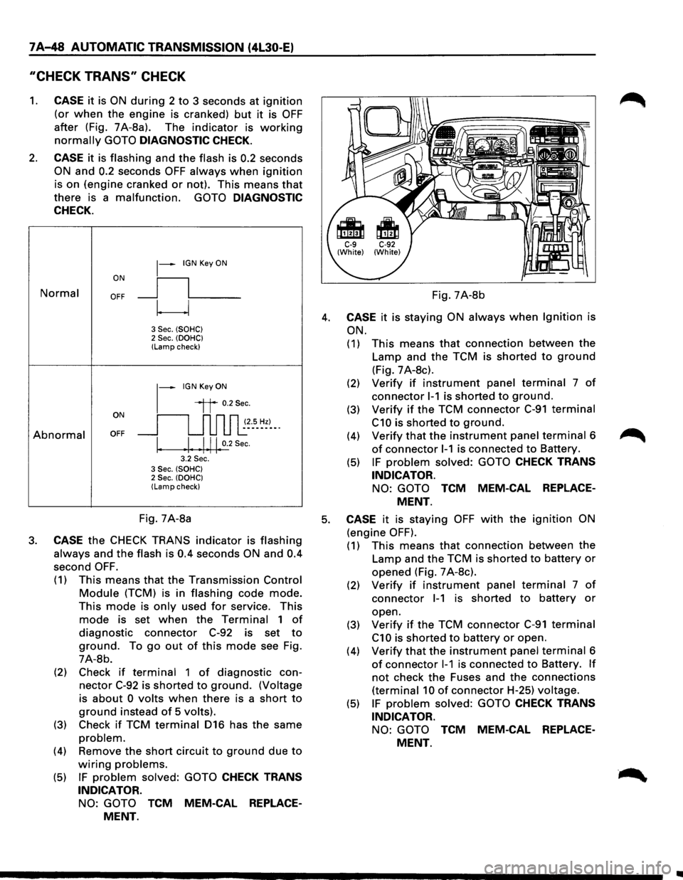
1. CASE it is ON during 2 to 3 seconds at ignition
(or when the engine is cranked) but it is OFF
after (Fig. 7A-8a). The indicator is working
normally GOTO DIAGNOSTIC CHECK.
2. CASE it is flashing and the flash is 0.2 seconds
ON and 0.2 seconds OFF always when ignition
is on (engine cranked or not). This means that
there is a malfunction. GOTO DIAGNOSTIC
CHECK.
Normal
Abnormal
~-IGN Key ON
ON
II
OFF __j l___
~
3 Sec. (SOHC) 2 Sec. (OOHC) (Lamp check)
1-
IGN Key ON
il 0.2Sec.
oN 11 n n n ~~--s_ ~~)-_. OFF __j u u u l:
I. .I. .1.11. 0.2
Sec.
3.2 Sec. 3 Sec. (SOHC) 2 Sec. (OOHC) (Lamp check)
Fig. 7A-8b
4. CASE it is staying ON always when Ignition is
ON.
(1) This means that connection between the
Lamp and the TCM is shorted to ground
(Fig. 7 A-8c).
(2) Verify if instrument panel terminal 7 of
connector 1-1 is shorted to ground.
(3) Verify if the TCM connector C-91 terminal
C10 is shorted to ground.
(4) Verify that the instrument panel terminal 6
of connector 1-1 is connected to Battery.
(5) IF problem solved: GOTO CHECK TRANS
INDICATOR.
NO: GOTO TCM MEM-CAL REPLACE
MENT.
Fig. 7A-8a 5. CASE it is staying OFF with the ignition ON
(engine OFF). 3. CASE the CHECK TRANS indicator is flashing
always and the flash is 0.4 seconds ON and 0.4
second OFF.
(1) This means that the Transmission Control
Module (TCM) is in flashing code mode.
This mode is only used for service. This
mode is set when the Terminal 1 of
diagnostic connector C-92 is set to
ground. To go out of this mode see Fig.
7A-8b.
(2) Check
if terminal 1 of diagnostic con
nector C-92 is shorted to ground. (Voltage
is
about 0 volts when there is a short to
ground instead of 5 volts).
(3) Check if TCM terminal 016 has the same
problem.
(4) Remove the short circuit to ground due to
wiring problems.
(5) IF problem solved: GOTO CHECK TRANS
INDICATOR.
NO: GOTO TCM MEM-CAL REPLACE
MENT.
(1) This means that connection between the
Lamp and the TCM is shorted to battery or
opened (Fig. 7 A-8c).
(2) Verify if instrument panel terminal 7 of
connector 1-1 is shorted to battery or
open.
(3)
Verify if the TCM connector C-91 terminal
C1 0 is shorted to battery or open.
(4)
Verify that the instrument panel terminal 6
of connector 1-1 is connected to Battery. If
not check the Fuses and the connections
(terminal 10 of connector H-25) voltage.
(5) IF problem solved: GOTO CHECK TRANS
INDICATOR.
NO: GOTO TCM MEM-CAL REPLACE
MENT.
Page 926 of 1928
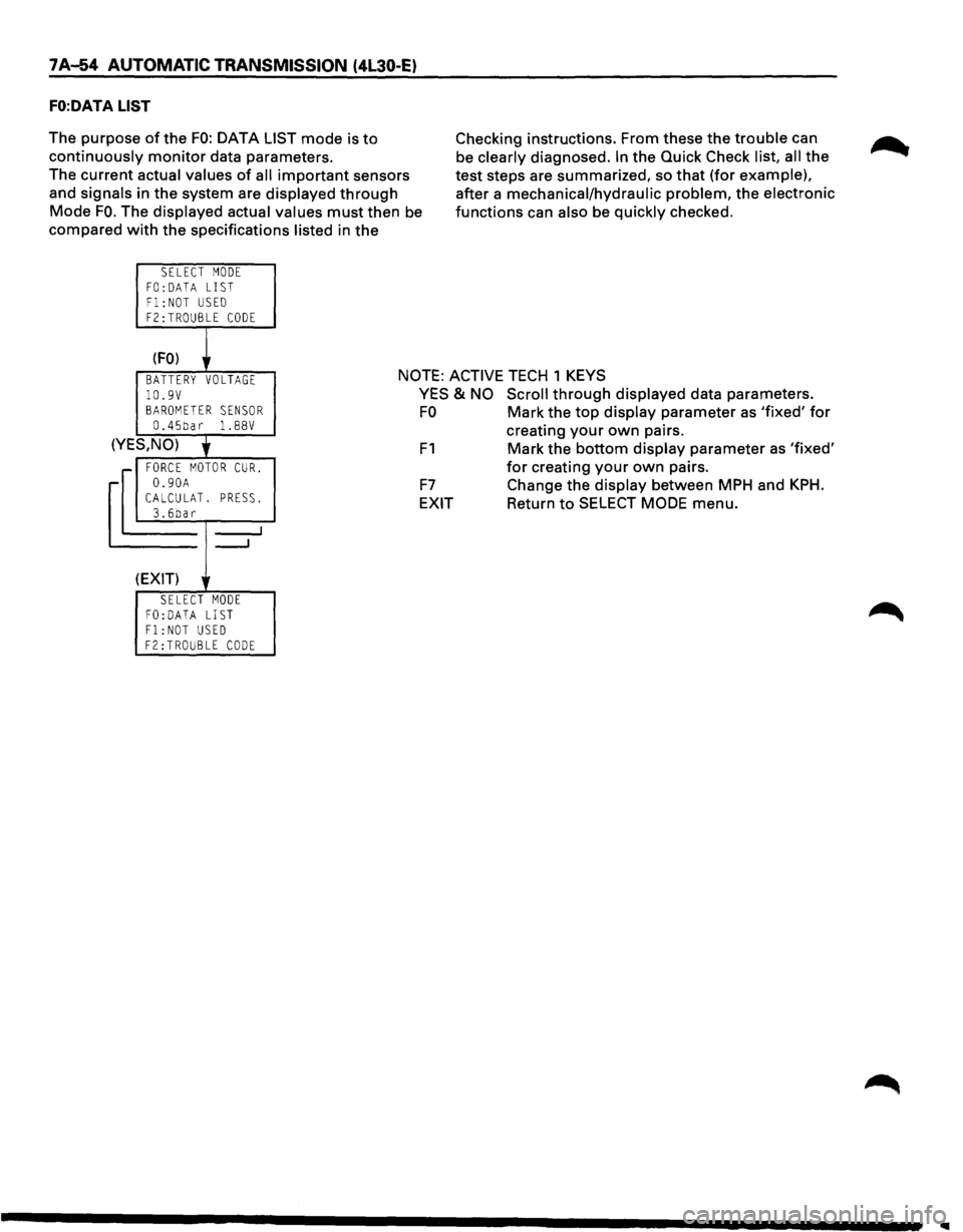
7A-54 AUTOMATIC TRANSMISSION (4L30-E)
FO:DATA LIST
The purpose of the FO: DATA LIST mode is to
continuously monitor data parameters.
The current actual values
of all important sensors
and signals in the system are displayed
through
Mode FO. The displayed actual values must then be
compared
with the specifications listed in the
SELECT MODE
FO: DATA LIST Fl:NOT USED F2:TROUBLE CODE
(FO) r
Checking instructions. From these the trouble can
be clearly diagnosed.
In the Quick Check list, all the
test steps are summarized, so
that (for example),
after a mechanical/hydraulic problem, the electronic
functions can also be quickly checked.
BATTERY VOLTAGE NOTE: ACTIVE TECH 1 KEYS
10.9V BAROMETER SENSOR 0.45bar 1. 88V
(YES,NO)
' r FORCE MOTOR CUR.
-0.90A CALCULAT. PRESS. 3.6bar
_....J
---'
(EXIT)
SELECT MODE FO:DATA LIST Fl:NOT USED F2:TROUBLE CODE
YES & NO Scroll through displayed data parameters.
FO Mark the top display parameter as 'fixed' for
F1
F7
EXIT
creating your own pairs.
Mark the bottom display parameter as 'fixed'
for creating your own pairs.
Change the display between MPH and
KPH.
Return to SELECT MODE menu.
Page 929 of 1928
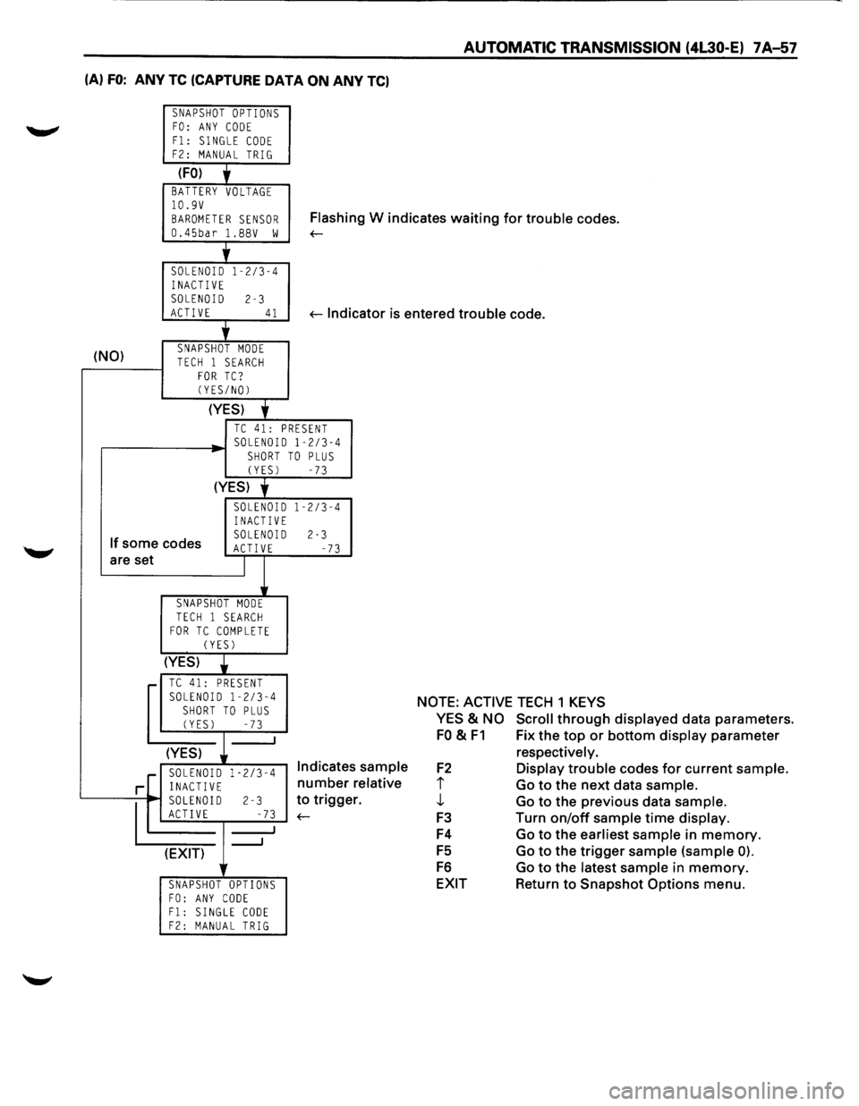
AUTOMATIC TRANSMISSION (4l30·E) 7 A-57
(A) FO: ANY TC (CAPTURE DATA ON ANY TC)
SNAPSHOT OPTIONS FO: ANY CODE
F1: SINGLE CODE F2: MANUAL TRIG
(FO) + BATTERY VOLTAGE 10.9V
BAROMETER SENSOR Flash in g W indicates waiting for trouble codes.
0.45bar l.BBV w ~
'
SOLENOID 1-2/3-4
INACTIVE SOLENOID 2-3 ACTIVE 41 ~lndi cator is entered trouble code.
+
(NO) SNAPSHOT MODE TECH 1 SEARCH FOR TC? (YES/NO)
(YES)
'
TC 41: PRESENT SOLENOID 1-2/3-4 SHORT TO PLUS (YES) -73
(YES) y
SOLENOID 1-2/3-4 INACTIVE
If some codes SOLENOID 2-3 ACT! VE -73 are set I
SNAPSHOT MODE
TECH 1 SEARCH FOR TC COMPLETE (YES)
(YES)
• TC 41: PRESENT SOLENOID 1-2/3-4
SHORT TO PLUS (YES) -73
(YES)
.[ SOLENOID 1-2/3-4 Indicates sample
relative
r. r INACTIVE number
~0
2-3 to trigge
E -73 ~
_J (EXIT) lr
SNAPSHOT OPTIONS FO: ANY CODE F1: SINGLE CODE F2: MANUAL TRIG
NOTE: ACTIVE TECH 1 KEYS
YES
& NO Scroll through displayed data parameters.
FO & F1 Fix the top or bottom display parameter
F2
i j,
F3
F4
FS
F6
EXIT respectively.
Display trouble
codes for current sample.
Go to the next data sample.
Go to the previous data sample.
Turn on/off sample time display.
Go to the earliest sample in memory.
Go to the trigger sample (sample 0).
Go to the latest sample in memory.
Return to Snapshot Options menu.