mirror ISUZU TROOPER 1995 Owner's Manual
[x] Cancel search | Manufacturer: ISUZU, Model Year: 1995, Model line: TROOPER, Model: ISUZU TROOPER 1995Pages: 1928
Page 1457 of 1928
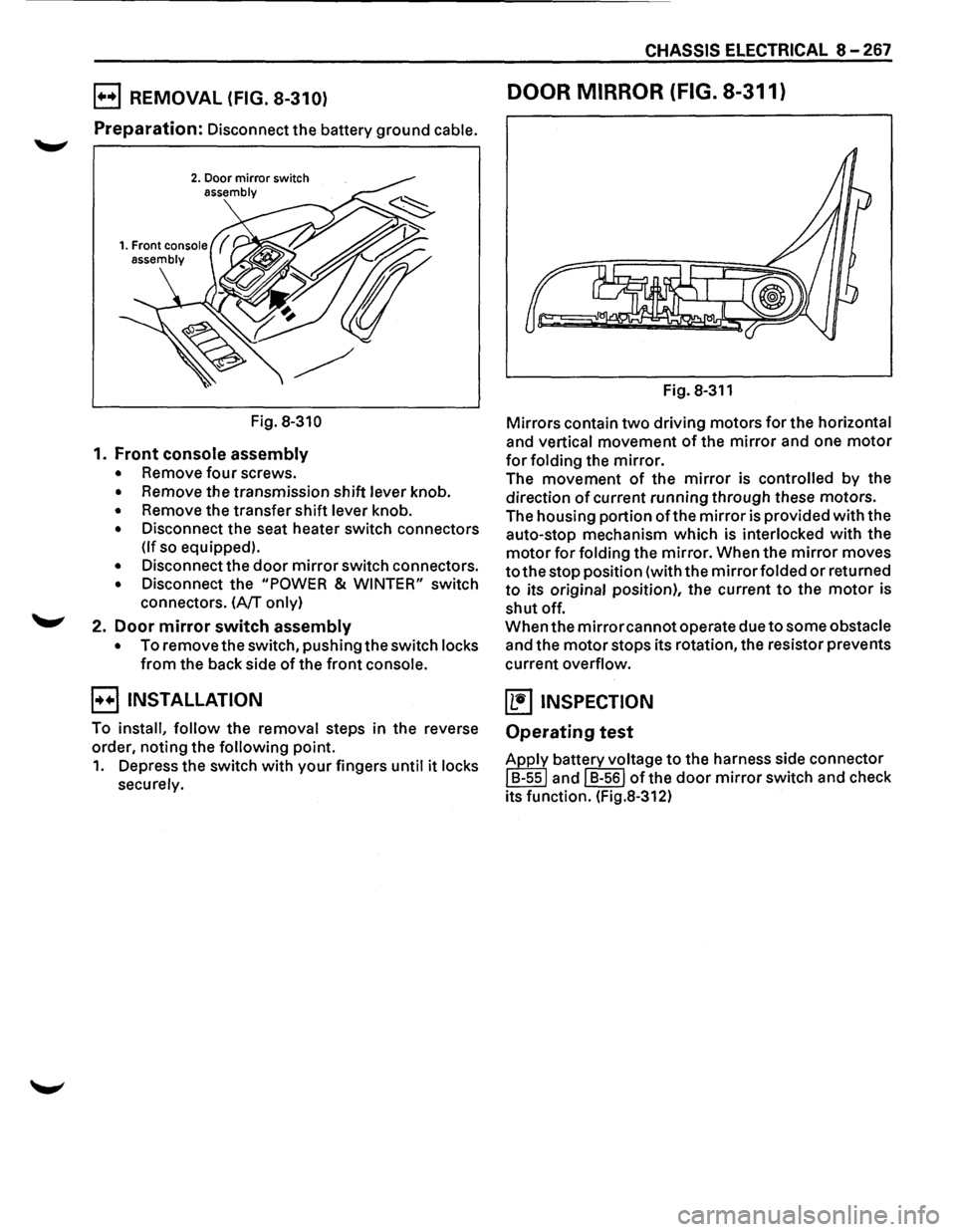
E) REMOVAL (FIG. 8-310)
Preparation: Disconnect the battery ground cable.
2. Door mirror switch assembly
Fig. 8-310
1. Front console assembly
• Remove four screws.
• Remove the transmission shift lever knob.
• Remove the transfer shift lever knob.
• Disconnect the seat heater switch connectors
(If so equipped).
• Disconnect the door mirror switch connectors.
• Disconnect the "POWER & WINTER" switch
connectors.
(A/T only)
2. Door mirror switch assembly
• To remove the switch, pushing the switch locks
from the back side of the front console.
B INSTALLATION
To install, follow the removal steps in the reverse
order, noting the
following point.
1. Depress the switch with your fingers until it locks
securely.
CHASSIS ELECTRICAL 8-267
DOOR MIRROR (FIG. 8-311)
Fig. 8-311
Mirrors contain two driving motors for the horizontal
and vertical movement of the mirror and one motor
for folding the mirror.
The movement of the mirror is controlled by the
direction
of current running through these motors.
The housing portion
ofthe mirror is provided with the
auto-stop mechanism which is
interlocked with the
motor for folding the mirror. When the mirror moves
to the stop position (with the mirror folded or returned
to its original position), the current to the motor is
shut off.
When the
mirror cannot operate due to some obstacle
and the motor stops its rotation, the resistor prevents
current
overflow.
~ INSPECTION
Operating test
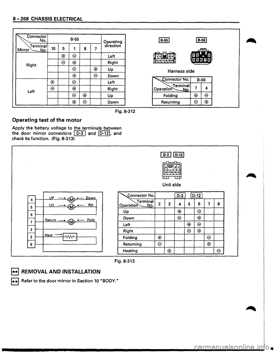
Apply battery voltage to the harness side connector
I B-ssl and I B-561 of the door mirror switch and check
its function. (Fig.8-312)
Page 1458 of 1928
8-268 CHASSIS ELECTRICAL
l~t'
B-55 No.
Operating
ina
I 10 5 1 8 direction
Ho. 7
c±l e Left
e c±l Right
Right
e c±l Up
c±l e Down
c±l e Left
Left
e c±l Right
e c±l Up
<±> e Down
Fig. 8-312
Operating test of the motor
Apply the battery voltage to the terminals between
the
door mirror connectors ~ and ID-121, and
check its function. (Fig. 8-313)
I B-ssl I B-561
•
• ,...., s.:::L -=--
~it! I]&ISI7111t11ol:l 8
Harness side
~nnector No. B-56
~erminal Ope rat o Nn. 7 4
Folding <±> e
Returning e <±>
~ ID-121
_.....,_ .r-1
m 4
~ L..U.
Unit side
......--UP -oown ~onnector No . I D-31 I D-121
--M 4 ~~nal 1--LH RH Opera .,No. 2 3 4 5 6 7 5 --M -1---Up <±> e 6 e <±> -Return--Fold Down 7 M --I Left <±> e
2 Right e <±> -Heat --1 .AAA I 3 I v v I Folding c±l e -8 Returning e c±l L...-Heating <±>
Fig. 8-313
EJ REMOVAl AND INSTAllATION
1++1 Refer to the door mirror in Section 10 "BODY."
8
e
•
Page 1466 of 1928
8-276 CHASSIS ELECTRICAL
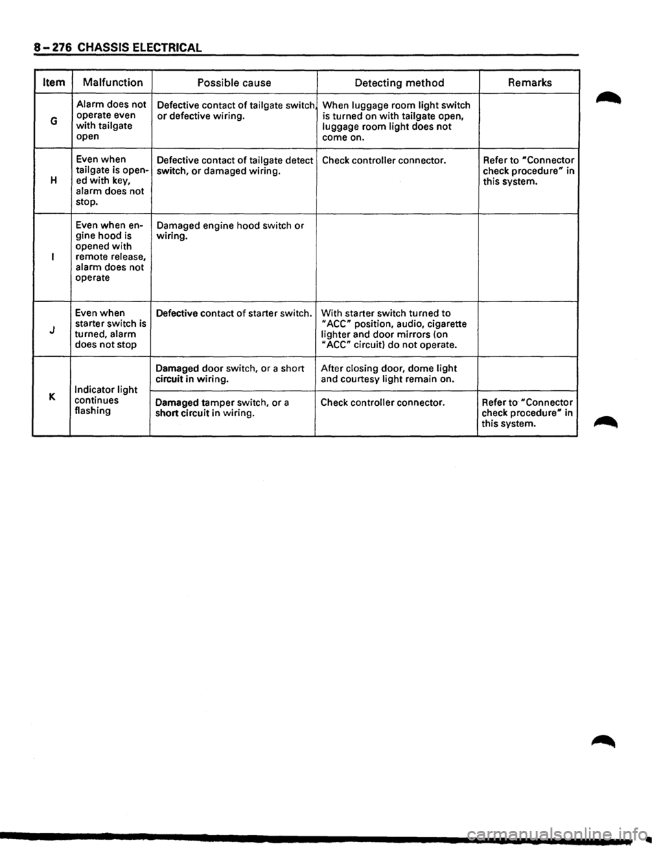
Item Malfunction
Possible cause
Detecting method Remarks
Alarm
does not
Defective contact of tailgate switch When luggage room light switch
G operate even or defective wiring. is turned on with tailgate open, with tailgate
luggage room light does not open
come on.
Even when
Defective contact
of tailgate detect Check controller connector. Refer to "Connector tailgate is open-
switch, or damaged wiring.
check procedure" in H ed with key, this system.
alarm does not
stop.
Even when en-
Damaged engine hood switch or gine hood is wiring.
opened with
I remote release,
alarm does not
operate
Even when
Defective contact
of starter switch. With starter switch turned to
J starter switch is II ACC" position, audio, cigarette
turned, alarm
lighter and door mirrors (on
does not stop
II ACC" circuit) do not operate.
Damaged
door switch, or a short After closing door, dome light
circuit in wiring. and courtesy light remain on.
K Indicator light
continues Damaged tamper switch, or a
Check controller connector. Refer to "Connector flashing
short circuit in wiring. check
procedure" in
this system.
..
Page 1759 of 1928
BODY 10-1
SECTION 10
BODY
\V CAUTION : When fasteners are removed, always reinstall them at the same location from which they
were removed. If a fastener needs to be replaced, use the correct part number fastener for
that application. If the correct part number fastener is not available, a fastener of equal size
and strength (or stronger)
may be used. Fasteners must be used when installing fasteners
that require it. If the above conditions are not followed, parts of system damage could result.
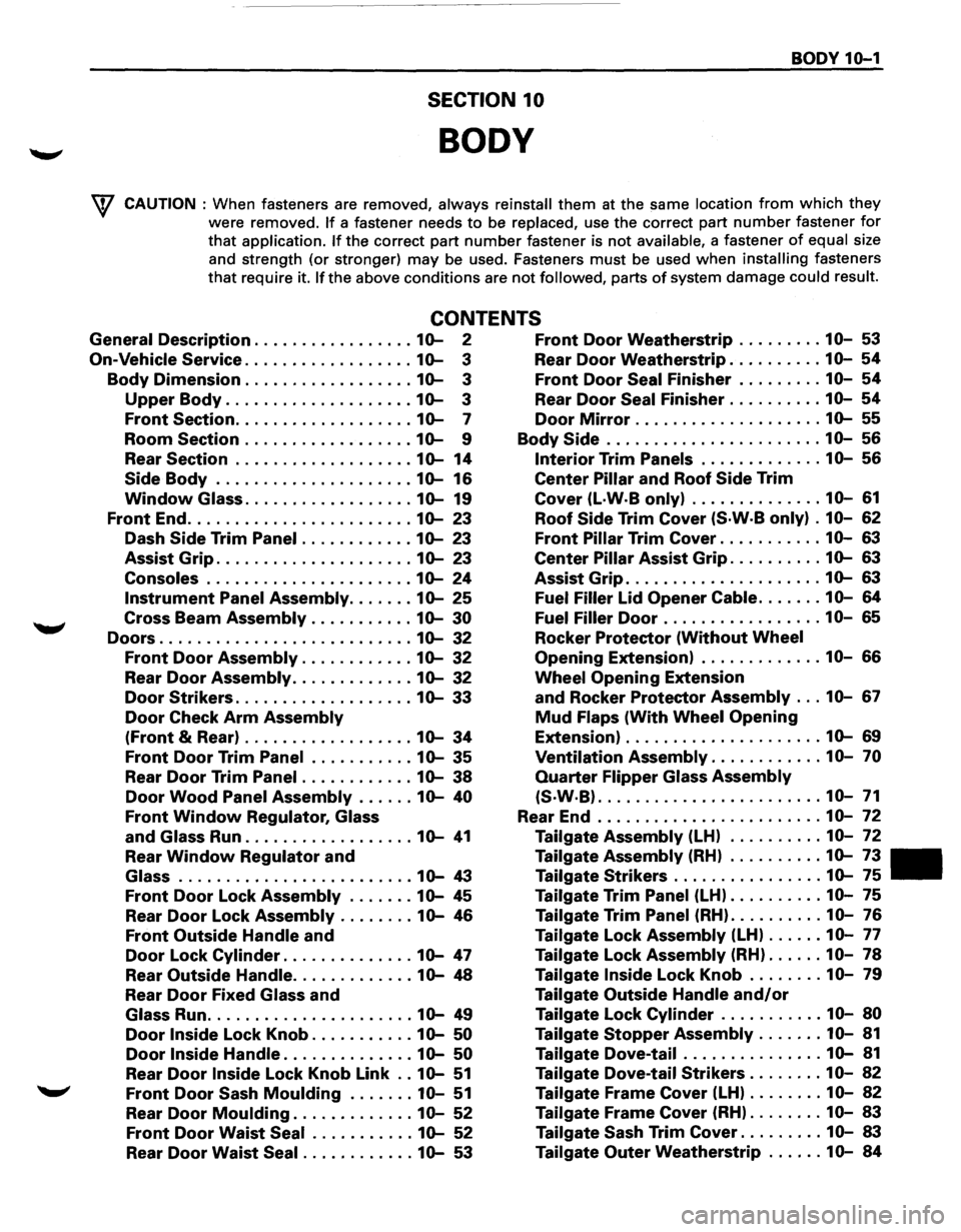
CONTENTS
General Description ................. 10-2 Front Door Weatherstrip ......... 10-53
On-Vehicle Service .................. 10-3 Rear Door Weatherstrip .......... 10-54
Body Dimension .................. 10-3 Front Door Seal Finisher ......... 10-54
Upper Body .................... 10-3 Rear Door Seal Finisher .......... 10-54
Front Section ................... 10-7 Door Mirror .................... 10-55
Room Section .................. 10-9 Body Side ....................... 10-56
Rear Section ................... 10-14 Interior Trim Panels ............. 10-56
Side Body ..................... 10-16 Center Pillar and Roof Side Trim
Window Glass .................. 10-19 Cover (L·W·B only) .............. 10-61
Front End ........................ 10-23 Roof Side Trim Cover (S·W·B only) . 10-62
Dash Side Trim Panel ............ 10-23 Front Pillar Trim Cover ........... 10-63
Assist Grip ..................... 10-23 Center Pillar Assist Grip .......... 10-63
Consoles ...................... 10-24 Assist Grip ..................... 10-63
Instrument Panel Assembly ....... 10-25 Fuel Filler lid Opener Cable ....... 10-64
Cross Beam Assembly ........... 10-30 Fuel Filler Door ................. 10-65
Doors ........................... 10-32 Rocker Protector (Without Wheel
Front Door Assembly ............ 10-32 Opening Extension) ............. 10-66
Rear Door Assembly ............. 10-32 Wheel Opening Extension
Door Strikers ................... 10-33 and Rocker Protector Assembly ... 10-67
Door Check Arm Assembly Mud Flaps (With Wheel Opening
(Front & Rear) .................. 10-34 Extension) ..................... 10-69
Front Door Trim Panel ........... 10-35 Ventilation Assembly ............ 10-70
Rear Door Trim Panel ............ 10-38 Quarter Flipper Glass Assembly
Door Wood Panel Assembly ...... 10-40 (S·W·B) ........................ 10-71
Front Window Regulator, Glass Rear End ........................ 10-72
and Glass Run .................. 10-41 Tailgate Assembly (LH) .......... 10-72
Rear Window Regulator and Tailgate Assembly (RH) .......... 10-73
Glass ......................... 10-43 Tailgate Strikers ................ 10-75
Front Door Lock Assembly ....... 10-45 Tailgate Trim Panel (LH) .......... 10-75
Rear Door Lock Assembly ........ 10-46 Tailgate Trim Panel (RH) .......... 10-76
Front Outside Handle and Tailgate Lock Assembly (LH) ...... 10-77
Door Lock Cylinder .............. 10-47 Tailgate Lock Assembly (RH) ...... 10-78
Rear Outside Handle ............. 10-48 Tailgate Inside Lock Knob ........ 10-79
Rear Door Fixed Glass and Tailgate Outside Handle and/or
Glass Run ...................... 10-49 Tailgate Lock Cylinder ........... 10-80
Door Inside Lock Knob ........... 10-50 Tailgate Stopper Assembly ....... 10-81
Door Inside Handle .............. 10-50 Tailgate Dove-tail ............... 10-81
Rear Door Inside Lock Knob Link .. 10-51 Tailgate Dove-tail Strikers ........ 10-82
Front Door Sash Moulding ....... 10-51 Tailgate Frame Cover (LH) ........ 10-82
Rear Door Moulding ............. 10-52 Tailgate Frame Cover (RH) ........ 10-83
Front Door Waist Seal ........... 10-52 Tailgate Sash Trim Cover ......... 10-83
Rear Door Waist Seal ............ 10-53 Tailgate Outer Weatherstrip ...... 10-84
Page 1793 of 1928
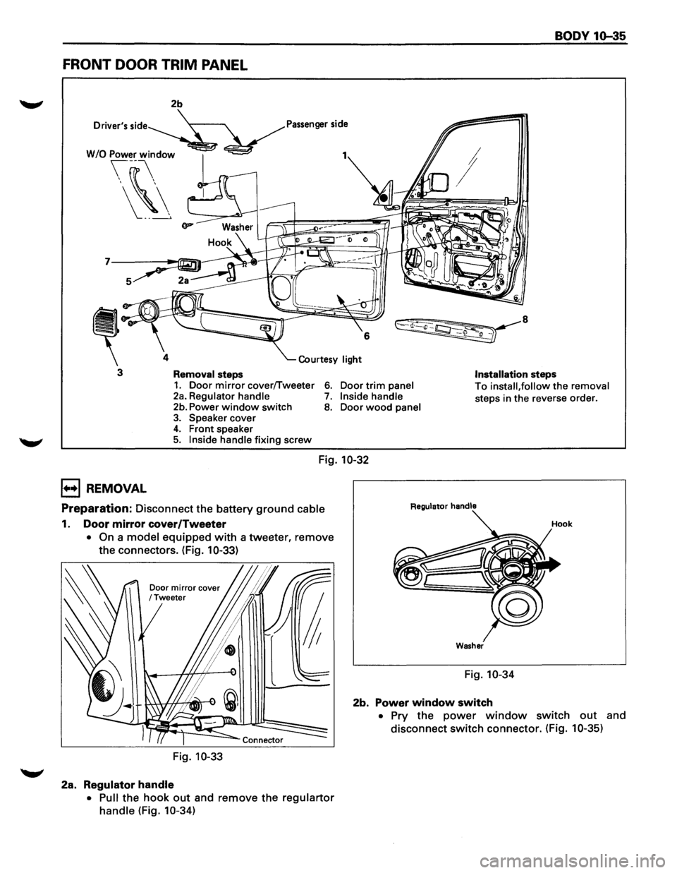
BODY 1Q-35
FRONT DOOR TRIM PANEL
2b
Driver's
side Passenger side
7
4
3 Removal steps Installation steps 1. Door mirror cover/Tweeter 2a. Regulator handle 6. Door trim panel To install, follow the removal
steps in the reverse order. 7. Inside handle 2b. Power window switch 8. Door wood panel 3. Speaker cover 4. Front speaker 5. Inside handle fixing screw
Fig. 10-32
l++l REMOVAL
Preparation: Disconnect the battery ground cable
1. Door mirror cover/Tweeter
• On a model equipped with a tweeter, remove
the connectors. (Fig.
10-33)
Door mirror cover /Tweeter
Fig. 10-33
2a. Regulator handle
• Pull the hook out and remove the regulartor
handle (Fig. 10-34)
Regulator handle
Washer
Fig. 10-34
2b. Power window switch
• Pry the power window switch out and
disconnect
switch connector. (Fig. 10-35)
Page 1810 of 1928
10-52 BODY
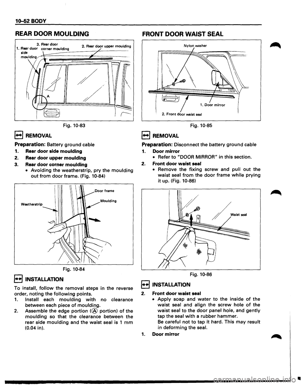
REAR DOOR MOULDING
2. Rear door upper moulding
1••1 REMOVAL
/
/
/
Fig. 10-83
Preparation: Battery ground cable
1. Rear door side moulding
2. Rear door upper moulding
3. Rear door corner moulding
/
• Avoiding the weatherstrip, pry the moulding
out from door frame. (Fig. 10-84)
Weatherstrip
Fig. 10-84
I••! INSTALLATION
To install, follow the removal steps in the reverse
order,
noting the following points.
1. Install each moulding with no clearance
between each piece of moulding.
2. Assemble the edge portion (@ portion) of the
moulding so that the clearance between the
rear side
moulding and the waist seal is 1 mm
(0.04 in).
FRONT DOOR WAIST SEAL
Nylon washer
2. Front door waist seal
Fig. 10-85
1••1 REMOVAL
Preparation: Disconnect the battery ground cable
1. Door mirror
• Refer to "DOOR MIRROR" in this section.
2. Front door waist seal
• Remove the fixing screw and pull out the
waist seal from the door frame while prying
it up. (Fig. 10-86)
Fig. 10-86
I••! INSTALLATION
2. Front door waist seal
~., ..... ,
• Apply soap and water to the inside of the
waist
seal and align the screw hole of the
waist seal to the door panel hole, and gently
tap the seal with a rubber hammer.
Be careful not to tap it hard. This may result
in deforming the seal.
1. Door mirror
•
Page 1813 of 1928
1••1 REMOVAL
Preparation: Battery ground cable
1. Rear door sill plate and luggage side lower
cover
2. Rear
door seal finisher
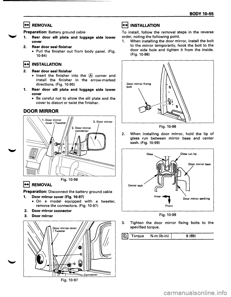
• Pull the finisher out from body panel. (Fig.
10-94)
I++IINSTALLATION
2. Rear door seal finisher
• Insert the finisher into the @ corner and
install the finisher in the arrow-marked
directions. (Fig.
10-95)
1. Rear door sill plate and luggage side lower
cover
• Be careful not to allow the sill plate and the
cover
to distort or twist the finisher.
DOOR MIRROR
3. Door mirror
1+•1 REMOVAL
Fig. 10-96
Preparation: Disconnect the battery ground cable
1. Door mirror cover (Fig. 10-97)
• On a model equipped with a tweeter,
remove
the connectors. (Fig. 10-97)
2. Door mirror connector
3. Door mirror
Fig. 10-97
BODY 10-55
I++IINSTALLATION
To install, follow the removal steps in the reverse
order,
noting the following point.
1. When installing the door mirror, install the bolt
to the mirror temporarily, hook the bolt to the
door side hole and tighten it from the inside.
(Fig.
10-98)
Door mirror fixing bolt
Fig. 10-98
2. When installing door mirror, hold the lip of
glass run between mirror base and center
sash. (Fig.
10-99)
Glass
Center sash
Inner,
Front
Fig. 10-99
Glass run lip
Door mirror packing
3. Tighten the door mirror fixing bolts to the
specified torque.
~~~ Torque N·m Ob·hl) 8 (69)
Page 1869 of 1928
BODY 10-111
ROOF
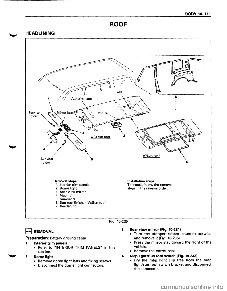
HEADLINING
~---~~I
~r CUp ''-. _ __j
5 1 Adh.,;,;, tap• . T
1
W /0 sun roof 2
Sunvisor
holder 5
Removal steps 1. Interior trim panels 2. Dome light 3. Rear view mirror 4. Map light 5. Sunvisors 6. Sun roof finisher (W/Sun roof) 7. Headlining W/Sun
roof
Installation steps To install, follow the removal steps
in the reverse order. 6
Fig. 10-230
1••1 REMOVAL
Preparation: Battery ground cable
1. Interior trim panels
•
Refer to "INTERIOR TRIM PANELS" in this
section.
2. Dome light
• Remove dome light lens and fixing screws.
• Disconnect the dome light connectors.
3. Rear view mirror (Fig. 10-231)
• Turn the stopper rubber counterclockwise
and remove
it (Fig. 10-235).
• Press the mirror stay toward the front of the
vehicle.
•
Remove the mirror base.
4. Map light/Sun roof switch (Fig. 10-232)
• Pry the map light clip free from the map
light/sun roof switch bracket and disconnect
the connector.