oil type ISUZU TROOPER 1995 Owner's Manual
[x] Cancel search | Manufacturer: ISUZU, Model Year: 1995, Model line: TROOPER, Model: ISUZU TROOPER 1995Pages: 1928
Page 630 of 1928
68 - 2 ENGINE COOLING
The cooling system is a pressurized Engine Coolant
(EC) forced circulation type which consists of water
pump, thermostat cooling fan, radiator and other
components. The automatic transmission fluid is
cooled by the EC in radiator.
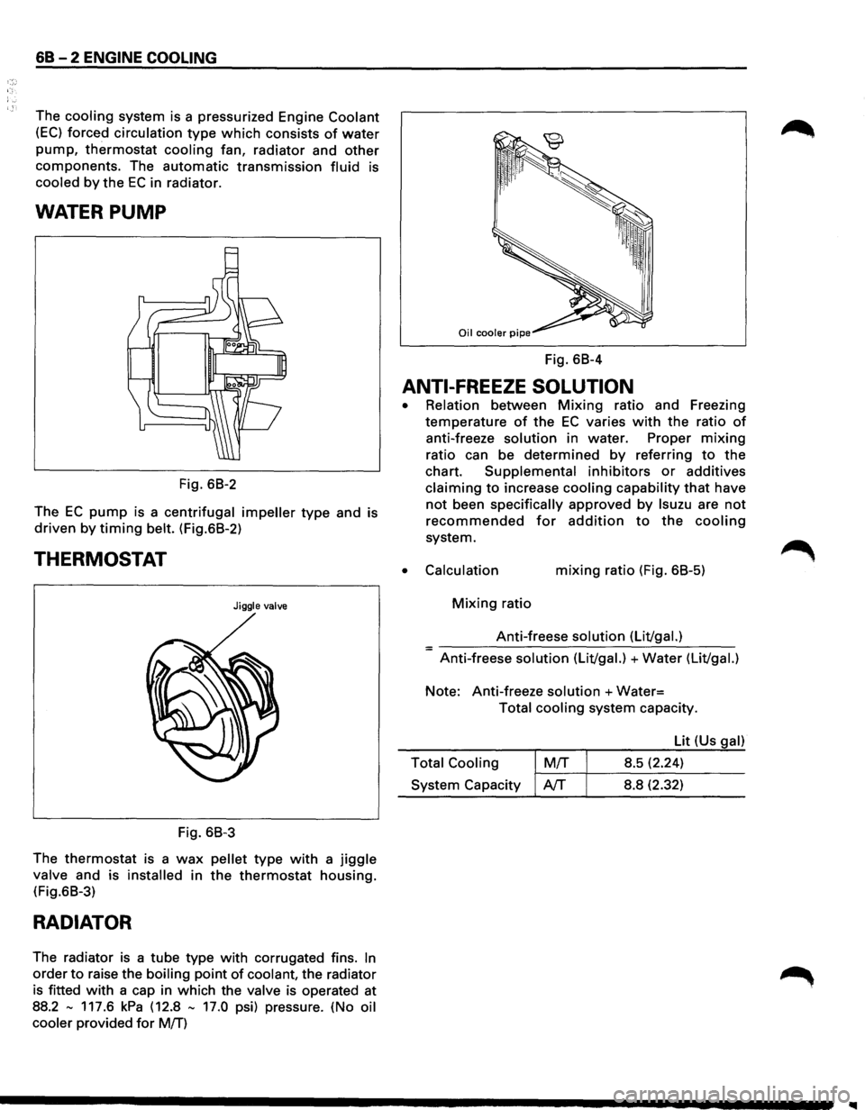
WATER PUMP
Fig. 68-2
The
EC pump is a centrifugal impeller type and is
driven by timing belt. (Fig.68-2)
THERMOSTAT
Jiggle valve
Fig. 68-3
The
thermostat is a wax pellet type with a jiggle
valve and is installed in the thermostat housing.
(Fig.68-3)
RADIATOR
The radiator is a tube type with corrugated fins. In
order to raise the boiling point of coolant, the radiator
is fitted
with a cap in which the valve is operated at
88.2
-117.6 kPa (12.8 - 17.0 psi) pressure. (No oil
cooler
provided for M!f)
Fig. 68-4
ANTI-FREEZE SOLUTION
•
•
Relation between Mixing ratio and Freezing
temperature
of the EC varies with the ratio of
anti-freeze solution in water. Proper mixing
ratio can be determined by referring to the
chart. Supplemental inhibitors or additives
claiming to increase cooling capability that have
not been specifically approved by lsuzu are not
recommended for addition to the cooling
system.
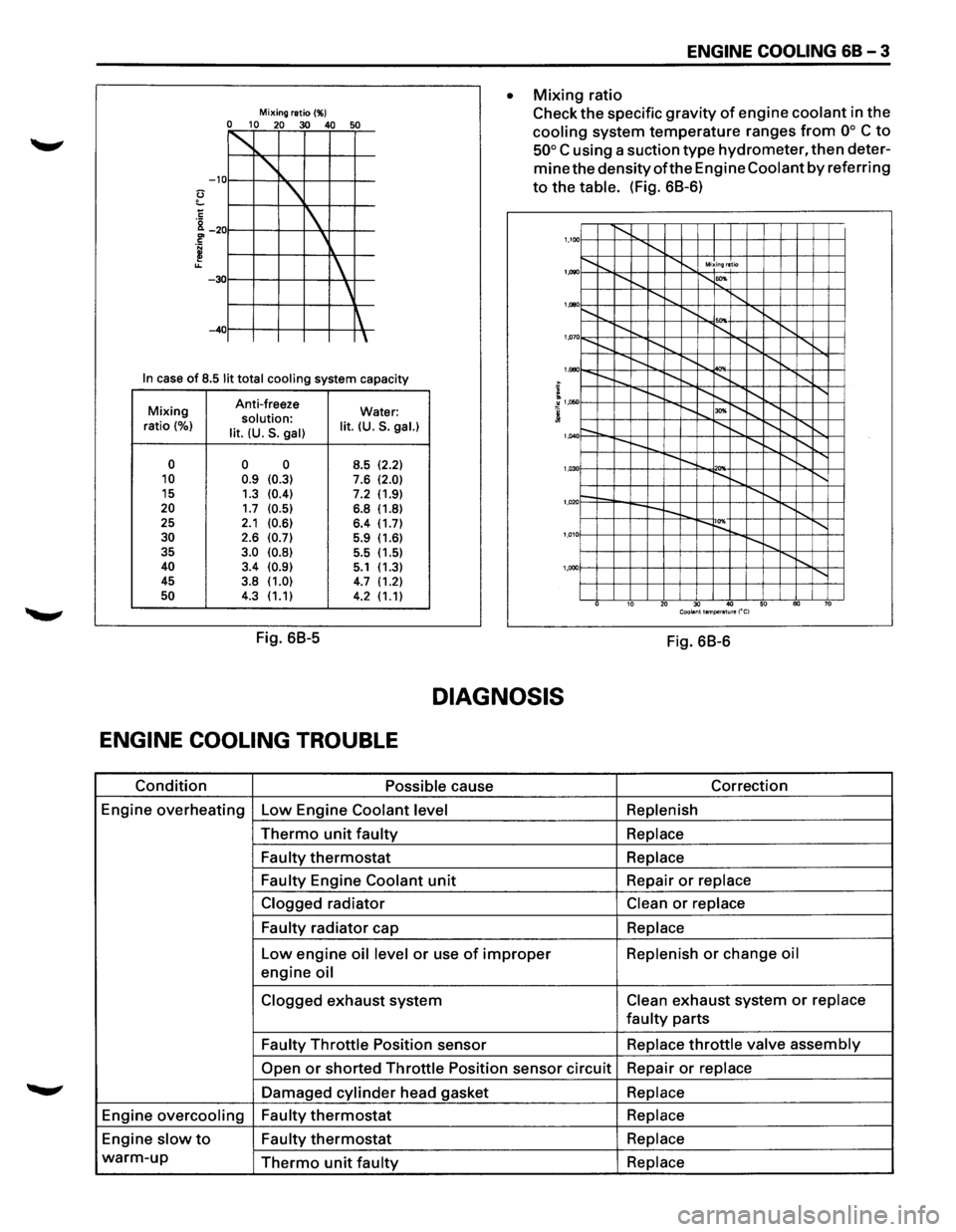
Calculation mixing ratio (Fig. 68-5)
Mixing ratio
Anti-freese
solution (Lit/gal.) =-----------------Anti-freese solution (Lit/gal.) +Water (Lit/gal.)
Note: Anti-freeze solution +Water=
Total cooling system capacity.
Lit (Us
gal)
Total Cooling
M!f 8.5 (2.24) ~-~~--------System Capacity AfT 8.8 (2.32)
Page 631 of 1928
Mixing ratio(%) 0 10 20 30 40 50
~
' -10
'
1
' -30
~ -40
In case of 8.5 lit total cooling system capacity
Mixing Anti-freeze
Water: solution: ratio (%) lit. (U.S. gal) lit. (U.S. gal.)
0 0 0
8.5 (2.2) 10 0.9 (0.3) 7.6 (2.0) 15
1.3 (0.4) 7.2 (1.9) 20 1.7 (0.5) 6.8 (1.8)
25 2.1 (0.6) 6.4 (1.7) 30 2.6 (0.7) 5.9 (1.6)
35 3.0 (0.8) 5.5
(1.5) 40 3.4 (0.9) 5.1 (1.3)
45 3.8 (1.0) 4.7 (1.2) 50 4.3 (1.1)
4.2 (1.1)
Fig. 68-5
ENGINE COOLING 68-3
• Mixing ratio
Check
the specific gravity of engine coolant in the
cooling system temperature ranges from oo C to
50° C using a suction type hydrometer, then deter
mine the densityofthe Engine Coolant by referring
to the table. (Fig. 68-6)
1,100 1'-........ ........ ...... .............. Mixing ratio
~"""--r-... 1'-""' 1,1)90
........ ...... ........ ........ .......... '
1,000
'"" 1,07 o......_ 1'-........ I'-.......... I"-........ .......
I"-........ ..........
................. I"-........
'
1,080
....... I"-........ ~ ........ ......
........ "'" ~"""--r--..... 1,050
r-. ........ ~ .......... ......
---
........ ........ 1,040
r-.... !'--.. 1'-0 '"" ~"""--1'-.... ........ 1,03
1--....... ........ r--~ ........
'
1,020
....... ~ 1'-0 ~"""---.... 1,01
...... ,
'
1,000
10 20 30 40 50 60 70 Coolant temperature ("C)
Fig. 68-6
DIAGNOSIS
ENGINE COOLING TROUBLE
Condition Possible cause Correction
Engine
overheating Low Engine Coolant level Replenish
Thermo unit faulty Replace
Faulty
thermostat Replace
Faulty
Engine Coolant unit Repair or replace
Clogged
radiator Clean or replace
Faulty
radiator cap Replace
Low engine oil level or use of improper Replenish or change oil
engine oil
Clogged exhaust system Clean exhaust system or replace
faulty parts
Faulty Throttle Position sensor Replace throttle valve assembly
Open or shorted Throttle Position sensor circuit Repair or replace
Damaged cylinder head gasket Replace
Engine overcooling Faulty thermostat Replace
Engine slow to Faulty thermostat Replace
warm-up Thermo unit faulty Replace
Page 638 of 1928
68 -10 ENGINE COOLING
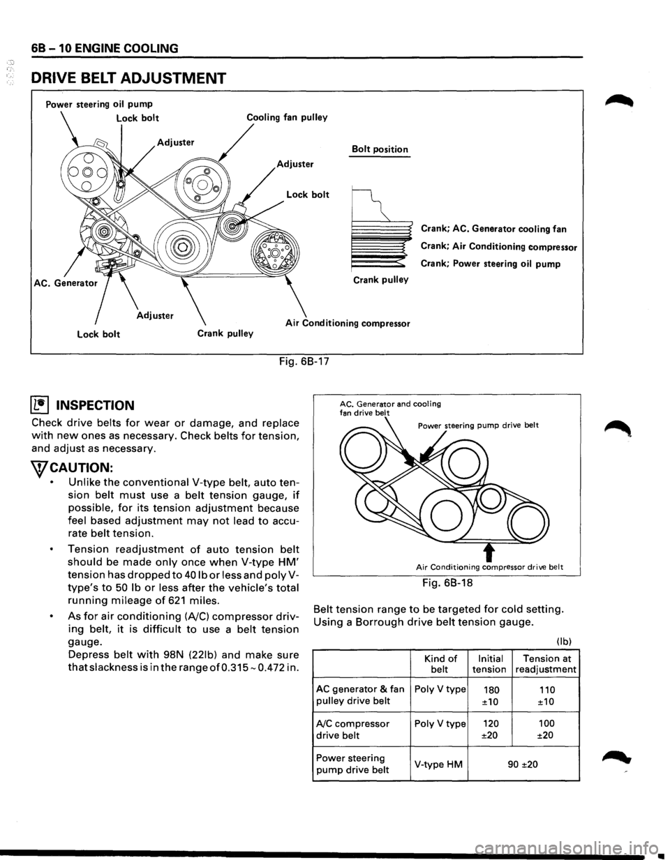
DRIVE BELT ADJUSTMENT
Power steering oil pump
Lock bolt
Bolt position
Adjuster
Crank
pulley
Crank; AC. Generator cooling fan
Crank;
Air Conditioning compressor
Crank; Power steering
oil pump
Air Conditioning compressor
Lock bolt Crank pulley
Fig. 68-17
(b!] INSPECTION
Check drive belts for wear or damage, and replace
with new ones as necessary. Check belts for tension,
and
adjust as necessary.
WCAUTION:
• Unlike the conventional V-type belt, auto ten
sion
belt must use a belt tension gauge, if
possible, for its tension adjustment because
feel based adjustment may not lead to accu
rate
belt tension.
Tension
readjustment of auto tension belt
should be made only once when V-type HM'
tension has dropped to 40 lb or less and polyV
type's to 50 lb or less after the vehicle's total
running mileage of 621 miles.
As for air conditioning (A/C) compressor driv
ing belt, it is difficult to use a belt tension
gauge.
Depress
belt with 98N (221b) and make sure
that slackness is in the range of0.315-0.472 in.
AC. Generator and cooling fan drive belt
Air Conditioning compressor drive belt
Fig. 68-18
Belt tension range to be targeted for cold setting.
Using a
Borrough drive belt tension gauge.
(I b)
Kind of Initial Tension at belt tension readjustment
AC generator & fan Poly V type 180 110 pulley drive belt ±10
±10
A/C compressor Poly V type 120
100
drive belt ±20
±20
Power steering
V-type HM 90 ±20 pump drive belt
•
Page 659 of 1928
CRANKING SYSTEM 6D2 - 1
SECTION 602
CRANKING SYSTEM
CONTENTS
General Description ....................... .
Diagnosis
.................................... .
On-Vehicle Service ........................ . 6D2-1
6D2-3
6D2-8 Unit
Repair.................................... 6D2-9
Main Data and Specifications
............ 6D2-17
Torque Specifications
...................... 6D2-18
GENERAL DESCRIPTION
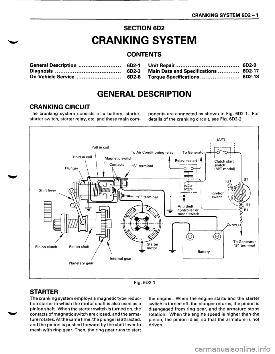
CRANKING CIRCUIT
The cranking system consists of a battery, starter,
starter switch, starter relay, etc. and these main com-
Pull in coil
Hold
in coil
Plunger
Shift lever
Pinion clutch
Internal
gear
Planetary gear
ponents are connected as shown in Fig. 602-1. For
details of the cranking circuit, see Fig. 602-2.
Anti theft controller or mode switch
Battery
(AfT} '-------------. ' '
To Generator "B" terminal
Fig. 602-1
STARTER
The cranking system employs a magnetic type reduc
tion starter in which the motor shaft is also used as a
pinion shaft. When the starter switch is turned on, the
contacts of magnetic switch are closed, and the arma
ture rotates. At the same time, the plunger is attracted,
and the pinion is pushed forward by the shift lever to
mesh with ring gear. Then, the ring gear runs to start
the engine. When the engine starts and the starter
switch is turned off, the plunger returns, the pinion is
disengaged from ring gear, and the armature stops
rotation. When the engine speed is higher than the
pinion, the pinion idles, so that the armature is not
driven.
Page 677 of 1928
CHARGING SYSTEM 6D3-1
SECTION 603
CHARGING SYSTEM
CONTENTS
General Description ....................... .
Diagnosis
.................................... .
On-Vehicle Service ........................ . 6D3-1
6D3-3
6D3-4 Unit
Repair . . .. .. . . . . . . . . . . . . .. . . . . . . . . . . . . . . . 6D3-6
Inspection and Repair . . . . . . . . . . . . . . . . . . 6D3-8
Main Data and Specifications............ 6D3-12
GENERAL DESCRIPTION
The charging system is the IC integral regulator charg
ing system and its main components are connected as
shown in Fig. 6D3-1.
The regulator is a solid state
type and it is mounted
along with the brush holder assembly inside the
generator installed on the rear end cover. The
generator does not require particular mainte
nance such
as voltage adjustment. The rectifier con
nected
to the stator coil has eight diodes to transform
A.C. voltage into D.C. voltage. This D.C. voltage is
connected
to the output terminal of generator. (Fig.
6D3-1)
Page 692 of 1928
604-4 IGNITION SYSTEM
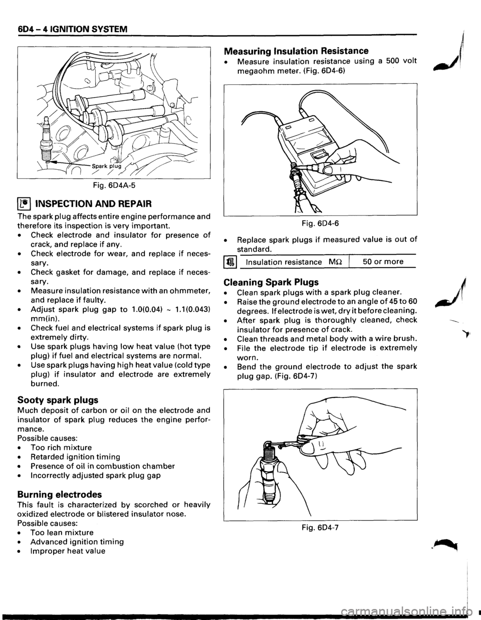
Fig. 604A-5
~ INSPECTION AND REPAIR
The spark plug affects entire engine performance and
therefore its inspection is very important.
• Check electrode and insulator for presence of
crack, and replace if any.
• Check electrode for wear, and replace if neces
sary.
• Check gasket for damage, and replace if neces
sary.
• Measure insulation resistance with an ohmmeter,
and replace if faulty.
• Adjust spark plug gap to 1.0(0.04) -1.1 (0.043)
mm(in).
• Check fuel and electrical systems if spark plug is
extremely dirty.
• Use spark plugs having low heat value (hot type
plug) if fuel and electrical systems are normal.
• Use spark plugs having high heat value (cold type
plug) if insulator and electrode are extremely
burned.
Sooty spark plugs
Much deposit of carbon or oil on the electrode and
insulator of spark plug reduces the engine perfor
mance.
Possible causes:
• Too rich mixture
• Retarded ignition timing
• Presence of oil in combustion chamber
• Incorrectly adjusted spark plug gap
Burning electrodes
This fault is characterized by scorched or heavily
oxidized electrode or blistered insulator nose.
Possible causes:
• Too lean mixture
• Advanced ignition timing
• Improper heat value
Measuring Insulation Resistance
• Measure insulation resistance using a 500 volt
megaohm meter. (Fig. 604-6)
Fig.
604-6
• Replace spark plugs if measured value is out of
standard.
I @!.j Insulation resistance MQ 50 or more
Cleaning Spark Plugs
• Clean spark plugs with a spark plug cleaner.
• Raise the ground electrode to an angle of 45 to 60
degrees. If electrode is wet, dry it before cleaning.
• After spark plug is thoroughly cleaned, check
insulator for presence of crack.
• Clean threads and metal body with a wire brush.
• File the electrode tip if electrode is extremely
worn.
• Bend the ground electrode to adjust the spark
plug gap. (Fig. 604-7)
Fig. 604-7
•
Page 742 of 1928
6E2-46 DRIVEABILITV AND EMISSIONS
CHART A-3
(Page 3 of 3)
ENGINE CRANKS BUT WILL NOT RUN
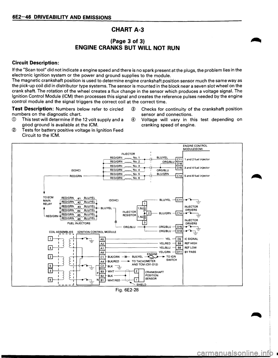
Circuit Description:
If the "Scan tool" did not indicate a engine speed and there is no spark present at the plugs, the problem lies in the
electronic ignition system
or the power and ground supplies to the module.
The magnetic crankshaft position is used to determine engine crankshaft position sensor much the same way as
the pick-up coil did in distributor type systems. The sensor is mounted in the block near a seven slot wheel on the
crank shaft. The rotation
of the wheel creates a flux change in the sensor which produces a voltage signal. The
Ignition Control Module (ICM) then processes this signal and creates the reference pulses needed by the engine
control module and the signal triggers the correct coil at the correct time.
Test Description: Numbers below refer to circled ® Checks for continuity of the crankshaft position
numbers on the diagnostic chart. sensor and connections.
available at the ICM. cranking speed of engine.
® Tests for battery positive voltage in Ignition Feed
Circuit to the
ICM.
TO ECM RED/GRN #1 BLU/YEL MAIN RELAY
tRED/GRN
RED/GRN #2 BLU/YEL
RED/GRN #3 BLU/YEL
RED/GRN '"#4 BLU/YEL RED/GRN #5 BLU/YEL RED/GRN #6 BLU/YEL
FUEL
INJECTORS INJECTOR
RED/GRN RED/GRN RED/GRN
E"'QINE YELJGRN D11 BLK!ORN ----)>--BLK!YEL _____..,-~ TO IGN BLK!RED
-TO TACHOMETER SWITCH BLK --:::J_ AND TCM (C91-D12)
WHT2cl]= :-·-, 2 CRANKSHAFT BLK ~ : POSITION WHT/RED · __ ,' 1 SENSOR
'-;SHIELD
Fig. 6E2-28
ENGINE CONTROL
MODULEIECM)
1 and 2 fuel injector
•
Page 804 of 1928
6E2-1 08 DRIVEABILITV AND EMISSIONS
CHART C-1A
PARK/NEUTRAL POSITION (PNP} SWITCH DIAGNOSIS
(AUTO TRANSMISSION ONL
V}
Circuit Description:
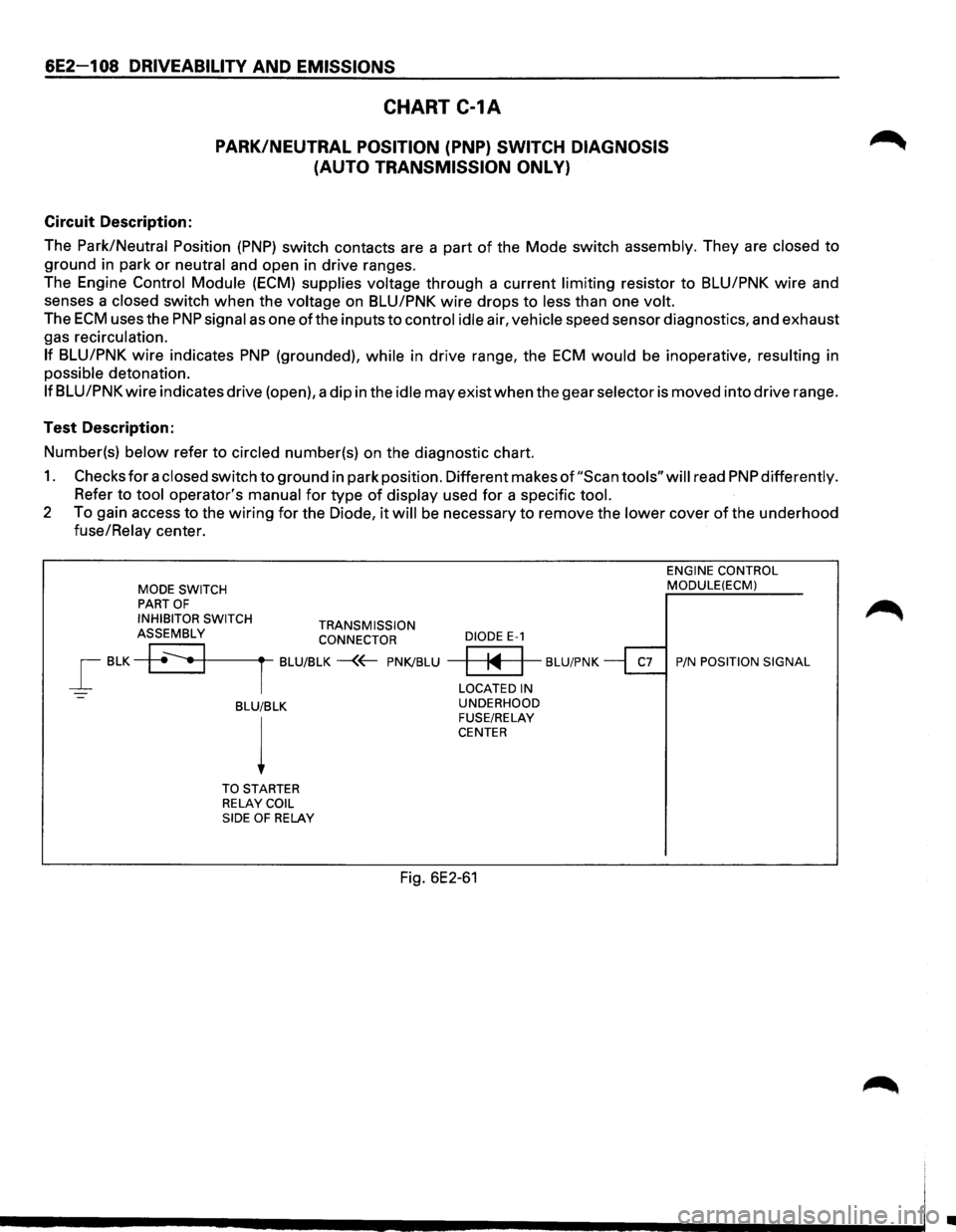
The
Park/Neutral Position (PNP) switch contacts are a part of the Mode switch assembly. They are closed to
ground in park or neutral and open in drive ranges.
The Engine
Control Module (ECM) supplies voltage through a current limiting resistor to BLU/PNK wire and
senses a
closed switch when the voltage on BLU/PNK wire drops to less than one volt.
The ECM uses the PNP signal as one ofthe inputs to control idle air, vehicle speed sensor diagnostics, and exhaust
gas recirculation.
If BLU/PNK wire indicates PNP (grounded), while in drive range, the ECM would be inoperative, resulting in
possible detonation.
If BLU/PNK wire indicates drive (open), a dip in the idle may exist when the gear selector is moved into drive range.
Test Description:
Number(s)
below refer to circled number(s) on the diagnostic chart.
1. Checks for a closed switch to ground in park position. Different makes of "Scan tools" will read PNP differently.
Refer to tool operator's manual for type of display used for a specific tool.
2 To gain access to the wiring for the Diode, it will be necessary to remove the lower cover of the underhood
fuse/Relay center.
MODE SWITCH PART OF
INHIBITOR SWITCH TRANSMISSION ASSEMBLY CONNECTOR
_[ BLK +~•+1-------rt--BLU/BLK -{~ PNK/BLU
-BLU/BLK
l
TO STARTER
RELAY COIL
SIDE OF RELAY
DIODE E-1
ENGINE CONTROL MODULE(ECM)
~ BLU/PNK ~ P/N POSITION SIGNAL
LOCATED IN
UNDERHOOD
FUSE/RELAY
CENTER
Fig. 6E2-61
Ill
Page 838 of 1928
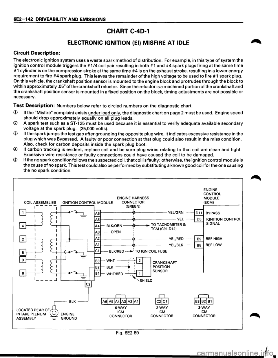
6E2-142 DRIVEABILITY AND EMISSIONS
CHART C-40-1
ELECTRONIC IGNITION (EI) MISFIRE AT IDLE
Circuit Description:
The electronic ignition system uses a waste spark method of distribution. For example, in this type of system the
ignition
control module triggers the #1 /4 coil pair resulting in both #1 and #4 spark plugs firing at the same time
# 1
cylinder is on the compression stroke at the same time #4 is on the exhaust stroke, resulting in a lower energy
requirement
to fire #4 spark plug. This leaves the remainder of the high voltage to be used to fire # 1 spark plug.
On this vehicle, the crankshaft position sensor is mounted to the engine block and protrudes through the block to
within approximately .05" ofthe crankshaft reluctor. Since the reluctor is a machined portion ofthe crankshaft and
the crankshaft position sensor is mounted in a fixed position on the
block, timing adjustments are not possible or
necessary.
Test Description: Numbers below refer to circled numbers on the diagnostic chart.
CD If the "Misfire" complaint exists under load only, the diagnostic chart on page 2 must be used. Engine speed
should drop approximately equally on all plug leads.
® A spark test such as a ST-125 must be used because it is essential to verify adequate available secondary
voltage at the spark plug. (25,000 volts).
@ If the spark jumps the test gap after grounding the opposite plug wire, it indicates excessive resistance in the
plug which was Bypassed. A faulty or poor connection at that plug could also result in the miss condition.
Also, check for carbon deposits inside the spark plug boot.
@ If carbon tracking is evident, replace coil and be sure plug wires relating to that coil are clean and tight.
Excessive
wire resistance or faulty connections could have caused the coil to be damaged.
@ If the no spark condition follows the suspected coil, that coil is faulty; otherwise, the ignition control module is
the cause
of no spark. This test could also be performed by substituting a known good coil for the one causing
the no spark condition.
ENGINE HARNESS
COIL ASSEMBLIES IGNITION CONTROL MODULE CONNECTOR
1-- - - -(GREEN)
~ '--1-1 -+---,
I
:TI
:D
r---------~~----------YE~GRN
~--------~~-------------VEL ' BLKJORN -----4---+-TO TACHOMETER & •
TCM (C91-D12) OPEN ! ' r---------~~----------YE~RED
r-----------<1~----------YEL!BLK ' BLKJRED ___..,TO IGN COIL FUSE
IAsiAsl;rJIA21A 1!
6-WAY ICM
CONNECTOR
Fig. 6E2-89
CRANKSHAFT
POSITION
SENSOR
lc0§,1
2-WAY ICM
CONNECTOR ENGINE
CONTROL
MODULE
(ECM)
BYPASS IGNITION CONTROL
SIGNAL
REF HIGH
REF LOW
IB!IB2I~1I
3-WAY ICM CONNECTOR
Page 840 of 1928
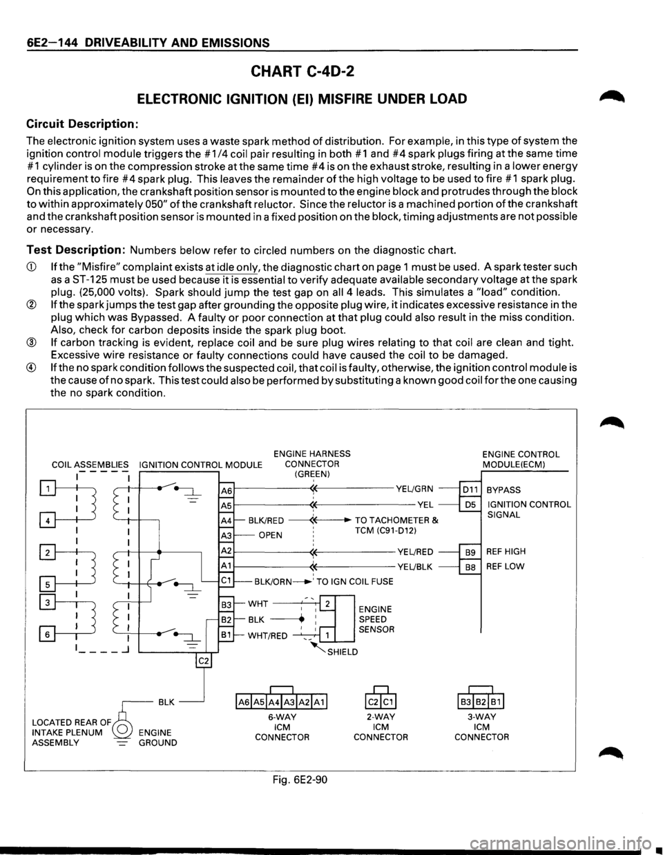
6E2-144 DRIVEABILITY AND EMISSIONS
CHART C-40-2
ELECTRONIC IGNITION (EI) MISFIRE UNDER LOAD
Circuit Description:
The electronic ignition system uses a waste spark method of distribution. For example, in this type of system the
ignition
control module triggers the # 1/4 coil pair resulting in both # 1 and #4 spark plugs firing at the same time
# 1 cylinder is on the compression stroke at the same time #4 is on the exhaust stroke, resulting in a lower energy
requirement
to fire #4 spark plug. This leaves the remainder of the high voltage to be used to fire #1 spark plug.
On this application, the crankshaft position sensor is mounted to the engine block and protrudes through the block
to within approximately 050" of the crankshaft reluctor. Since the reluctor is a machined portion of the crankshaft
and the crankshaft position sensor is mounted in a fixed position on the
block, timing adjustments are not possible
or necessary.
Test Description: Numbers below refer to circled numbers on the diagnostic chart.
CD If the "Misfire" complaint exists at idle only, the diagnostic chart on page 1 must be used. A spark tester such
as a ST-125 must be used because it is essential to verify adequate available secondary voltage at the spark
plug. (25,000 volts). Spark should jump the test gap on all 4 leads. This simulates a "load" condition.
® If the spark jumps the test gap after grounding the opposite plug wire, it indicates excessive resistance in the
plug which was Bypassed. A faulty or poor connection at that plug could also result in the miss condition.
Also, check for carbon deposits inside the spark plug boot.
® If carbon tracking is evident, replace coil and be sure plug wires relating to that coil are clean and tight.
Excessive
wire resistance or faulty connections could have caused the coil to be damaged.
® If the no spark condition follows the suspected coil, that coil is faulty, otherwise, the ignition control module is
the cause
of no spark. This test could also be performed by substituting a known good coil for the one causing
the no spark condition.
COIL ASSEMBLIES IGNITION CONTROL MODULE
ENGINE HARNESS
CONNECTOR
(GREEN) -----
:TI '--+I -l-----,
I
:TI
~
~--------~~-----------YE~GRN
~--------~~--------------VEL ' BLK/RED ------«--TO TACHOMETER &
OPEN ' TCM (C91-D12)
~--------~~-----------YE~RED
1------------((-----------YE~BLK ' BLK/ORN_.' TO IGN COIL FUSE
ENGINE SPEED
1 SENSOR
~SHIELD
IAsiAsii4ibiA21A11
6-WAY ICM
CONNECTOR
Fig. 6E2-90
lcik,l
2-WAY ICM
CONNECTOR ENGINE
CONTROL
MODULE(ECM)
BYPASS
IGNITION CONTROL
SIGNAL
REF HIGH
REF LOW
I
BJIB2I~1I
3-WAY ICM
CONNECTOR
•