oil type ISUZU TROOPER 1995 User Guide
[x] Cancel search | Manufacturer: ISUZU, Model Year: 1995, Model line: TROOPER, Model: ISUZU TROOPER 1995Pages: 1928
Page 173 of 1928
I••IINSTALLATION
9. Knuckle
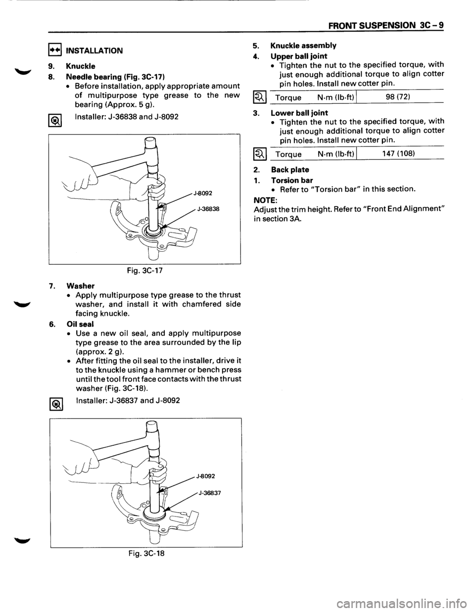
8. Needle bearing (Fig. 3C-17)
• Before installation, apply appropriate amount
of multipurpose type grease to the new
bearing (Approx. 5 g).
1®.1 Installer: J-36838 and J-8092
Fig. 3C-17
7. Washer
• Apply multipurpose type grease to the thrust
washer, and install it with chamfered side
facing
knuckle.
6. Oil seal
• Use a new oil seal, and apply multipurpose
type grease to the area surrounded by the lip
(approx. 2 g).
• After fitting the oil seal to the installer, drive it
to the knuckle using a hammer or bench press
until the tool front face contacts with the thrust
washer (Fig. 3C-18).
Installer:
J-36837 and J-8092
Fig. 3C-18
FRONT SUSPENSION 3C-9
5. Knuckle assembly
4. Upper ball joint
• Tighten the nut to the specified torque, with
just enough additional torque to align cotter
pin holes. Install new cotter pin.
~~~ Torque N·m (lb·ftl I 98 (72)
3. Lower ball joint
• Tighten the nut to the specified torque, with
just enough additional torque to align cotter
pin holes. Install new cotter pin.
~~~ Torque N·m (lb·ftl I 147 (108)
2. Back plate
1. Torsion bar
• Refer to "Torsion bar" in this section.
NOTE:
Adjust the trim height. Refer to "Front End Alignment"
in section 3A.
Page 188 of 1928
30-2 REAR SUSPENSION
GENERAL DESCRIPTION
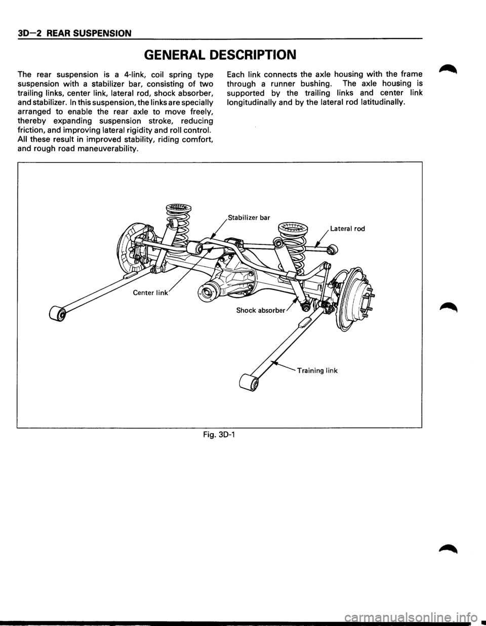
The rear suspension is a 4-link, coil spring type
suspension
with a stabilizer bar, consisting of two
trailing links, center link, lateral rod, shock absorber,
and
stabilizer. In this suspension, the links are specially
arranged to enable the rear axle to move freely,
thereby expanding suspension stroke, reducing
friction, and improving
lateral rigidity and roll control.
All
these result in improved stability, riding comfort,
and rough road
maneuverability.
Each link connects the axle housing with the frame
through a runner bushing. The
axle housing is
supported
by the trailing links and center link
longitudinally
and by the lateral rod latitudinally.
Lateral rod
Training
link
Fig. 30-1
•
Page 198 of 1928
3D -12 REAR SUSPENSION
l+•liNSTALLATION
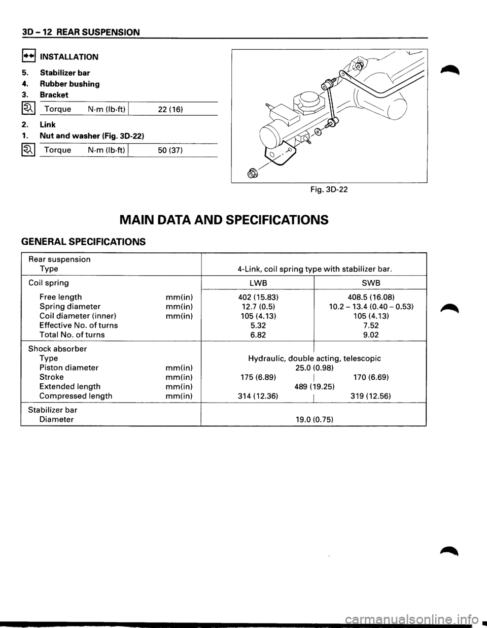
5. Stabilizer bar
4. Rubber bushing
3. Bracket
~~~ Torque N·m (lb.ft) I 22 (16)
2. Link
1. Nut and washer (Fig. 30-22)
~~~ Torque N-m (lb·ft) I 50 (37)
Fig.
30-22
MAIN DATA AND SPECIFICATIONS
GENERAL SPECIFICATIONS
Rear suspension
Type 4-Link, coil spring type with stabilizer bar.
Coil spring LWB SWB
Free
length mm(in) 402 (15.83) 408.5 (16.08)
Spring diameter mm(in) 12.7 (0.5) 10.2-13.4 (0.40-0.53)
Coil diameter (inner) mm(in) 105 (4.13) 105(4.13)
Effective No.
of turns 5.32 7.52
Total No. of turns 6.82 9.02
Shock absorber
Type Hydraulic, double acting, telescopic
Piston diameter mm(in) 25.0
(0.98)
Stroke
mm(in) 175 (6.89) I 170 (6.69)
Extended
length mm(in) 489 (19.25)
Compressed length mm(in) 314 (12.36) I 319 (12.56)
Stabilizer bar
Diameter 19.0 (0.75)
•
Page 243 of 1928
REAR AXLE 48-1
SECTION 48
REAR AXLE
\V CAUTION:
When fasteners are removed, always reinstall them at the same location from which they were removed.
If a fastener needs to be replaced, use the correct part number fastener for that application. If the correct
part number fastener is not available, a fastener of equal size and strength (or stronger) may be used.
Fasteners
that are not reused, and those requiring thread locking compound, will be called out. The
correct
torque values must be used when installing fasteners that require torque. If the above conditions
are not followed, parts or system damage could result.
CONTENTS
General Description . . . . . . . . . . . . . . . . . . . . 48-1
Diagnosis of Rear
Axle Noise . .
. . . . . . . . . . 48-3
On-Vehicle Service ..................... 48-4
Axle Housing . .
. . . . . . . . . . . . . . . . . . . . . 48-4
Axle Shaft . .
. . . . . . . . . . . . . . . . . . . . . . . . 48-7
Pinion
Oil Seal . .
. . . . . . . . . . . . . . . . . . . .
48-10
Differential Assembly
. .
. . . . . . . . . . . . . . 48-11 Unit
Repair . . . . . . . . . . . . . . . . . . . . . . . . . . . 48-13
Differential Assembly . .
. . . . . . . . . . . . . .
48-13 Differential Cage Assembly . . . . . . . . . . . . 48-23
Limited
Slip Differential . .
. . . . . . . . . . . . 48-27
Main Data and Specifications . . . . . . . . . . . . 48-33
General Specifications . .
. . . . . . . . . . . . . . 48-33
Torque Specifications
................ 48-34
Special Tools ......................... 48-35
GENERAL DESCRIPTION
The rear axle assembly is of the semi-floating type in
which the vehicle weight is carried on the axle
housing (Fig. 48-1).
The center
line of the pinion gear is below the center
line of the ring gear (hypoid drive).
All parts necessary to transmit power from the
propeller shaft to the rear wheels are enclosed in a
banjo type axle housing.
The 8.7 inch ring gear rear axle uses a conventional
ring and
pinion gear set to transmit the driving force
of the engine to the rear wheels. This gear set transfers
this driving force at a 90 degree angle from the
propeller shaft to the drive shafts. The
axle shafts
are supported at the wheel end of the
shaft by a roller bearing.
The
pinion gear is supported by two tapered roller
bearings. The pinion depth is set by a shim pack
located between the gear end of the pinion and the
roller bearing that is pressed onto the pinion. The
pinion bearing preload is set by crushing a collapsible
spacer between the bearings in the axle housing.
Page 279 of 1928
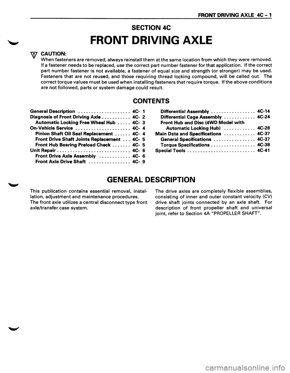
FRONT DRIVING AXLE 4C-1
SECTION 4C
FRONT DRIVING AXLE
'f CAUTION:
When fasteners are removed, always reinstall them at the same location from which they were removed.
If a fastener needs to be replaced, use the correct part number fastener for that application. If the correct
part
number fastener is not available, a fastener of equal size and strength (or stronger) may be used.
Fasteners
that are not reused, and those requiring thread locking compound, will be called out. The
correct
torque values must be used when installing fasteners that require torque. If the above conditions
are not followed, parts or system damage could result.
CONTENTS
General Description . . . . . . . . . . . . . . . . . . . . 4C-1
Diagnosis
of Front Driving Axle . . . . . . . . . . . 4C-2
Automatic Locking Free Wheel Hub . . . . . 4C-3
On-Vehicle Service ..................... 4C- 4
Pinion
Shaft Oil Seal Replacement . . . . . . 4C-4
Front Drive Shaft Joints Replacement . . . 4C-5
Front Hub Bearing Preload Check . . . . . . . 4C-5
Unit Repair . . . . . . . . . . . . . . . . . . . . . . . . . . . . 4C-6
Front Drive Axle Assembly . . . . . . . . . . . . 4C-6
Front Axle Drive Shaft . . . . . . . . . . . . . . . . 4C-9
Differential Assembly ................. 4C-14
Differential Cage Assembly . . . . . . . . . . . . 4C-24
Front Hub and Disc (4WD Model with
Automatic Locking Hub) . . . . . . . . . . . . 4C-28
Main Data and Specifications . . . . . . . . . . . . 4C-37
General Specifications . .
. . . . . . . . . . . . . . 4C-37
Torque Specifications ................. 4C-38
Special Tools .......................... 4C-41
GENERAL DESCRIPTION
This publication contains essential removal, instal
lation,
adjustment and maintenance procedures.
The
front axle utilizes a central disconnect type front
axle/transfer case system. The
drive axles are completely flexible assemblies,
consisting
of inner and outer constant velocity (CV)
drive shaft joints connected by an axle shaft. For
description
of front propeller shaft and universal
joint, refer to Section 4A "PROPELLER SHAFT".
Page 315 of 1928
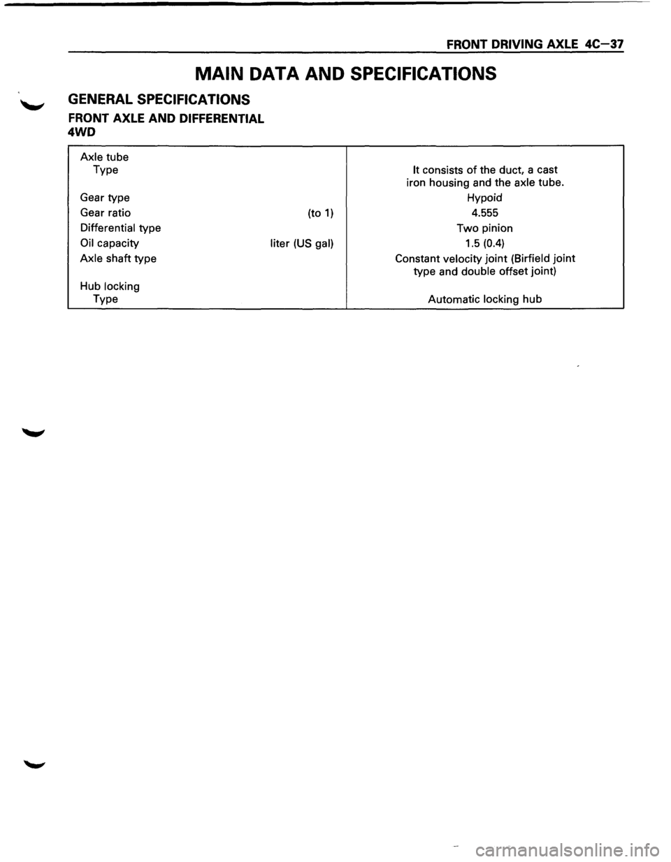
FRONT DRIVING AXLE 4C-37
MAIN DATA AND SPECIFICATIONS
GENERAL SPECIFICATIONS
FRONT AXLE AND DIFFERENTIAL
4WD
Axle tube
Type
Gear type
Gear ratio
Differential type
Oil capacity
Axle shaft type
Hub locking
Type (to
1)
liter (US gal)
It consists of the
duct, a cast
iron housing and the axle tube.
Hypoid
4.555
Two pinion
1.5 (0.4)
Constant velocity joint (Birfield joint
type and double offset joint)
Automatic locking
hub
Page 499 of 1928
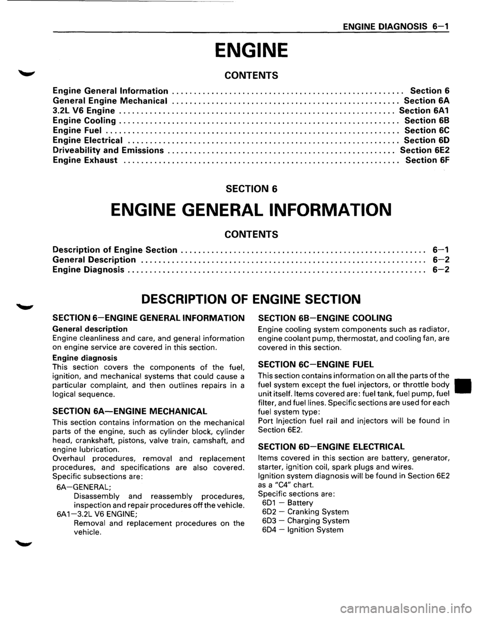
ENGINE DIAGNOSIS S-1
ENGINE
CONTENTS
Engine General Information . . . . . . . . . . . . . . . . . . . . . . . . . . . . . . . . . . . . . . . . . . . . . . . . . . . . . Section S
General
Engine Mechanical .................................................... Section SA
3.2L VS Engine ............................................................... Section SA1
Engine Cooling . . . . . . . . . . . . . . . . . . . . . . . . . . . . . . . . . . . . . . . . . . . . . . . . . . . . . . . . . . . . . . . . Section S8
Engine Fuel . . . . . . . . . . . . . . . . . . . . . . . . . . . . . . . . . . . . . . . . . . . . . . . . . . . . . . . . . . . . . . . . . . . Section SC
Engine Electrical . . . . . . . . . . . . . . . . . . . . . . . . . . . . . . . . . . . . . . . . . . . . . . . . . . . . . . . . . . . . . . Section SD
Driveability and Emissions . . . . . . . . . . . . . . . . . . . . . . . . . . . . . . . . . . . . . . . . . . . . . . . . . . . . Section SE2
Engine Exhaust . . . . . . . . . . . . . . . . . . . . . . . . . . . . . . . . . . . . . . . . . . . . . . . . . . . . . . . . . . . . . . . Section SF
SECTION 6
ENGINE GENERAL INFORMATION
CONTENTS
Description of Engine Section . . . . . . . . . . . . . . . . . . . . . . . . . . . . . . . . . . . . . . . . . . . . . . . . . . . . . . . . S-1
General Description . . . . . . . . . . . . . . . . . . . . . . . . . . . . . . . . . . . . . . . . . . . . . . . . . . . . . . . . . . . . . . . . . S-2
Engine Diagnosis . . . . . . . . . . . . . . . . . . . . . . . . . . . . . . . . . . . . . . . . . . . . . . . . . . . . . . . . . . . . . . . . . . . . S-2
DESCRIPTION OF ENGINE SECTION
SECTIONS-ENGINE GENERAL INFORMATION SECTION S8-ENGINE COOLING
General description
Engine cleanliness and care, and general information
on engine service are covered in this section.
Engine diagnosis
This section covers the components of the fuel,
ignition, and mechanical systems that could cause a
particular complaint, and then outlines repairs in a
logical sequence.
SECTION SA-ENGINE MECHANICAL
This section contains information on the mechanical
parts of the engine, such as cylinder block, cylinder
head, crankshaft, pistons, valve train, camshaft, and
engine
lubrication.
Overhaul
procedures, removal and replacement
procedures, and specifications are also covered.
Specific subsections are:
SA-GENERAL;
Disassembly and reassembly procedures,
inspection and repair procedures
off the vehicle.
6A 1-3.2L V6 ENGINE;
Removal
and replacement procedures on the
vehicle.
Engine cooling system components such as radiator,
engine
coolant pump, thermostat, and cooling fan, are
covered
in this section.
SECTION SC-ENGINE FUEL
This section contains information on all the parts of the
fuel system except the fuel injectors, or throttle body II
unit itself. Items covered are: fuel tank, fuel pump, fuel
filter,
and fuel lines. Specific sections are used for each
fuel system type:
Port
Injection fuel rail and injectors will be found in
Section
6E2.
SECTION SD-ENGINE ELECTRICAL
Items covered in this section are battery, generator,
starter, ignition
coil, spark plugs and wires.
Ignition system diagnosis will be found in Section 6E2
as a "C4" chart.
Specific sections are:
601 -Battery
602 - Cranking System
603 -Charging System
604 -Ignition System
Page 504 of 1928
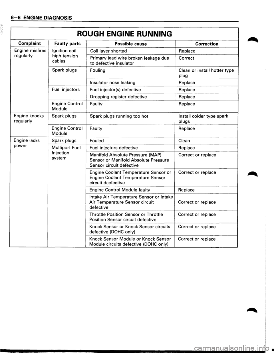
6-6 ENGINE DIAGNOSIS
ROUGH ENGINE RUNNING
Complaint
Faulty parts Possible cause Correction
Engine misfires Ignition coil
Coil layer shorted Replace
regularly
high-tension Primary lead wire broken leakage due
Correct cables to defective insulator
Spark plugs
Fouling Clean
or install hotter type
plug
Insulator
nose leaking Replace
Fuel
injectors Fuel injector(s) defective Replace
Dropping register defective Replace
Engine Control
Faulty Replace
Module
Engine knocks Spark plugs
Spark plugs running too hot Install colder type spark
regularly
plugs
Engine Control Faulty
Replace
Module
Engine lacks Spark plugs
Fouled Clean
power Multipart Fuel
Fuel injectors defective Replace
Injection Manifold Absolute Pressure (MAP)
Correct or replace system Sensor or Manifold Absolute Pressure
Sensor
circuit defective
Engine
Coolant Temperature Sensor or Correct or replace
Engine Coolant Temperature Sensor
circuit dcefective
Engine
Control Module faulty Replace
Intake
Air Temperature Sensor or Intake
Air Temperature Sensor circuit Correct or replace
defective
Throttle Position Sensor or Throttle Correct or replace
Position Sensor
circuit defective
Knock
Sensor or Knock Sensor circuits Correct or replace
defective (DOHC only)
Knock Sensor Module or Knock Sensor Correct or replace .
Module
circuits defective (DOHC only)
•
Page 561 of 1928
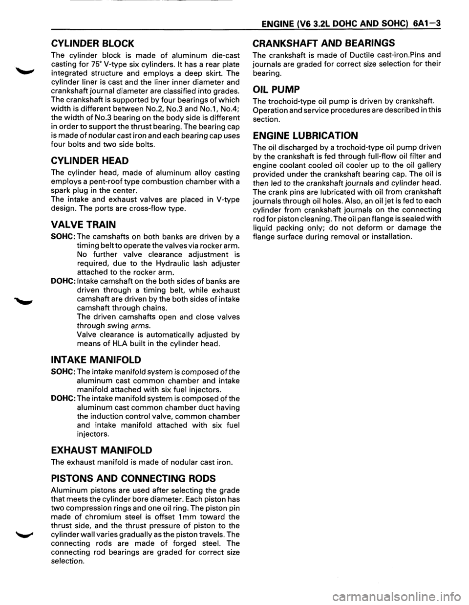
CYLINDER BLOCK
The cylinder block is made of aluminum die-cast
casting
for 75° V-type six cylinders. It has a rear plate
integrated structure and employs a deep skirt. The
cylinder liner is cast and the liner inner diameter and
crankshaft
journal diameter are classified into grades.
The crankshaft is supported by four bearings
of which
width is different between No.2, No.3 and No.1, No.4;
the
width of No.3 bearing on the body side is different
in order
to support the thrust bearing. The bearing cap
is made
of nodular cast iron and each bearing cap uses
four bolts and two side bolts.
CYLINDER HEAD
The cylinder head, made of aluminum alloy casting
employs a pent-roof type combustion chamber with a
spark
plug in the center.
The intake and exhaust
valves are placed in V-type
design. The ports are cross-flow type.
VALVE TRAIN
SOHC: The camshafts on both banks are driven by a
timing
belt to operate the valves via rocker arm.
No
further valve clearance adjustment is
required, due
to the Hydraulic lash adjuster
attachedtotherockerarm.
DOHC: Intake camshaft on the both sides of banks are
driven through a
timing belt, while exhaust
camshaft are driven by the both sides
of intake
camshaft through chains.
The driven camshafts open and
close valves
through swing arms.
Valve clearance is automatically adjusted by
means
of HLA built in the cylinder head.
INTAKE MANIFOLD
SOHC: The intake manifold system is composed ofthe
aluminum cast common chamber and intake
manifold attached with six fuel injectors.
DOHC: The intake manifold system is composed of the
aluminum cast common chamber duct having
the induction
control valve, common chamber
and intake
manifold attached with six fuel
injectors.
EXHAUST MANIFOLD
The exhaust manifold is made of nodular cast iron.
PISTONS AND CONNECTING RODS
Aluminum pistons are used after selecting the grade
that meets the cylinder bore diameter. Each piston has
two compression rings and one oil ring. The piston pin
made
of chromium steel is offset 1 mm toward the
thrust side, and the thrust pressure
of piston to the
cylinder wall varies gradually as the piston travels. The
connecting rods are made
of forged steel. The
connecting rod bearings are graded
for correct size
selection.
ENGINE (V6 3.2L DOHC AND SOHC) 6A1-3
CRANKSHAFT AND BEARINGS
The crankshaft is made of Ductile cast-iron.Pins and
journals are graded for correct size selection for their
bearing.
OIL PUMP
The trochoid-type oil pump is driven by crankshaft.
Operation and service procedures are described in this
section.
ENGINE LUBRICATION
The oil discharged by a trochoid-type oil pump driven
by the crankshaft is fed through full-flow oil filter and
engine
coolant cooled oil cooler up to the oil gallery
provided under the crankshaft bearing cap. The oil is
then
led to the crankshaft journals and cylinder head.
The crank pins are
lubricated with oil from crankshaft
journals through oil holes. Also, an oil jet is fed to each
cylinder from crankshaft journals on the connecting
rod
for piston cleaning. The oil pan flange is sealed with
liquid packing only; do not deform or damage the
flange surface during removal or installation.
Page 621 of 1928
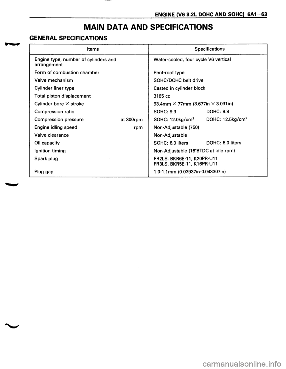
·-------------------------------------
ENGINE (V6 3.2L DOHC AND SOHC) 6A1-63
MAIN DATA AND SPECIFICATIONS
GENERAL SPECIFICATIONS
Items S pacifications
Engine type,
number of cylinders and Water-cooled, four cycle V6 vertical
arrangement
Form
of combustion chamber
Pent-roof type
Valve mechanism SOHC/DOHC belt drive
Cylinder liner type
Casted in cylinder block
Total
piston displacement
3165 cc
Cylinder bore X stroke 93.4mm X 77mm (3.677in X 3.031 in)
Compression ratio
SOHC: 9.3 DOHC: 9.8
Compression pressure
at
300rpm SOHC: 12.0kg/cm2 DOHC: 12.5kg/cm2
Engine idling speed rpm Non-Adjustable (750)
Valve clearance Non-Adjustable
Oil capacity SOHC: 6.0 liters DOHC:
6.0 liters
Ignition
timing Non-Adjustable (16.BTDC at Idle rpm)
Spark
plug FR2LS, BKR6E-11, K20PR-U11
FR3LS, BKR5E-11 I K16PR-U11
Plug gap 1.0-1.1 mm (0.03937in-0.043307in)