oil type ISUZU TROOPER 1995 Service Manual
[x] Cancel search | Manufacturer: ISUZU, Model Year: 1995, Model line: TROOPER, Model: ISUZU TROOPER 1995Pages: 1928
Page 1511 of 1928
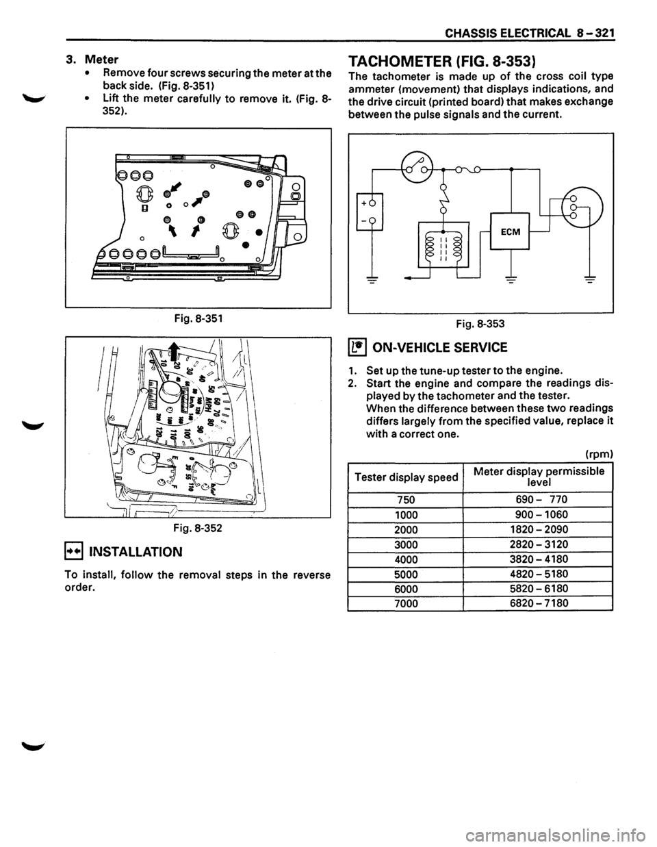
3. Meter
• Remove four screws securing the meter at the
back side. (Fig.
8-351)
• Lift the meter carefully to remove it. (Fig. 8-
352).
0
q;J"' 0
0 0 0,
0 0
0 I
Fig. 8-351
Fig. 8-352
E) INSTALLATION
00
0
To install, follow the removal steps in the reverse
order.
CHASSIS ELECTRICAL 8-321
TACHOMETER (FIG. 8-353)
The tachometer is made up of the cross coil type
ammeter (movement) that displays indications, and
the drive circuit (printed board)
that makes exchange
between the
pulse signals and the current.
Fig.
8-353
(1!1 ON-VEHICLE SERVICE
1. Set up the tune-up tester to the engine.
2. Start the engine and compare the readings dis
played by the tachometer and the tester.
When the difference between these
two readings
differs
largely from the specified value, replace it
with a correct one.
(rpm)
Tester
display speed Meter
display permissible level
750 690-770
1000
900-1060
2000 1820-2090
3000 2820-3120
4000 3820-4180
5000 4820-5180
6000 5820-6180
7000 6820-7180
Page 1649 of 1928
, Supplem~l Restraint System
SPECIAL TOOLS
WARNING: TO AVOID DEPLOYMENT WHEN
'-' TROUBLESHOOTING THE SRS, DO NOT USE
ELECTRICAL TEST EQUIPMENT SUCH AS A
BATTERY-POWERED OR AC-POWERED
VOLTMETER, OHMMETER, ETC., OR ANY TYPE OF
ELECTRICAL EQUIPMENT OTHER THAN THAT
SPECIFIED IN THIS MANUAL. DO NOT USE A
NON-POWERED PROBE TYPE TESTER.
INSTRUCTIONS IN THIS MANUAL MUST BE
FOLLOWED CAREFULLY, OTHERWISE PERSONAL
INJURY
MAY RESULT.
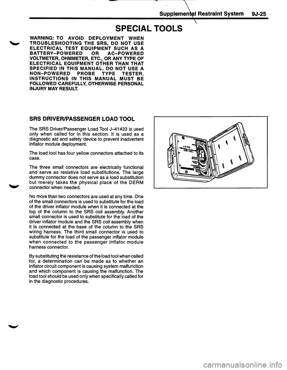
SRS DRIVER/PASSENGER LOAD TOOL
The SRS Driver/Passenger Load Tool J-41433 is used
only when called for in this section. It is used as a
diagnostic aid and safety device to prevent inadvertent
inflator
module deployment.
The
load tool has four yellow connectors attached to its
case.
The three
small connectors are electrically functional
and serve as resistive
load substitutions. The large
dummy connector does not serve as a load substitution
but
merely takes the physical place of the DERM
connector when needed.
No more than two connectors are used at any time.
One
of the small connectors is used to substitute for the load
of the driver inflator module when it is connected at the
top of the
column to the SRS coil assembly. Another
small connector is used to substitute for the load of the
driver inflator
module and the SRS coil assembly when
it is connected at the base of the
column to the SRS
wiring harness. The third small connector is used to
substitute for the
load of the passenger inflator module
when connected to the passenger inflator module
harness connector.
By substituting the resistance of the
load tool when called
for, a determination can be made as to whether an
inflator circuit component is causing system malfunction
and which component is causing the malfunction. The
load tool should be used only when specifically called for
in the diagnostic procedures.
9J-25
Page 1741 of 1928
Supplemental Restraint System 9J-117
SERVICE PRECAUTIONS
CAUTION: WHEN PERFORMING SERVICE ON OR
AROUND SRS COMPONENTS OR SRS WIRING,
FOLLOW
THE PROCEDURES LISTED BELOW TO
TEMPORARILY
DISABLE THE SRS. FAILURE TO
FOLLOW PROCEDURES COULD RESULT IN
POSSIBLE AIR BAG DEPLOYMENT, PERSONAL
INJURY OR OTHERWISE UNNEEDED SRS
REPAIRS.
The DERM in Driver-Passenger SRS can maintain
sufficient voltage to cause a deployment for up to 2
minutes after the ignition switch is turned to
"OFF," the
battery is disconnected, or the fuse powering the DERM
is removed.
Many of the service procedures require removal of the
"AIR BAG" fuse, and disconnection of the inflator
modules from the deployment loop to avoid an accidental
deployment.
If the inflator module is disconnected from
the deployment loop as noted in the "Disabling the
SRS"
procedure that follows, service can begin immediately
without waiting for the 2 minute time period to expire.
DISABLING THE SRS
REMOVAL
• Turn the steering wheel so that the vehicle's wheels
are pointing straight ahead.
• Turn the ignition switch to "OFF"
1. Remove SRS fuse C-21, C-22, C-23 and C-24 from
left dash side lower fuse block.
2. Disconnect yellow
3-way connector at the base of
the steering column.
3. Remove
liP compartment door assembly, Refer to
"Passenger inflator module replacemenf' in section
9J-135.
4. Disconnect yellow 4-way connector behind the liP
compartment door assembly.
NOTE
• With the" AIR BAG" fuse removed and ignition switch
"ON," the "AiR BAG" warning lamp will be "ON." This
is normal operation and does not indicate
an SRS
malfunction.
ENABLING THE SRS
INSTALLATION
Turn ignition switch to "LOCK" and remove key.
1. Connect yellow 4-way connector of passenger
inflator module.
2. Install liP compartment door assembly, Refer to
"Passenger inflator module replacement" in section
9J-3.
3. Connect yellow 3-way connector at the base of the
steering column.
4. Install" AIR BAG" fuse C-21, C-22, C-23 and C-24 to
left dash side lower fuse block.
Tum ignition switch to
"RUN" and verify that the "AIR
BAG"
warning lamp flashes seven times and then turns
"OFF" If it does not operate as described, perform the
"SRS Diagnostic System Check" in section 9J-32.
HANDLING/INSTALLATION/DIAGNOSIS
1. Inflator modules should not be subjected to
temperatures above 65°C(150°F).
2. Discriminating s~nsors, inflator modules, arming
sensors, or DERMs should not be used if they have
been dropped from a height of 1
00 centimeters (3.28
feet) or more.
3. When a discriminating sensor or arming sensor is
replaced, it MUST be oriented with the arrow
on the
sensor pointing toward the front of the vehicle.
It is
very important for the discriminating sensors and
arming sensor to be located flat on the mounting
surface, parallel to the vehicle datum line.
It is
important that the sensor mounting surface is free of
any dirt or other foreign material.
4. Do not apply power to the SRS unless all
components are connected or a diagnostic chart
requests it, as this
will set a diagnostic trouble code.
5. The
"SRS Diagnostic System Check'' must be the
starting point of any SRS diagnostics. The
"SRS
Diagnostic System Check" will verify proper "AIR
BAG" warning lamp operation and will lead you to the
correct chart to diagnose any SRS malfunctions.
Bypassing these procedures may result in extended
diagnostic time, incorrect diagnosis, and incorrect
parts replacements.
INSPECTIONS REQUIRED AFTER ACCI
DENT
CAUTION: CERTAIN SRS COMPONENTS MUST BE
REPLACED AFTER A FRONTAL
CRASH INVOLVING
AIR
BAG DEPLOYMENT.
In all types of accident regardless of "Air Bag"
deployment, visually inspect all the following
components and their points and replace as required:
- Passenger
Inflator Module
- Steering wheel
- SRS coil assembly
- Steering column
- Knee bolster and
Instrument panel mounting