timing belt ISUZU TROOPER 1995 Owner's Manual
[x] Cancel search | Manufacturer: ISUZU, Model Year: 1995, Model line: TROOPER, Model: ISUZU TROOPER 1995Pages: 1928
Page 606 of 1928
~:· T·, ·.}:
6A1-48 ENGINE (V6 3.2L DOHC AND SOHC)
33. Cylinder head cover
• Remove 11 fixing bolts, then the cylinder head
cover.
34. Power steering pump bracket
• Disconnect ground cable from bracket.
35.
• Remove five fixing bolts, then the bracket.
Exhaust front pipe
36.
37. Level gage fixing bolt
• Remove from cylinder head.
Cylinder head
1••1 INSTALLATION
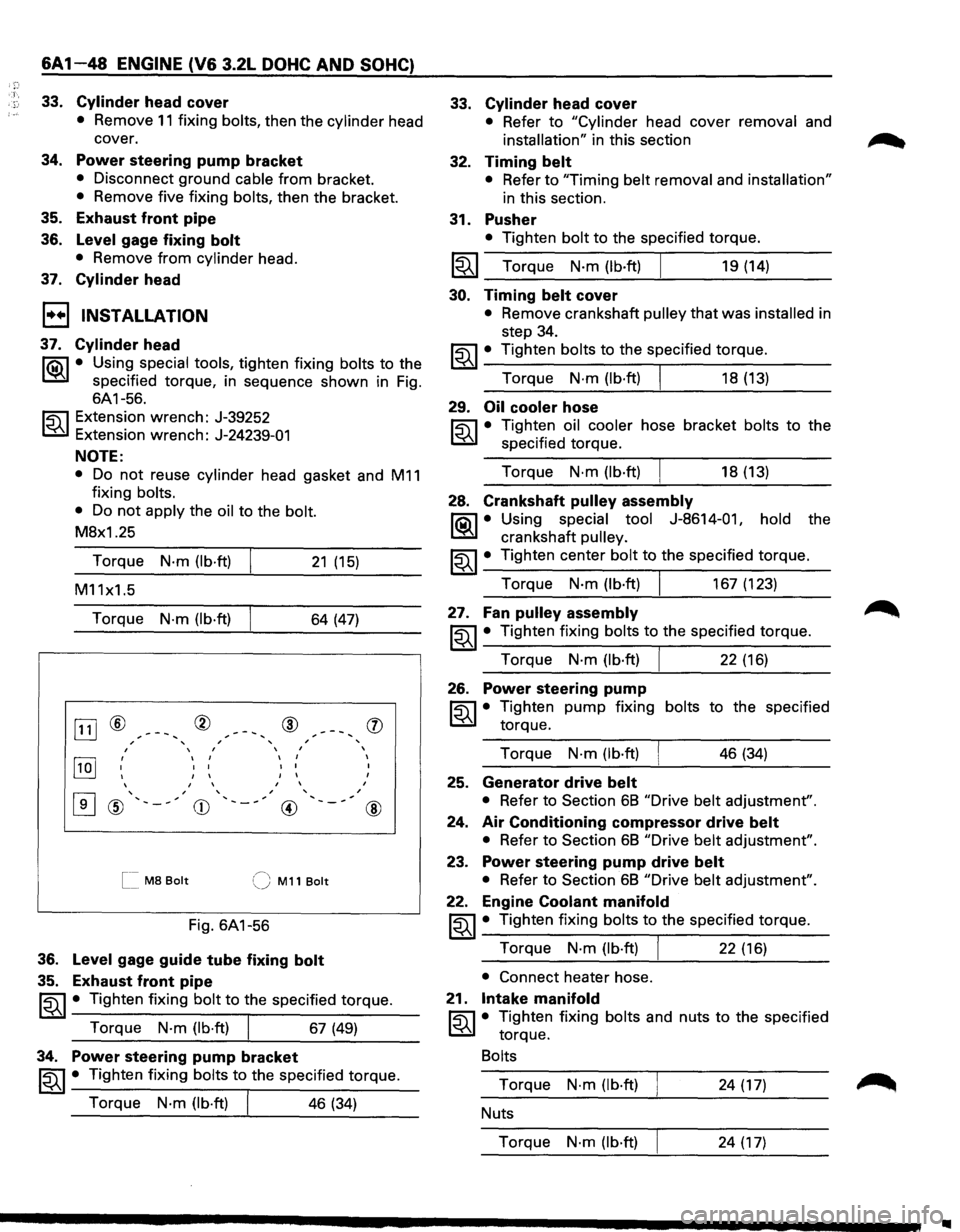
37. Cylinder head
li0\1 • Using special tools, tighten fixing bolts to the
~ specified torque, in sequence shown in Fig.
6A1-56.
~ Extension wrench: J-39252
t:6.l Extension wrench: J-24239-01
NOTE:
• Do not reuse cylinder head gasket and M11
fixing bolts.
•
Do not apply the oil to the bolt.
M8x1.25
Torque
N·m (lb·ft) 21 (15)
M11x1.5
Torque
N·m (lb·ft) 64 (47)
OJ] ® ® ® , ' ' ,
, I , ,
[IQJ ' I I
I I
I I I
I I
I I I
I I
,
[I] ' , , ' @ ' ,
CD ' , , __
@
[[ M8 Bolt (J M11 Bolt
Fig.
6A1-56
36. Level gage guide tube fixing bolt
35. Exhaust front pipe
'
,
(])
I
I
I
,
@
~~~ • Tighten fixing bolt to the specified torque.
Torque
N·m (lb·ft) I 67 (49)
34. Power steering pump bracket
~~~ • Tighten fixing bolts to the specified torque.
Torque
N·m (lb·ft) I 46 (34)
33.
32.
31.
Cylinder head cover
• Refer to "Cylinder head cover removal and
installation" in this section
Timing belt
• Refer to "Timing belt removal and installation"
in this section.
Pusher
• Tighten bolt to the specified torque.
I~I __ T_o_r~qu_e __ N_·_m~(lb_·ft_)~ ______ 1_9_(1_4_) ____ _
30. Timing belt cover
• Remove crankshaft pulley that was installed in
step 34.
~~~· Tighten bolts to the specified torque.
Torque
N·m (lb·ft) I 18 (13)
29. Oil cooler hose
~ • Tighten oil cooler hose bracket bolts to the
t:6.l specified torque.
Torque
N·m (lb·ft) I 18 (13)
28. Crankshaft pulley assembly
li0\1 • Using special tool J-8614-011 hold the
~ crankshaft pulley.
~~~ • Tighten center bolt to the specified torque.
Torque
N·m (lb·ft) I 167 (123)
27. Fan pulley assembly
~~~· Tighten fixing bolts to the specified torque.
Torque
N·m (lb·ft) I 22 (16)
26. Power steering pump
~ • Tighten pump fixing bolts to the specified
t:6.l torque.
Torque
N·m (lb·ft) I 46 (34)
25. Generator drive belt
• Refer to Section 68 "Drive belt adjustment".
24.
Air Conditioning compressor drive belt
• Refer to Section 68 "Drive belt adjustment".
23. Power steering pump drive belt
• Refer to Section 68 "Drive belt adjustment".
22. Engine Coolant manifold
~~~· Tighten fixing bolts to the specified torque.
Torque
N·m (lb·ft) I 22 (16)
• Connect heater hose.
21.
Intake manifold
~ • Tighten fixing bolts and nuts to the specified
t:6.l torque.
Bolts
Torque N·m (lb·ft) 24 (17)
Nuts
Torque
N·m (lb·ft) 24 (17)
..
Page 610 of 1928
6A 1-52 ENGINE (V6 3.2L DOHC AND SOHC)
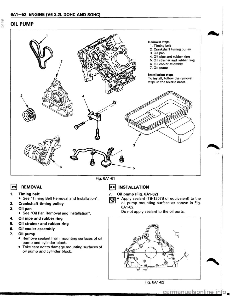
OIL PUMP
7
2
•
4
3
5
Removal steps 1. Timing belt 2. Crankshaft timing pulley
3.
Oil pan
4. Oil pipe and rubber ring 5. Oil strainer and rubber ring
6. Oil cooler assembly
7. Oil pump
Installation steps To install, follow the removal steps in the reverse order.
Fig. 6A1-61
1••1 REMOVAL
1. Timing belt
• See "Timing Belt Removal and Installation".
2. Crankshaft timing pulley
3. Oil pan
• See "Oil Pan Removal and Installation".
4. Oil pipe and rubber ring
5. Oil strainer and rubber ring
6. Oil cooler assembly
7. Oil pump
• Remove sealant from mounting surfaces of oil
pump and cylinder block.
•
Take care not to damage mounting surfaces of
oil pump and cylinder block.
1••1 INSTALLATION
7. Oil pump (Fig. 6A1·62)
rEi1 • Apply sealant (TB-12078 or equivalent) to the
l:!!J oil pump mounting surface as shown in Fig.
6A1-62.
Do not apply sealant to the oil ports.
Fig. 6A1-62
I
~)
•
Page 611 of 1928
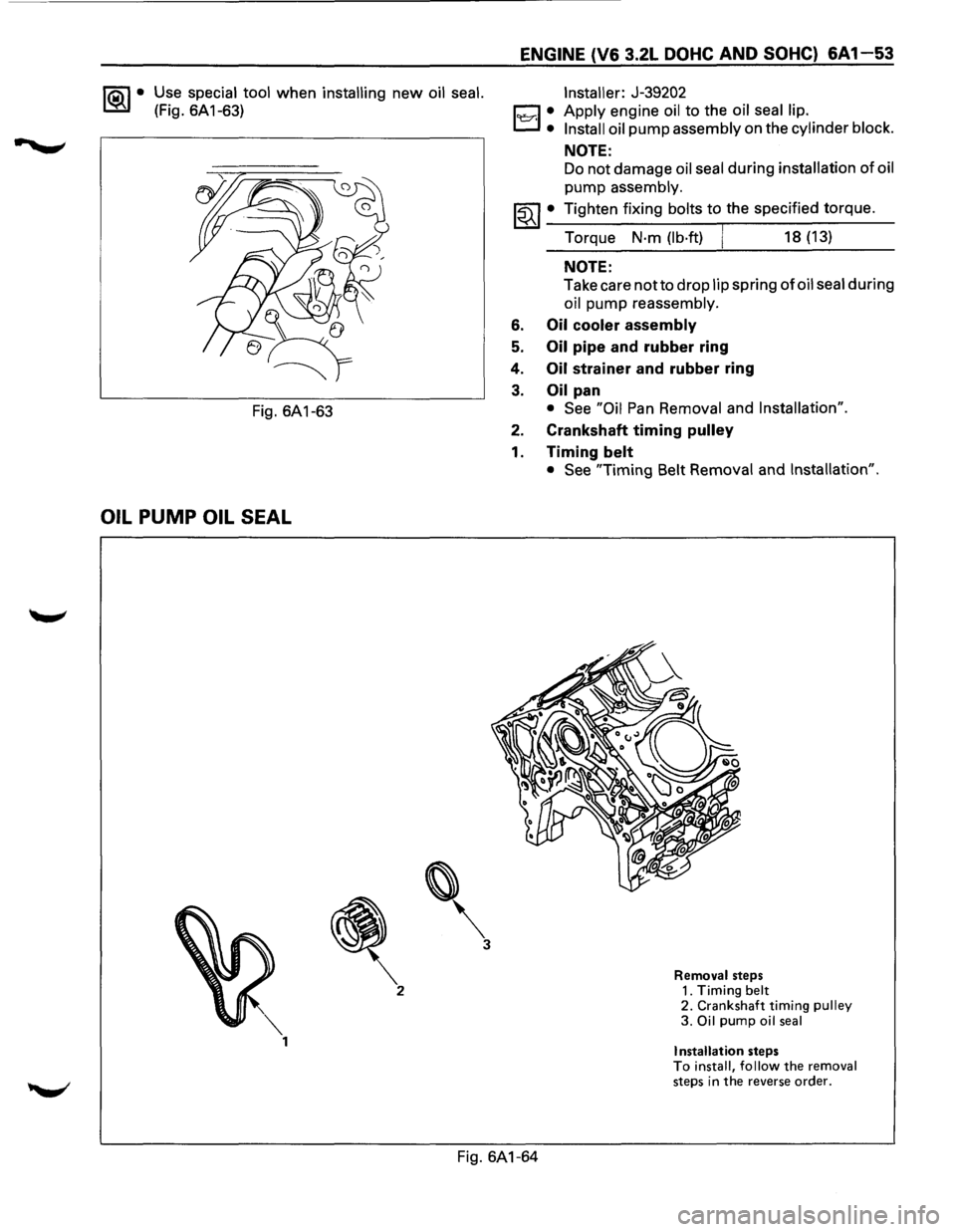
1®.1• Use special tool when installing new oil seal.
(Fig. 6A 1-63)
Fig. 6A1-63
OIL PUMP OIL SEAL
'
3
ENGINE (V6 3.2L DOHC AND SOHC) 6A 1-53
l'l::r.l :
Installer: J-39202
Apply
engine oil to the oil seal lip.
Install oil
pump assembly on the cylinder block.
NOTE:
Do not damage oil seal during installation of oil
pump assembly.
~~~· Tighten fixing bolts to the specified torque.
Torque
N·m (lb·ft) 18 (13)
NOTE:
Take care notto drop lip spring of oil seal during
oil pump reassembly.
6. Oil cooler assembly
5. Oil pipe and rubber ring
4.
Oil strainer and rubber ring
3. Oil pan
• See "Oil Pan Removal and Installation".
2. Crankshaft timing pulley
1. Timing belt
• See "Timing Belt Removal and Installation".
Removal steps 1. Timing belt 2. Crankshaft timing pulley 3. Oil pump oil seal
Installation steps To install, follow the removal steps in the reverse order.
Fig. 6A1-64
Page 612 of 1928
6A1-54 ENGINE (V6 3.2L DOHC AND SOHC)
1••1 REMOVAL
1. Timing belt
• See "Timing Belt Removal and Installation".
2. Crankshaft timing pulley
3. Oil pump oil seal
• Remove oil seal using a sealer puller.
NOTE:
Take care not to damage sealing surfaces of oil
pump and crankshaft when removing oil seal.
1••1 INSTALLATION
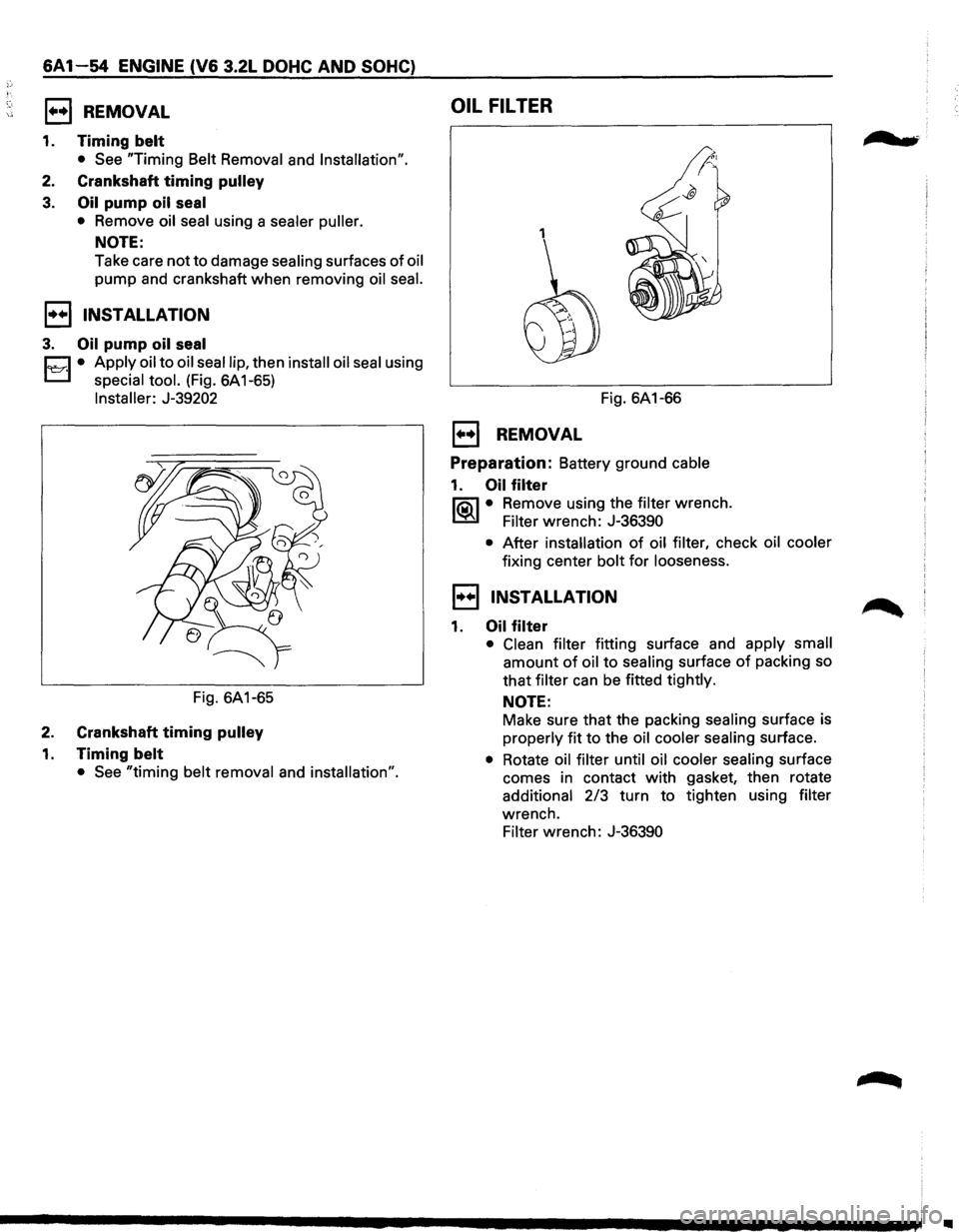
3. Oil pump oil seal
Cl • Apply oil to oil seal lip, then install oil seal using
L..:::::.l special tool. (Fig. 6A1-65)
Installer: J-39202
Fig. 6A1-65
2. Crankshaft timing pulley
1. Timing belt
• See "timing belt removal and installation".
OIL FILTER
1
Fig. 6A1-66
E) REMOVAL
Preparation: Battery ground cable
1. Oil filter
lia\l • Remove using the filter wrench.
~ Filter wrench: J-36390
• After installation of oil filter, check oil cooler
fixing center bolt for looseness.
1••1 INSTALLATION
1. Oil filter
• Clean filter fitting surface and apply small
amount of oil to sealing surface of packing so
that filter can be fitted tightly.
NOTE:
Make sure that the packing sealing surface is
properly fit to the oil cooler sealing surface.
• Rotate oil filter until oil cooler sealing surface
comes in contact
with gasket, then rotate
additional 2/3 turn to tighten using filter
wrench.
Filter wrench: J-36390
, ...
Page 616 of 1928
,): .. • T·
6A 1-58 ENGINE (V6 3.2L DOHC AND SOHC)
EJ REMOVAL
1. Engine assembly
• See "Engine Assembly
Removal and Instal-
lation".
2. Crankshaft pulley
3. Timing belt cover
4. Timing belt
5. Oil pan
6. Oil pipe and rubber ring
7. Oil strainer and rubber ring
8. Oil pump assembly
9. Crankcase side bolts
10.
Oil gallery
11. Flywheel
12.
Rear oil seal retainers
13.
Connecting rod caps
14.
Crankshaft main bearing caps
15.
Crankshaft and main bearings
1•+1 INSTALLATION
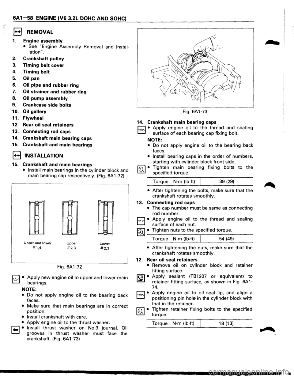
15. Crankshaft and main bearings
• Install main bearings in the cylinder block and
main bearing cap respectively. (Fig. 6A1-72)
r-r-'
II-
!:=
Upper and lower
#1,4
~
!::
E:
Upper
#2,3
Fig. 6A1-72
Lower
#2,3
1~1· Apply new engine oil to upper and lower main
bearings.
NOTE:
• Do not apply engine oil to the bearing back
faces.
• Make sure that main bearings are in correct
position.
• Install crankshaft with care.
• Apply engine oil to the thrust washer.
1•1• Install thrust washer on No.3 journal. Oil
grooves in thrust washer must face the
crankshaft. (Fig. 6A1-73) Fig.
6A1-73
14. Crankshaft main bearing caps
C1 • Apply engine oil to the thread and seating
L:::J surface of each bearing cap fixing bolt.
NOTE:
• Do not apply engine oil to the bearing back
faces.
• Install bearing caps in the order of numbers,
starting
with cylinder block front side.
~~~ • Tighten main bearing fixing bolts to the
specified torque.
Torque
N·m (lb·ft) I 39 (29)
• After tightening the bolts, make sure that the
crankshaft rotates
smoothly.
13. Connecting rod caps
• The cap number must be same as connecting
rod number.
1~1· Apply engine oil to the thread and sealing
surface of each nut.
~~~· Tighten nuts to the specified torque.
Torque
N·m (lb·ft) 54 (49)
• After tightening the nuts, make sure that the
crankshaft rotates
smoothly.
12. Rear oil seal retainers
• Remove oil on cylinder block and retainer
fitting surface.
~~~· Apply sealant (TB1207 or equivalent) to
retainer fitting surface, as shown in Fig. 6A 1-
74.
C1 • Apply engine oil to oil seal lip, and align a
El positioning pin hole< in the cylinder block with
that in the retainer.
~~~· Tighten retainer fixing bolts to the specified
torque.
Torque
N·m (lb·ft) 18 (13)
IIIII
Page 618 of 1928
6A1-60 ENGINE (V6 3.2L DOHC AND SOHC}
4. Timing belt
• See "Timing Belt Removal and Installation".
3. Timing belt cover
2. Crankshaft pulley
~ • Using special tool J-8614-01, hold the
~ crankshaft pulley.
~~~· Tighten center bolt to the specified torque.
Torque
N·m (lb·ft) 167 (123)
1. Engine assembly
• See "Engine Assembly Removal and Instal
lation".
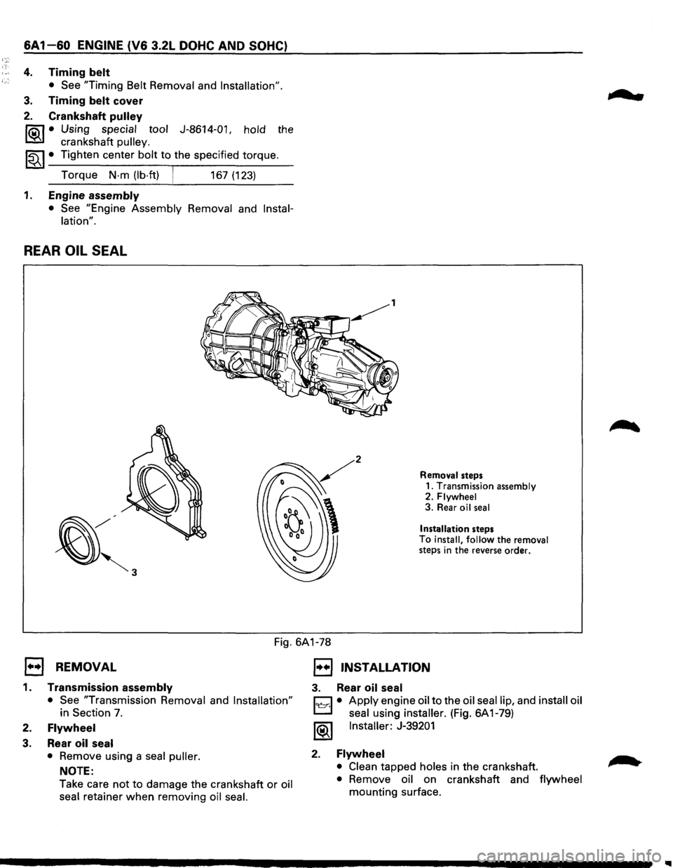
REAR OIL SEAL
Removal steps
1. Transmission assembly
2.
Flywheel 3. Rear oil seal
Installation steps To install, follow the removal
steps in the reverse order.
Fig. 6A1-78
E) REMOVAL
1. Transmission assembly
• See "Transmission Removal and Installation"
in Section 7.
2. Flywheel
3. Rear oil seal
•
Remove using a seal puller.
NOTE:
Take care
not to damage the crankshaft or oil
seal retainer
when removing oil seal.
1••1 INSTALLATION
3. Rear oil seal
C1 • Apply engine oil to the oil seal lip, and install oil
L:::l seal using installer. (Fig. 6A 1-79)
1®1 Installer: J-39201
2. Flywheel
• Clean tapped holes in the crankshaft.
• Remove oil on crankshaft and flywheel
mounting surface.
...
Page 621 of 1928
·-------------------------------------
ENGINE (V6 3.2L DOHC AND SOHC) 6A1-63
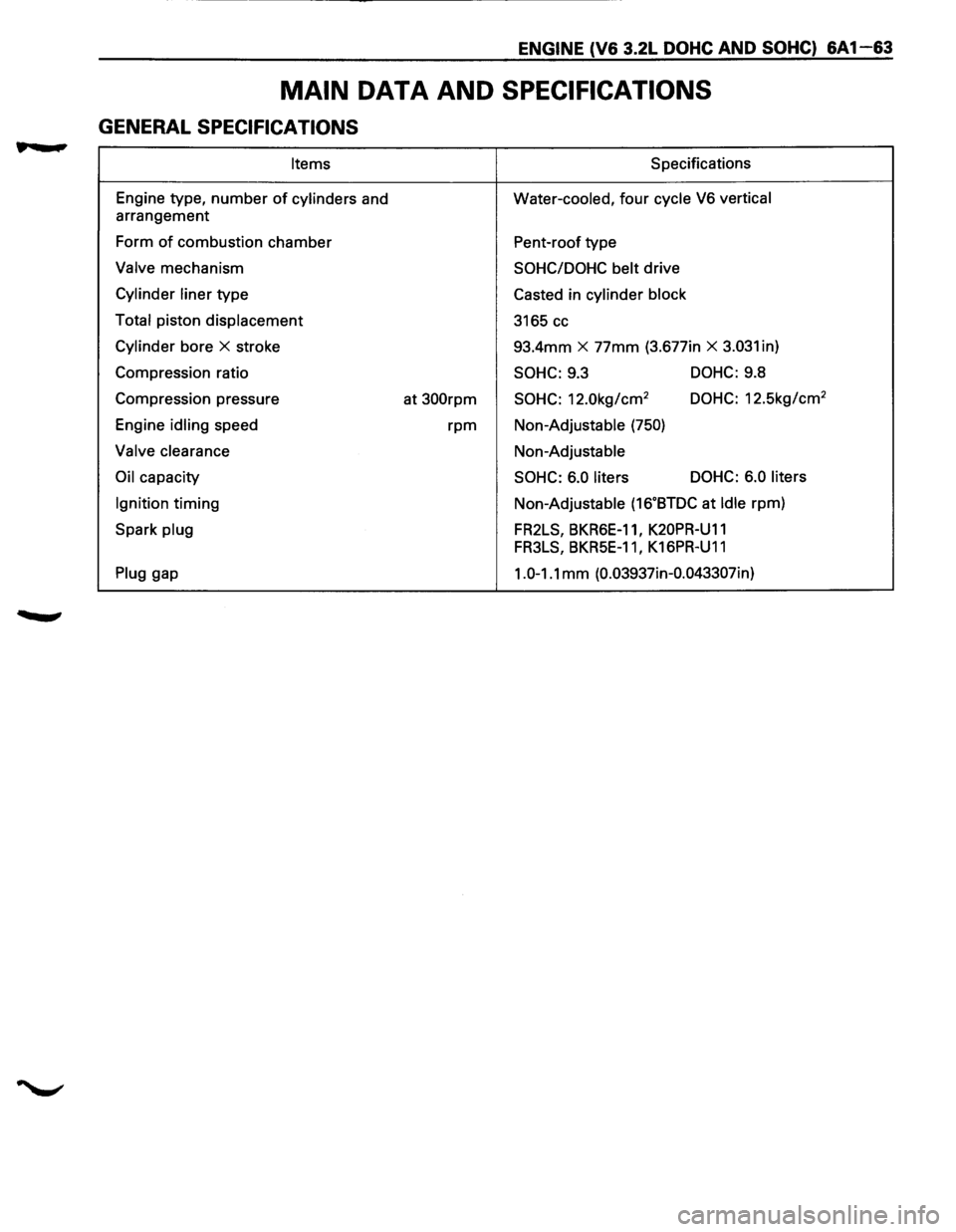
MAIN DATA AND SPECIFICATIONS
GENERAL SPECIFICATIONS
Items S pacifications
Engine type,
number of cylinders and Water-cooled, four cycle V6 vertical
arrangement
Form
of combustion chamber
Pent-roof type
Valve mechanism SOHC/DOHC belt drive
Cylinder liner type
Casted in cylinder block
Total
piston displacement
3165 cc
Cylinder bore X stroke 93.4mm X 77mm (3.677in X 3.031 in)
Compression ratio
SOHC: 9.3 DOHC: 9.8
Compression pressure
at
300rpm SOHC: 12.0kg/cm2 DOHC: 12.5kg/cm2
Engine idling speed rpm Non-Adjustable (750)
Valve clearance Non-Adjustable
Oil capacity SOHC: 6.0 liters DOHC:
6.0 liters
Ignition
timing Non-Adjustable (16.BTDC at Idle rpm)
Spark
plug FR2LS, BKR6E-11, K20PR-U11
FR3LS, BKR5E-11 I K16PR-U11
Plug gap 1.0-1.1 mm (0.03937in-0.043307in)
Page 630 of 1928
68 - 2 ENGINE COOLING
The cooling system is a pressurized Engine Coolant
(EC) forced circulation type which consists of water
pump, thermostat cooling fan, radiator and other
components. The automatic transmission fluid is
cooled by the EC in radiator.
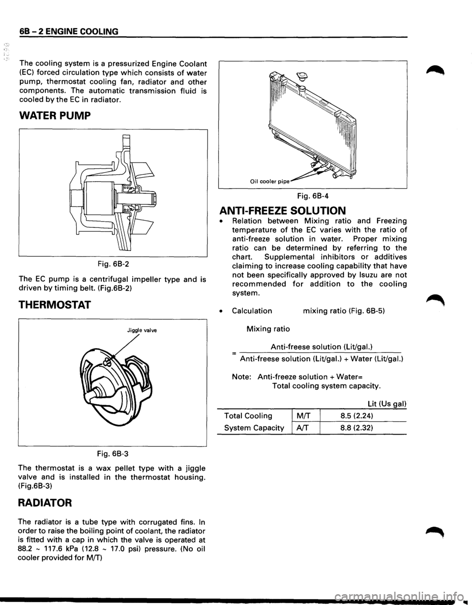
WATER PUMP
Fig. 68-2
The
EC pump is a centrifugal impeller type and is
driven by timing belt. (Fig.68-2)
THERMOSTAT
Jiggle valve
Fig. 68-3
The
thermostat is a wax pellet type with a jiggle
valve and is installed in the thermostat housing.
(Fig.68-3)
RADIATOR
The radiator is a tube type with corrugated fins. In
order to raise the boiling point of coolant, the radiator
is fitted
with a cap in which the valve is operated at
88.2
-117.6 kPa (12.8 - 17.0 psi) pressure. (No oil
cooler
provided for M!f)
Fig. 68-4
ANTI-FREEZE SOLUTION
•
•
Relation between Mixing ratio and Freezing
temperature
of the EC varies with the ratio of
anti-freeze solution in water. Proper mixing
ratio can be determined by referring to the
chart. Supplemental inhibitors or additives
claiming to increase cooling capability that have
not been specifically approved by lsuzu are not
recommended for addition to the cooling
system.
Calculation mixing ratio (Fig. 68-5)
Mixing ratio
Anti-freese
solution (Lit/gal.) =-----------------Anti-freese solution (Lit/gal.) +Water (Lit/gal.)
Note: Anti-freeze solution +Water=
Total cooling system capacity.
Lit (Us
gal)
Total Cooling
M!f 8.5 (2.24) ~-~~--------System Capacity AfT 8.8 (2.32)
Page 632 of 1928
68 - 4 ENGINE COOLING
ON-VEHICLE SERVICE
DRAINING AND REFILLING COOLING
SYSTEM
Before draining the cooling system, inspect the sys
tem and perform any necessary service to ensure that
it is clean, does not leak and is in proper working
order. The Engine Coolant (EC) level should be be
tween the "MIN" and "MAX" lines of reserve tank
when the engine is cold. If low, check for leakage and
add
EC up to the "MAX" line. There should not be any
excessive deposit of rust or scales around the radiator
cap
or radiator filler hole, and the EC should also be
free
from oil. Replace the EC if excessively dirty.
1. Completely drain the cooling system by opening
the drain petcock at the bottom of the radiator.
2. Remove the radiator cap.
W WARNING
To avoid the danger of being burned, do not
remove the cap while the engine and radiator
are still hot. Scalding fluid and steam can be
blown out under pressure.
3. Disconnect all hoses from the EC reserve tank.
Scrub and clean the inside of the reserve tank with
soap and water. Flush it well with clean water,
then drain it. Install the reserve tank and hoses.
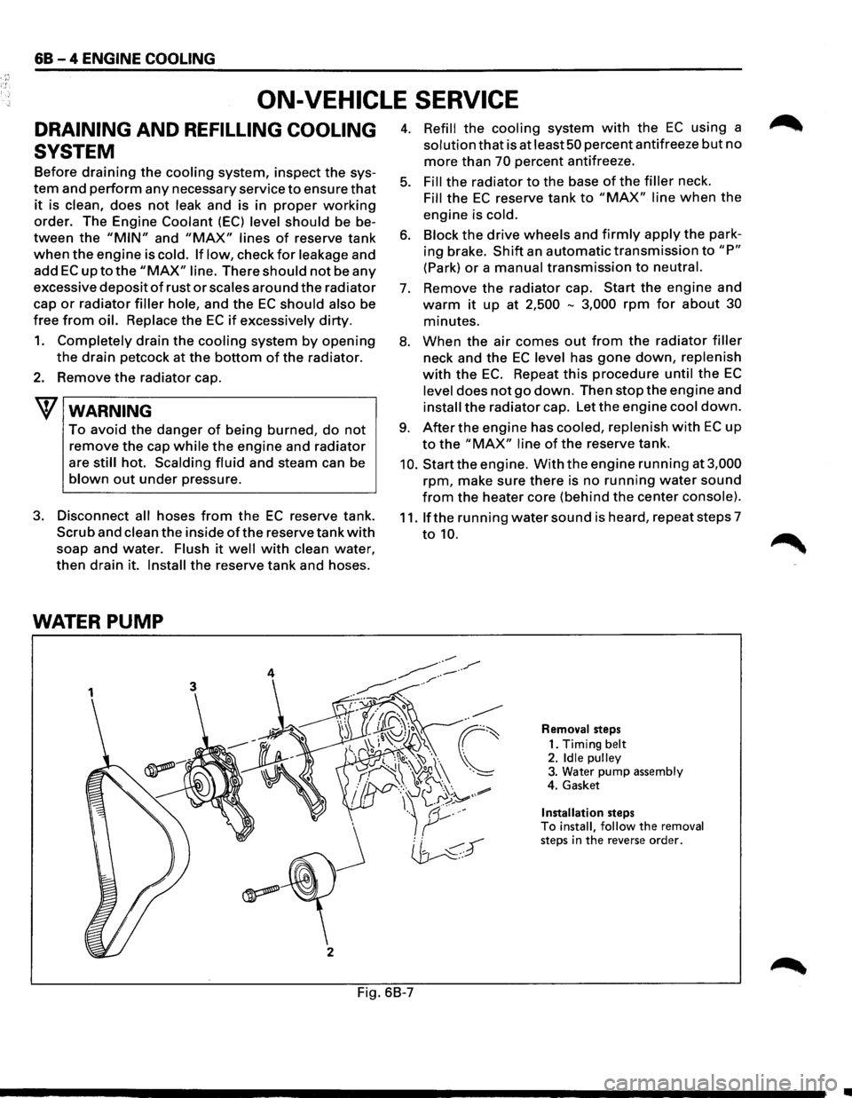
WATER PUMP
3
j
2
4. Refill the cooling system with the EC using a
solution that is at least 50 percent antifreeze but no
more than 70 percent antifreeze.
5. Fill the radiator to the base of the filler neck.
Fill the EC reserve tank to "MAX" line when the
engine is cold.
6. Block the drive wheels and firmly apply the park
ing brake.
Shift an automatic transmission to "P"
(Park) or a manual transmission to neutral.
7. Remove the radiator cap. Start the engine and
warm it up at 2,500 -3,000 rpm for about 30
minutes.
8. When the air comes out from the radiator filler
neck and the EC level has gone down, replenish
with the EC. Repeat this procedure until the EC
level does not go down. Then stop the engine and
install the radiator cap. Let the engine cool down.
9. After the engine has cooled, replenish with EC up
to the "MAX" line of the reserve tank.
10. Start the engine. With the engine running at 3,000
rpm, make sure there is no running water sound
from the heater core (behind the center console).
11. If the running water sound is heard, repeat steps 7
to 10.
Removal steps
1. Timing
belt 2. Idle pulley 3. Water pump assembly
4. Gasket
Installation steps To install, follow the removal steps in the reverse order.
Fig. 6B-7
•
Page 633 of 1928
EJ REMOVAL
Preparation
• Disconnect battery ground cable.
•
Drain coolant.
•
Radiator hose (on inlet pipe side)
1. Timing belt
• (Refer to Timing belt removal steps in Section
6A1, 6A2)
2. Idle pulley
3. Water pump assembly
4. Gasket
~ INSPECTION
Make necessary repair and parts replacement if ex
treme wear or damage is found during inspection.
Should any of the following problems occur, the
entire water pump assembly must be replaced.
•
Cracks in the Engine Coolant (EC) pump body
• EC leakage from the seal unit
• Play or abnormal noise in the bearing
• Cracks or corrosion in the impeller
8 INSTALLATION
4. Gasket
• Clean the mating surface of packing before
installation.
3. Water pump assembly
• Install coolant pump assembly and tighten
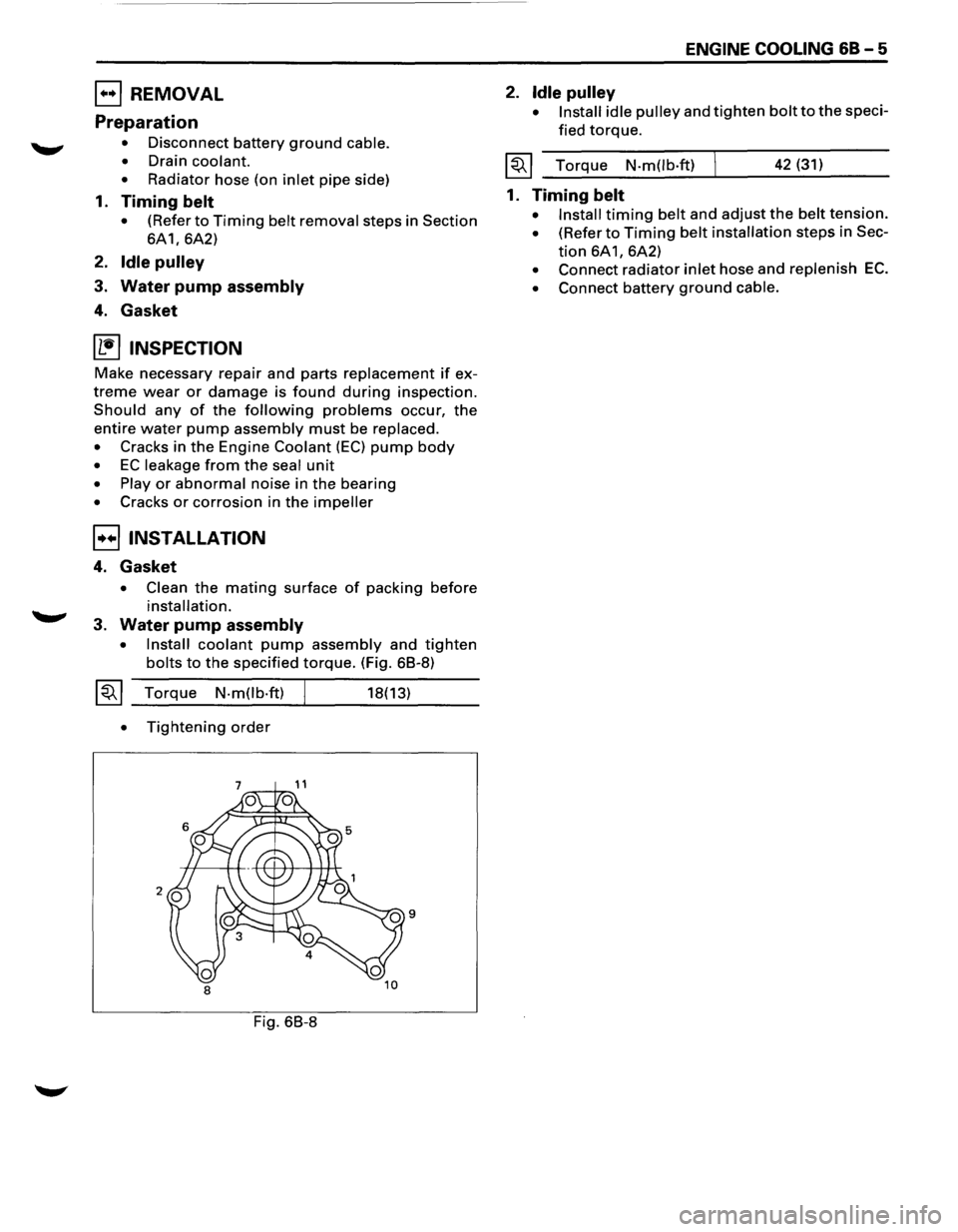
bolts to the specified torque. (Fig. 68-8)
~~~ Torque N-m(lb-ft)
•
Tightening order
Fig. 68-8
18(13)
ENGINE COOLING 68-5
2. Idle pulley
• Install idle pulley and tighten bolt to the speci
fied
torque.
~~~ Torque N-m(lb·ft) 42 (31)
1. Timing belt
• Install timing belt and adjust the belt tension.
• (Refer to Timing belt installation steps in Sec
tion 6A1, 6A2)
• Connect radiator inlet hose and replenish EC.
• Connect battery ground cable.