steering wheel adjustment ISUZU TROOPER 1995 Workshop Manual
[x] Cancel search | Manufacturer: ISUZU, Model Year: 1995, Model line: TROOPER, Model: ISUZU TROOPER 1995Pages: 1928
Page 3 of 1928
•:1
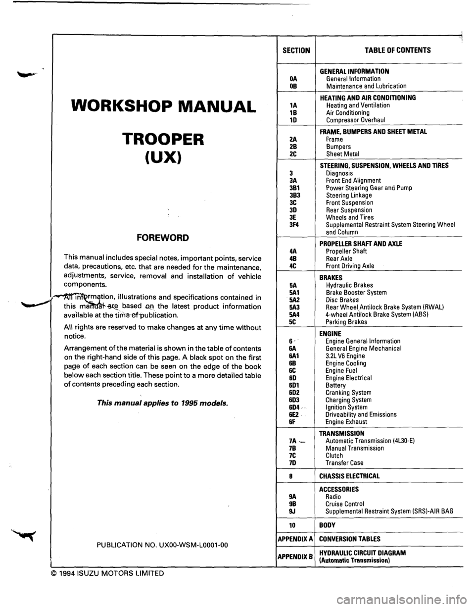
SECTION TABLE OF CONTENTS
. GENERAL INFORMATION OA General Information OB Maintenance and Lubrication
WORKSHOP MANUAL
HEATING AND AIR CONDITIONING 1A Heating and Ventilation
1B Air Conditioning 1D Compressor Overhaul
TROOPER
FRAME, BUMPERS AND SHEET METAL
2A Frame 2B Bumpers
(UX) 2C Sheet Metal
STEERING, SUSPENSION, WHEELS AND TIRES
3 Diagnosis 3A Front End Alignment 3B1 Power Steering Gear and Pump 3B3 Steering Linkage 3C Front Suspension 3D Rear Suspension 3E Wheels and Tires 3F4 Supplemental Restraint System Steering Wheel
FOREWORD and Column
PROPELLER SHAFT AND AXLE 4A Propeller Shaft This manual includes special notes, important points, service 4B Rear Axle
data, precautions, etc. that are needed for the maintenance, 4C Front Driving Axle
adjustments, service, removal and installation of vehicle BRAKES components. 5A Hydraulic Brakes
·~ m rmation, illustrations and specifications contained in 5A1 Brake Booster System
.. _,. 5A2 Disc Brakes ~ this ma. ~-based D.fl the latest product information 5A3 Rear Wheei_Antilock Brake System (RWAL)
available at the tirrHHrl·publication. 5A4 4-wheel Antilock Brake System (ABS)
5C Parking Brakes All rights are reserved to make changes at any time without ENGINE notice. 6· Engine General Information Arrangement of the material is shown in the table of contents &A General Engine Mechanical
on the right-hand side of this page. A black spot on the first 6A1 3.2L VB Engine
page of each section can be seen on the edge of the book &B Engine Cooling
6C Engine Fuel below each section title. These point to a more detailed table &D Engine Electrical of contents preceding each section. 6D1 Battery 6D2 Cranking System
This manual applies to 1995 models. 6D3 Charging System 6D4-Ignition System 6E2. Driveability and Emissions 6F Engine Exhaust
TRANSMISSION 7A-Automatic Transmission (4L30·E) 7B Manual Transmission 7C Clutch 7D Transfer Case
8 CHASSIS ELECTRICAL
ACCESSORIES 9A Radio 9B Cruise Control 9J Supplemental Restraint System (SRS)-AIR BAG
10 BODY
APPENDIX A CONVERSION TABLES PUBLICATION NO. UXOO-WSM-L0001-00
APPENDIXB HYDRAULIC CIRCUIT DIAGRAM (Automatic Transmission)
© 1994 ISUZU MOTORS LIMITED
Page 22 of 1928
OB-6 MAINTENANCE AND LUBRICATION
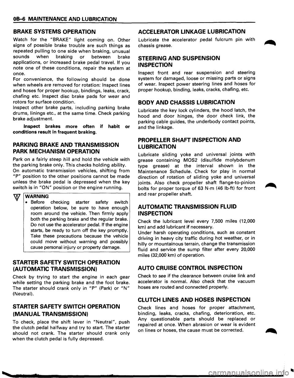
BRAKE SYSTEMS OPERATION
Watch for the "BRAKE" light coming on. Other
signs of possible brake trouble are such things as
repeated pulling to one side when braking, unusual
sounds
when braking or between brake
applications,
or increased brake pedal travel. If you
note one of these conditions, repair the system at
once.
For convenience, the
following should be done
when wheels are removed for rotation: Inspect lines
and hoses
for proper hookup, bindings, leaks, crack,
chafing etc.
Inspect disc brake pads for wear and
rotors
for surface condition.
Inspect other brake parts, including parking brake
drums, linings etc., at the same time. Check parking
brake adjustment.
Inspect brakes more often if habit or
conditions
result in frequent braking.
PARKING BRAKE AND TRANSMISSION
PARK MECHANISM OPERATION
Park on a fairly steep hill and hold the vehicle with
the parking brake only. This checks holding ability.
On
automatic transmission vehicles, shifting from
"P" position to the other positions cannot be made
unless
the brake pedal is depressed when the key
switch is in
"ON" position or the engine running.
WARNING
•
Before checking starter safety switch
operation below,
be sure to have enough
room around the
vehicle. Then firmly apply
both the parking brake and the regular brake.
Do not
use the accelerator pedal. If the engine
starts, be ready
to turn off the key promptly.
Take these precautions because the vehicle
could move
without warning and possibly
cause personal injury
or property damage.
STARTER SAFETY SWITCH OPERATION
(AUTOMATIC TRANSMISSION)
Check by trying to start the engine in each gear
while setting the parking brake and the foot brake.
The starter
should crank only in "P" (Park) or "N"
(Neutral).
STARTER SAFETY SWITCH OPERATION
(MANUAL TRANSMISSION)
To check, place the shift lever in "Neutral", push
the clutch pedal halfway and try to start. The starter
should not crank. The starter should crank only
when the clutch pedal is fully depressed.
ACCELERATOR LINKAGE LUBRICATION
Lubricate the accelerator pedal fulcrum pin with
chassis grease.
STEERING AND SUSPENSION
INSPECTION
Inspect front and rear suspension and steering
system
for damaged, loose or missing parts or signs
of wear. Inspect power steering lines and hoses for
proper hookup, binding, leaks, cracks, chafing, etc.
BODY AND CHASSIS LUBRICATION
Lubricate the key lock cylinders, the hood latch, the
hood and door hinges, the door check link, the
parking cable guides,
the underbody contact points,
and the linkage.
PROPELLER SHAFT INSPECTION AND
LUBRICATION
Lubricate sliding yoke and universal joints with
grease containing MOS2 (disulfide molybdenum
type grease) at the interval shown in the
Maintenance Schedule. Check for play in normal
direction of rotation of sliding yoke and universal
joints. Also check
propeller shaft flange-to-pinion
bolts for proper torque of 63 N·m (46 lb·ft) for front
and rear propeller shaft.
AUTOMATIC TRANSMISSION FLUID
INSPECTION
Check the lubricant level every 7,500 miles (12,000
km) and add lubricant
if necessary.
Under harsh operating conditions, such as constant
driving in heavy city traffic during
hot weather, or in
hilly or mountainous terrain, change the transmission
fluid and service the
sump filter after every 20,000
miles (32,000 km) of operation.
AUTO CRUISE CONTROL INSPECTION
Check to see if the clearance between cruise link and
accelerator is normal. Also check that the vacuum
hoses are routed and connected properly.
CLUTCH LINES AND HOSES INSPECTION
Check lines and hoses for proper attachment,
binding, leaks, cracks, chafing, deterioration, etc.
Any questionable parts should be replaced or
repaired at once. When abrasion or wear is evident
on lines or hoses, the cause must be corrected.
..
Page 122 of 1928
3-2 DIAGNOSIS
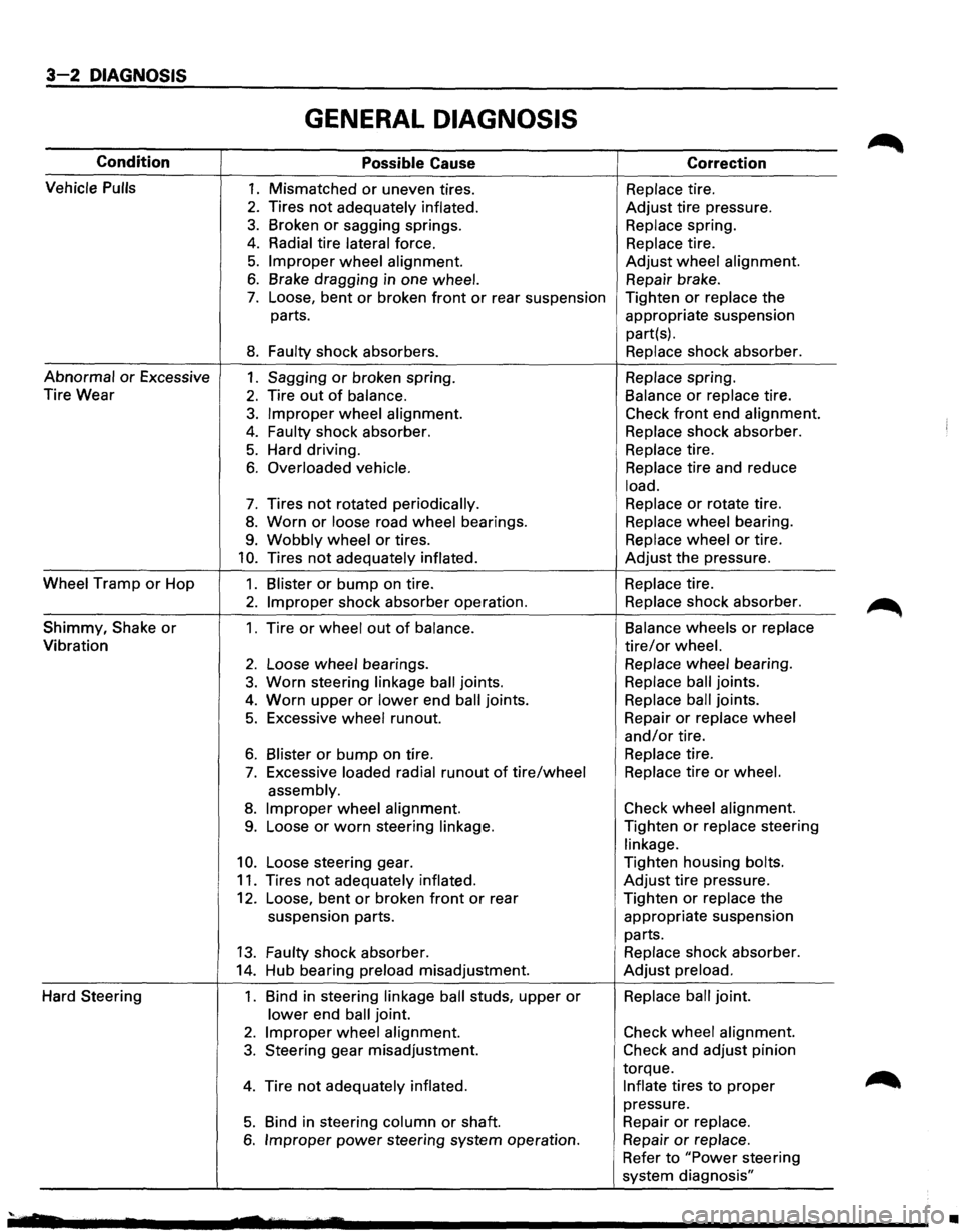
GENERAL DIAGNOSIS
Condition Possible Cause Correction
Vehicle
Pulls 1. Mismatched or uneven tires. Replace tire.
2. Tires not adequately inflated. Adjust tire pressure.
3. Broken or sagging springs. Replace spring.
4. Radial tire lateral force. Replace tire.
5. Improper wheel alignment. Adjust wheel alignment.
6. Brake dragging in one wheel. Repair brake.
7. Loose, bent or broken front or rear suspension Tighten or replace the
parts. appropriate suspension
part(s).
8. Faulty shock absorbers. Replace shock absorber.
Abnormal or Excessive 1. Sagging or broken spring. Replace spring.
Tire Wear
2. Tire out of balance. Balance or replace tire.
3. Improper wheel alignment. Check front end alignment.
4. Faulty shock absorber. Replace shock absorber.
5. Hard driving. Replace tire.
6. Overloaded vehicle. Replace tire
and reduce
load.
7. Tires not rotated periodically. Replace or rotate
tire.
8. Worn or loose road wheel bearings. Replace wheel bearing.
9. Wobbly wheel or tires. Replace wheel or tire.
10. Tires not adequately inflated. Adjust the pressure.
Wheel Tramp or Hop 1. Blister or bump on tire. Replace tire.
2. Improper shock absorber operation. Replace shock absorber.
Shimmy,
Shake or 1. Tire or wheel out of balance. Balance
wheels or replace
Vibration tire/or wheel.
2. Loose wheel bearings. Replace wheel bearing.
3. Worn steering linkage ball joints. Replace ball joints.
4. Worn upper or lower end ball joints. Replace ball joints.
5. Excessive wheel runout. Repair or replace
wheel
and/or tire.
6. Blister or bump on tire. Replace tire.
7. Excessive loaded radial runout of tire/wheel Replace tire or wheel.
assembly.
8. Improper wheel alignment. Check
wheel alignment.
9. Loose or worn steering linkage. Tighten or replace steering
linkage.
10. Loose steering gear. Tighten
housing bolts.
11. Tires not adequately inflated. Adjust tire pressure.
12. Loose, bent or broken front or rear Tighten or replace the
suspension parts. appropriate suspension
parts.
13. Faulty shock absorber. Replace shock absorber.
14. Hub bearing preload misadjustment. Adjust preload.
Hard Steering 1. Bind in steering linkage ball studs, upper or Replace ball joint.
lower end ball joint.
2. Improper wheel alignment. Check wheel alignment.
3. Steering gear misadjustment. Check and adjust pinion
torque.
4. Tire not adequately inflated. Inflate tires to proper
pressure.
5. Bind in steering column or shaft. Repair or replace.
6. Improper power steering
system operation. Repair or replace.
Refer to "Power steering
system diagnosis"
'· •
Page 123 of 1928
DIAGNOSIS 3-3
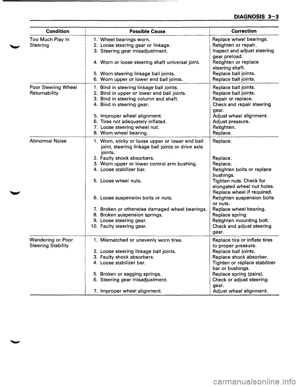
Condition Possible Cause Correction
Too
Much Play In 1. Wheel bearings worn. Replace wheel bearings.
Steering
2. Loose steering gear or linkage. Retighten or repair.
3. Steering
gear misadjustment. Inspect and adjust steering
gear preload.
4. Worn or loose steering shaft universal joint. Retighten or replace
steering shaft.
5. Worn steering linkage ball joints. Replace ball joints.
6. Worn upper or lower end ball joints. Replace ball joints.
Poor Steering
Wheel 1. Bind in steering linkage ball joints. Replace ball joints.
Returnability 2. Bind
in upper or lower end ball joints. Replace ball joints.
3. Bind
in steering column and shaft. Repair
or replace.
4. Bind in steering gear. Check and repair steering
gear.
5. Improper wheel alignment. Adjust wheel alignment.
6. Tires not adequately
inflated. Adjust
pressure.
7. Loose steering wheel nut. Retighten.
8. Worn wheel bearing.
Replace.
Abnormal Noise
1. Worn, sticky or loose upper or lower end ball Replace.
joint, steering linkage
ball joints or drive axle
joints.
2. Faulty shock absorbers.
Replace.
3. Worn upper or lower control arm bushing.
Replace.
4. Loose stabilizer bar. Retighten bolts or replace
bushings.
5. Loose wheel nuts. Tighten nuts. Check for
elongated wheel nut holes.
Replace
wheel if required.
6. Loose suspension bolts or nuts. Retighten suspension bolts
or nuts.
7. Broken or otherwise damaged wheel bearings. Replace wheel bearing.
8. Broken suspension springs. Replace spring.
9. Loose steering gear. Retighten mounting bolt.
10. Faulty steering gear. Check and adjust steering
gear.
Wandering
or Poor 1. Mismatched or unevenly worn tires. Replace tire or inflate tires
Steering
Stability to proper pressure.
2. Loose steering linkage ball joints. Replace ball joints.
3. Faulty shock absorbers. Replace shock absorber.
4. Loose stabilizer bar. Tighten or replace stabilizer
bar or bushings.
5. Broken or sagging springs. Replace spring (pairs).
6. Steering gear misadjustment. Check or adjust steering
gear.
7. Improper wheel alignment.
Adjust wheel alignment.
Page 125 of 1928
DIAGNOSIS 3-5
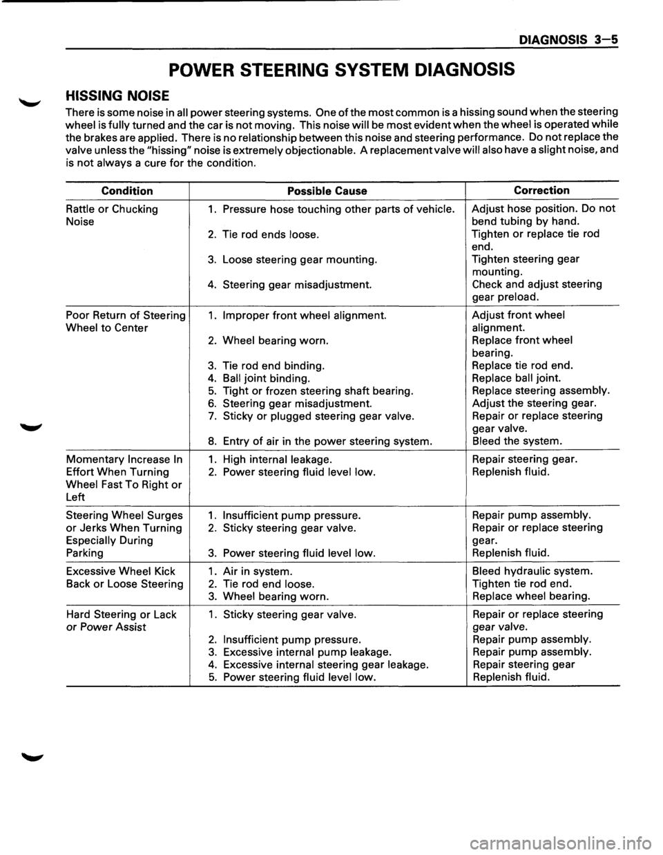
POWER STEERING SYSTEM DIAGNOSIS
HISSING NOISE
There is some noise in all power steering systems. One of the most common is a hissing sound when the steering
wheel is fully turned and the car is not moving. This noise will be most evident when the wheel is operated while
the brakes are applied. There is no relationship between this noise and steering performance. Do not replace the
valve unless the "hissing" noise is extremely objectionable. A replacement valve will also have a slight noise, and
is
not always a cure for the condition.
Condition
Possible Cause Correction
Rattle or Chucking 1. Pressure
hose touching other parts of vehicle. Adjust hose position. Do not
Noise bend
tubing by hand.
2. Tie rod ends loose. Tighten or replace tie rod
end.
3. Loose steering gear mounting. Tighten
steering gear
mounting.
4. Steering gear misadjustment. Check and adjust steering
gear
preload.
Poor Return of Steering 1. Improper front wheel alignment. Adjust front wheel
Wheel
to Center alignment.
2. Wheel bearing worn. Replace front wheel
bearing.
3. Tie rod end binding. Replace tie rod end.
4. Ball joint binding. Replace ball joint.
5. Tight or frozen steering shaft bearing. Replace steering assembly.
6. Steering gear misadjustment. Adjust the steering gear.
7. Sticky or plugged steering gear valve. Repair or replace steering
gear
valve.
8. Entry of air in the power steering system. Bleed the system.
Momentary Increase In 1. High internal leakage. Repair steering gear.
Effort When Turning
2. Power steering fluid level low. Replenish
fluid.
Wheel
Fast To Right or
Left
Steering
Wheel Surges 1. Insufficient pump pressure. Repair pump assembly.
or Jerks
When Turning 2. Sticky steering gear valve. Repair or replace steering
Especially During gear.
Parking
3. Power steering fluid level low. Replenish
fluid.
Excessive Wheel Kick 1. Air in system. Bleed hydraulic system.
Back
or Loose Steering 2. Tie rod end loose. Tighten tie rod end.
3. Wheel bearing worn. Replace wheel bearing.
Hard Steering
or Lack 1. Sticky steering gear valve. Repair or replace steering
or Power Assist gear valve.
2. Insufficient pump pressure.
Repair pump assembly.
3. Excessive internal pump leakage. Repair
pump assembly.
4. Excessive internal steering gear leakage. Repair steering gear
5. Power steering fluid level low. Replenish
fluid.
Page 130 of 1928
3-10 DIAGNOSIS
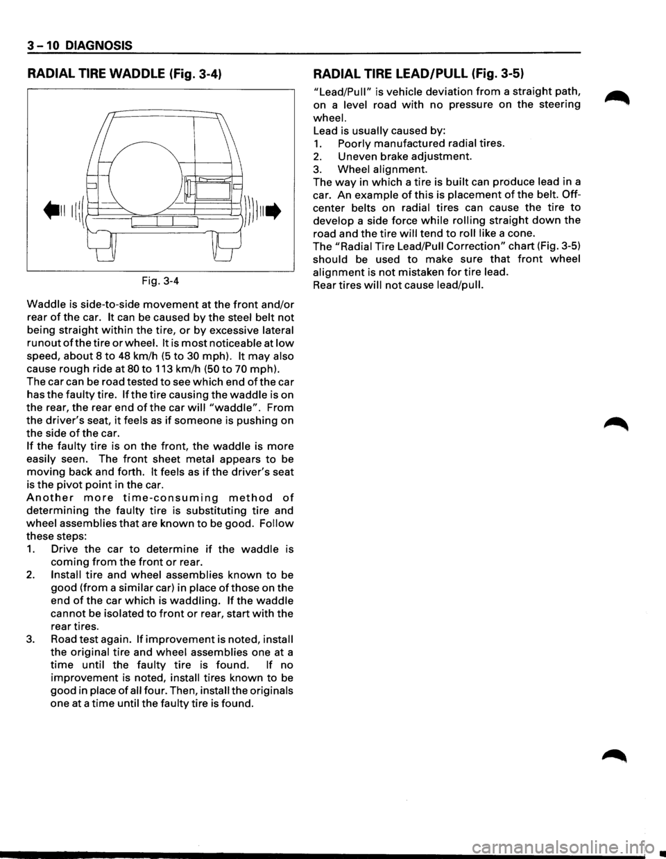
RADIAL TIRE WADDLE (Fig. 3-4)
Fig. 3-4
Waddle is side-to-side
movement at the front and/or
rear of the car. It can be caused by the steel belt not
being straight within the tire, or by excessive lateral
runout of the tire or wheel. It is most noticeable at low
speed, about 8 to 48 km/h (5 to 30 mph). It may also
cause
rough ride at 80 to 113 km/h (50 to 70 mph).
The car can be road tested
to see which end of the car
has
the faulty tire. If the tire causing the waddle is on
the rear, the rear end
of the car will "waddle". From
the
driver's seat, it feels as if someone is pushing on
the side
of the car.
If the faulty tire is on the front, the waddle is more
easily seen. The front sheet metal appears to be
moving back and forth. It feels as if the driver's seat
is
the pivot point in the car.
Another more time-consuming method of
determining the faulty tire is substituting tire and
wheel assemblies
that are known to be good. Follow
these steps:
1. Drive the car to determine if the waddle is
coming from the front or rear.
2. Install tire and wheel assemblies known to be
good (from a similar car) in place ofthose on the
end
of the car which is waddling. If the waddle
cannot be isolated to front or rear, start with the
rear tires.
3. Road test again. If improvement is noted, install
the original tire and wheel assemblies one at a
time until the faulty tire is found. If no
improvement is noted, install tires known to be
good in place of all four. Then, install the originals
one at a
time until the faulty tire is found.
RADIAL TIRE LEAD/PULL (Fig. 3-5)
"Lead/Pull" is vehicle deviation from a straight path,
on a level road
with no pressure on the steering
wheel.
Lead is usually caused by:
1. Poorly manufactured radial tires.
2. Uneven brake adjustment.
3. Wheel alignment.
The
way in which a tire is built can produce lead in a
car.
An example of this is placement of the belt. Off
center belts on radial tires can cause the tire to
develop a side force while rolling straight down the
road and the tire will tend to roll like a cone.
The
"Radial Tire Lead/Pull Correction" chart (Fig. 3-5)
should be used to make sure that front wheel
alignment is not mistaken for tire lead.
Rear
tires will not cause lead/pull.
II
Page 133 of 1928
FRONT END ALIGNMENT 3A-1
SECTION3A
FRONT END ALIGNMENT
CAUTION:
When fasteners are removed, always reinstall them at the same location from which they were removed. If
a fastener needs to be replaced, use the correct part number fastener for that application. If the correct part
number fastener is not available, a fastener of equal size and strength (or stronger) may be used. Fasteners
that are not reused, and those requiring thread locking compound will be called out. The correcttorque value
must be used when installing fasteners that require it. If the above conditions are not followed, parts or
system damage could result.
CONTENTS
General Description ................................ 3A-1
Camber Adjustment ............................. 3A-4
Definition of Terms .............................. 3A·2 Toe-in Adjustment ............................... 3A-5
On-Vehicle Service ................................. 3A-3 Maximum Steering Angle Adjustment ....... 3A-5
Inspection ......................................... 3A-3 Main Data and Specifications ..................... 3A-6
Trim Height Adjustment ........................ 3A-3 General Specifications .......................... 3A-6
Caster
Adjustment ............................... 3A-3 Torque Specifications ........................... 3A-6
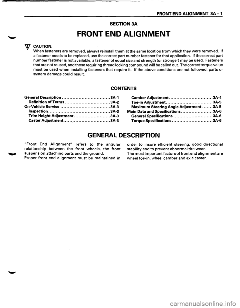
GENERAL DESCRIPTION
"Front End Alignment" refers to the angular
relationship between the front wheels, the front
suspension attaching parts and the ground.
Proper front end alignment must be maintained in
order to insure efficient steering, good directional
stability and to prevent abnormal tire wear.
The
most important factors of front end alignment are
wheel toe-in, wheel camber and axle caster.
Page 135 of 1928
FRONT END ALIGNMENT 3A-3
ON-VEHICLE SERVICE
INSPECTION
Before making any adjustments affecting caster,
camber or toe-in, the following front end inspection
should be made.
I L•IINSPECT
1. Tires for proper inflation pressure. Refer to
"Wheels and Tires" in section 3E.
2. Front wheel bearings for proper adjustment.
Refer to "Front Wheel Drive" in section 4C.
3. Ball joints, tie rod ends and relay rods. If
excessive looseness is noted, correct before
adjusting. Refer
to "Steering Linkage" in section
3B3.
4. Wheel and tires for run-out. Refer to "Wheels
and Tires" in section 3E.
5. Trim height. If not within specifications, the
correction
must be made before adjusting caster.
6. Steering gear for looseness at the frame.
7. Shock absorbers for leaks or any noticeable
noise.
Refer
to "Front Suspension" in section 3C.
8. Control arms or stabilizer bar attachment for
looseness. Refer to "Front Suspension" in section
3C.
9. Alignment equipment. Follow the manufacturer's
instructions.
10. Level of the vehicle. The vehicle must be on a
level surface.
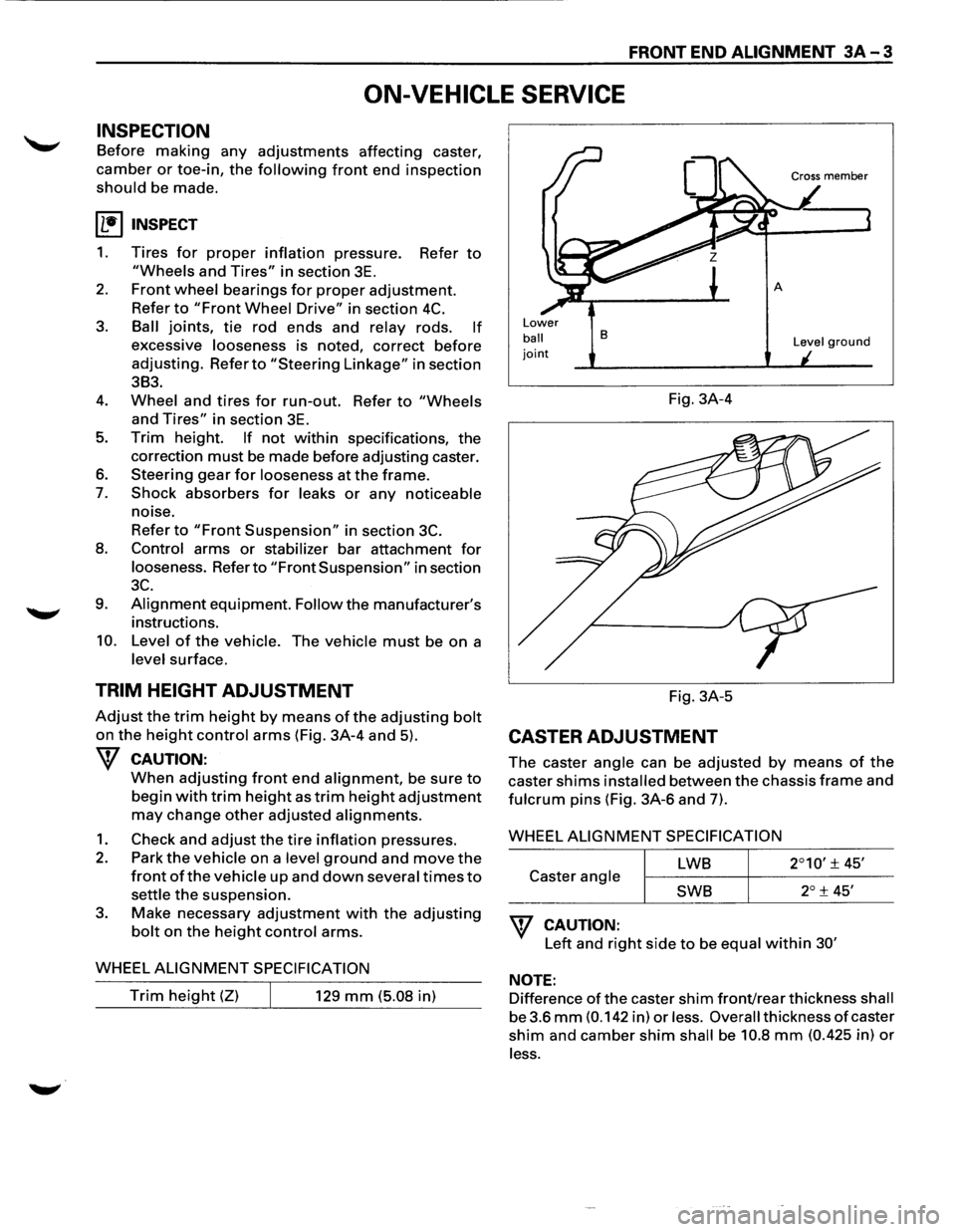
TRIM HEIGHT ADJUSTMENT
Adjust the trim height by means of the adjusting bolt
on the height control arms (Fig. 3A-4 and 5).
W CAUTION:
When adjusting front end alignment, be sure to
begin with trim height as trim height adjustment
may change other adjusted alignments.
1. Check and adjust the tire inflation pressures.
2. Park the vehicle on a level ground and move the
front of the vehicle up and down several times to
settle the suspension.
3. Make necessary adjustment with the adjusting
bolt on the height control arms.
WHEEL
ALIGNMENT SPECIFICATION
Trim height (Z) 129 mm (5.08 in)
Lower
ball joint
B
Fig. 3A-4
Fig. 3A-5
CASTER ADJUSTMENT
Level ground
The caster angle can be adjusted by means of the
caster shims installed between the chassis frame and
fulcrum pins (Fig. 3A-6 and 7).
WHEEL
ALIGNMENT SPECIFICATION
LWB
Caster angle
SWB
W CAUTION:
Left and right side to be equal within 30'
NOTE:
Difference of the caster shim front/rear thickness shall
be 3.6
mm (0.142 in) or less. Overall thickness of caster
shim and camber shim shall be 10.8 mm (0.425 in) or
less.
Page 137 of 1928
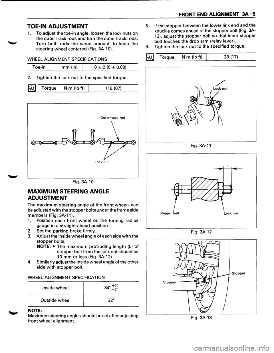
TOE-IN ADJUSTMENT
1. To adjust the toe-in angle, loosen the lock nuts on
the outer track rods and turn the outer track rods.
Turn both rods the same amount, to keep the
steering
wheel centered (Fig. 3A-1 0).
WHEEL ALIGNMENT SPECIFICATIONS
Toe-in mm (in) I 0 ± 2 (0 ± 0.08)
2. Tighten the lock nut to the specified torque.
~~~ Torque N·m (lb·ft) 118 (87)
Outer track rod
Lock nut
Fig. 3A-10
MAXIMUM STEERING ANGLE
ADJUSTMENT
The maximum steering angle of the front wheels can
be adjusted
with the stopper bolts under the frame side
members (Fig. 3A-11 ).
1. Position each front wheel on the turning radius
gauge in a straight-ahead position.
2. Set the parking brake firmly.
3. Adjust the inside wheel angle of each side with the
stopper
bolts.
NOTE: • The maximum protruding length (L) of
stopper bolt from the lock nut should be
10 mm or less (Fig. 3A-12)
4. Similarly adjust the inside wheel angle of the other
side
with stopper bolt.
WHEEL ALIGNMENT SPECIFICATION
Inside wheel
34° ~~:
Outside wheel 32°
NOTE:
Maximum steering angles should be set after adjusting
front wheel alignment.
FRONT END ALIGNMENT 3A-5
5. If the stopper between the lower link end and the
knuckle comes ahead of the stopper bolt (Fig. 3A-
13), adjust the stopper
bolt so that inner stopper
bolt touches the drop arm (relay lever).
6. Tighten the lock nut to the specified torque.
~~~ Torque N·m (lb·ft) 23 (17)
Fig. 3A-11
L
Stopper bolt Lock nut
Fig. 3A-12
Stopper
Fig. 3A-13
Page 139 of 1928
POWER STEERING GEAR AND PUMP 381 -1
SECTION 381
POWER STEERING GEAR AND PUMP
w CAUTION:
When fasteners are removed, always reinstall them at the same location from which they were removed.
If a fastener needs to be replaced, use the correct part number fastener for that application. If the correct
part
number fastener is not available, a fastener of equal size and strength (or stronger) may be used.
Fasteners
that are not reused, and those requiring thread locking compound, will be called out. The correct
torque value must be used when installing fasteners that require it. If the above conditions are not
followed, parts or system damage could result.
CONTENTS
General Description ............................ 3B1- 1
Steering Wheel Free Play Adjustment .... 3B1-5
Power Steering
Gear........................ 3B1-1
Steering Gear ................................ 3B1-6
Hydraulic Pump .............................. 3B1- 1
Power Steering Pump ...................... 3B1-8
Pressure Switch
............................. 3B1-1
Unit Repair ...................................... 3B1- 9
Power Steering System Test
................. 3B1-3
Steering Gear ................................ 3B1-9
On-Vehicle Service ............................. 3B1- 4
Power Steering Pump ...................... 3B1-14
Maintenance
................................. 3B1- 4
Main Data and Specifications ................ 3B1-17
Fluid Level .................................... 3B1- 4 General Specifications ...................... 3B1-17
Bleeding The Power Steering System .... 3B1-4
Torque Specifications ....................... 3B1-17
Bleeding Procedure ......................... 3B1-4 Special Tools.................................... 3B1-18
Flushing The Power Steering System .... 3B1-4
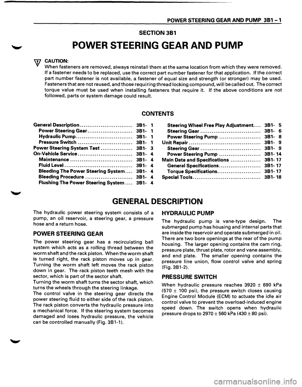
GENERAL DESCRIPTION
The hydraulic power steering system consists of a
pump, an oil reservoir, a steering gear, a pressure
hose and a return hose.
POWER STEERING GEAR
The power steering gear has a recirculating ball
system which acts as a rolling thread between the
worm shaft and the rack piston. When the worm shaft
is
turned right, the rack piston moves up in gear.
Turning the worm shaft left moves the rack piston
down in gear. The rack piston teeth mesh with the
sector, which is part ofthe sector shaft.
Turning the worm shaft turns the sector shaft, which
turns the wheels through the steering linkage.
The control valve in the steering gear directs the
power steering fluid to either side of the rack piston.
The rack
piston converts the hydraulic pressure into
a mechanical force. If the steering system becomes
damaged and loses hydraulic pressure, the vehicle
can be controlled manually (Fig. 381-1).
HYDRAULIC PUMP
The hydraulic pump is vane-type design. The
submerged pump has housing and internal parts that
are inside the reservoir and operate submerged in oil.
There are two bore openings at the rear of the pump
housing. The larger opening contains the cam ring,
pressure
plate, thrust plate, rotor and vane assembly,
and end plate. The smaller opening contains the
pressure
line union, flow control valve and spring
(Fig. 381-2).
PRESSURE SWITCH
When hydraulic pressure reaches 3920 ± 690 kPa
(570 ± 100 psi), the pressure switch closes causing
Engine
Control Module (ECM) to actuate the idle air
control valve to prevent the overload-induced engine
speed down. The switch opens
when hydraulic
pressure drops to 2970 ± 560 kPa (430 ± 80 psi).