recommended oil ISUZU TROOPER 1995 Workshop Manual
[x] Cancel search | Manufacturer: ISUZU, Model Year: 1995, Model line: TROOPER, Model: ISUZU TROOPER 1995Pages: 1928
Page 5 of 1928
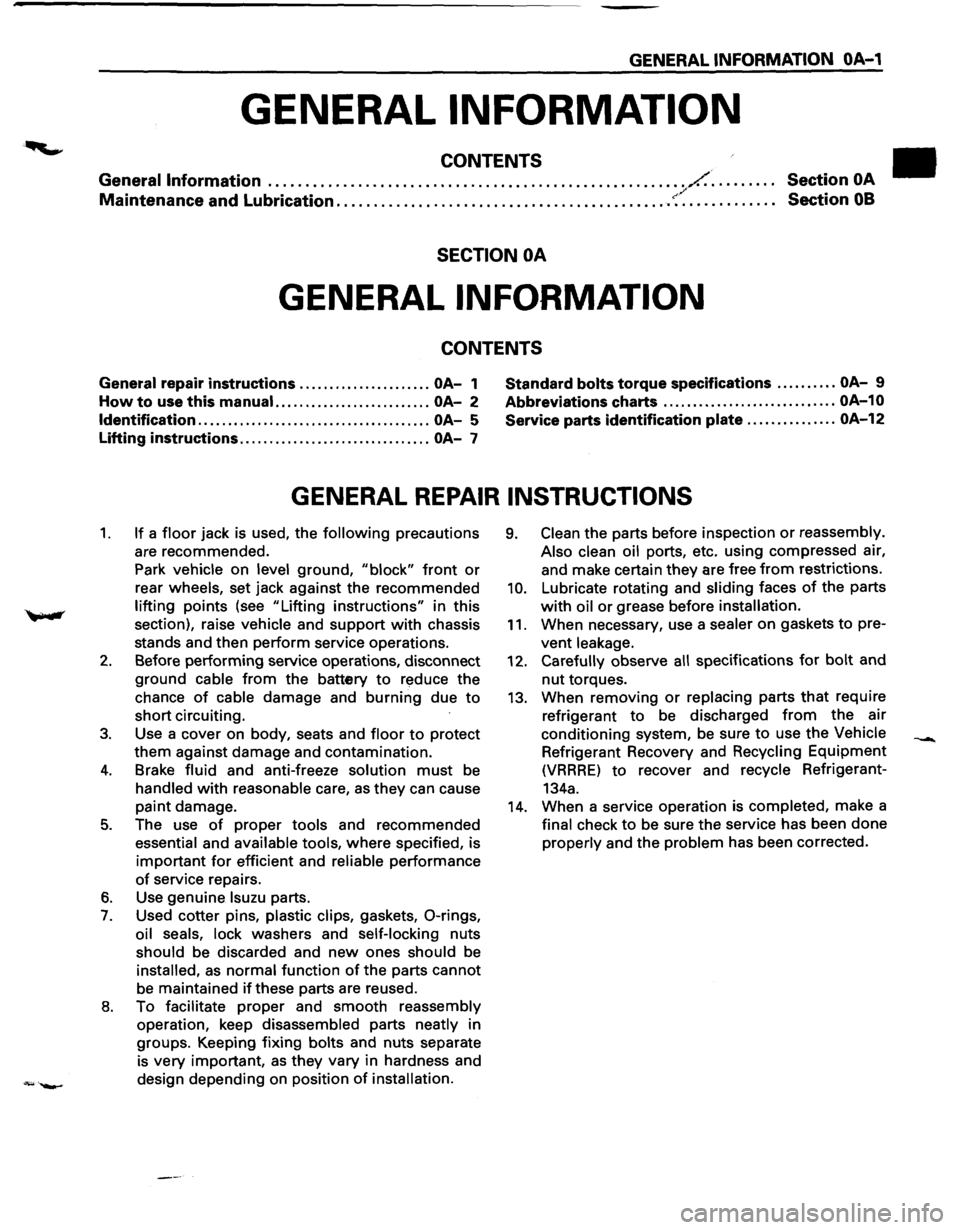
GENERAL INFORMATION OA-1
GENERAL INFORMATION
CONTENTS
General Information ........................................................ /.. . . . . . . . . Section OA / Maintenance and Lubrication ............................................. ~·. . . . . . . . . . . . . Section 08
SECTION OA
GENERAL INFORMATION
CONTENTS
General repair instructions ...................... OA-1 Standard bolts torque
specifications .......... OA-9
How to use this manual. ......................... OA-2 Abbreviations
charts ............................. OA-10
Identification
....................................... OA-5 Service
parts identification plate ............... OA-12
Lifting instructions ................................ OA-7
GENERAL REPAIR INSTRUCTIONS
1. If a floor jack is used, the following precautions
are recommended.
Park
vehicle on level ground, "block" front or
rear wheels, set jack against the recommended
lifting points (see "Lifting instructions" in this
section), raise
vehicle and support with chassis
stands and then perform service operations.
2. Before performing service operations, disconnect
ground
cable from the battery to reduce the
chance
of cable damage and burning due to
short circuiting.
3. Use a cover on body, seats and floor to protect
them against damage and contamination.
4. Brake fluid and anti-freeze solution must be
handled with reasonable care, as they can cause
paint damage.
5. The use of proper tools and recommended
essential and available tools, where specified, is
important for efficient and reliable performance
of service repairs.
6. Use genuine lsuzu parts.
7. Used cotter pins, plastic clips, gaskets, 0-rings,
oil seals, lock washers and self-locking nuts
should be discarded and new ones should be
installed, as normal function of the parts cannot
be maintained
if these parts are reused.
8. To facilitate proper and smooth reassembly
operation, keep disassembled parts neatly in
groups. Keeping fixing
bolts and nuts separate
is
very important, as they vary in hardness and
design depending on position
of installation.
9. Clean the parts before inspection or reassembly.
Also clean oil
ports, etc. using compressed air,
and make certain
they are free from restrictions.
10. Lubricate rotating and sliding faces of the parts
with oil or grease before installation.
11. When necessary, use a sealer on gaskets to pre
vent leakage.
12. Carefully observe all specifications for bolt and
nut torques.
13. When removing or replacing parts that require
refrigerant
to be discharged from the air
conditioning system, be sure
to use the Vehicle
Refrigerant Recovery and Recycling Equipment
(VRRRE) to recover and recycle Refrigerant-
134a.
14. When a service operation is completed, make a
final check to be sure the service has been done
properly and the problem has been corrected.
Page 17 of 1928
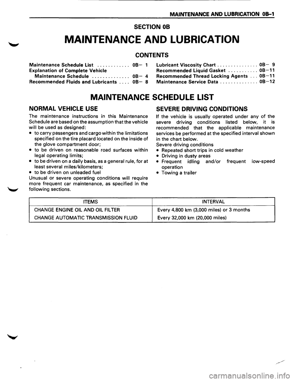
MAINTENANCE AND LUBRICATION OB-1
SECTION 08
MAINTENANCE AND LUBRICATION
CONTENTS
Maintenance Schedule List . . . . . . . . . . . . 08-1
Explanation of Complete Vehicle
Mai-ntenance Schedule . . . . . . . . . . . . . . 08-4
Recommended
Fluids and Lubricants . . . . 08-8
Lubricant Viscosity Chart ............... 08-9
Recommended Liquid Gasket
........... 08-11
Recommended Thread Locking Agents ... 08-11
Maintenance Service Data .............. 08-12
MAINTENANCE SCHEDULE LIST
NORMAL VEHICLE USE
The maintenance instructions in this Maintenance
Schedule are based on the assumption that the vehicle
will
be used as designed:
• to carry passengers and cargo within the limitations
specified on the tire placard located on the inside of
the glove compartment door;
• to be driven on reasonable road surfaces within
legal operating limits;
•
to be driven on a daily basis, as a general rule, for at
least several miles/kilometers;
•
to be driven on unleaded fuel
Unusual
or severe operating conditions will require
more frequent car maintenance,
as specified in the
following sections.
ITEMS
CHANGE ENGINE OIL AND OIL FIL TEA
CHANGE AUTOMATIC TRANSMISSION FLUID
SEVERE DRIVING CONDITIONS
If the vehicle is usually operated under any of the
severe driving conditions
listed below, it is
recommended that the
applicable maintenance
services be performed at the specified
interval shown
in the chart
below.
Severe driving conditions
• Repeated short trips in cold weather
• Driving in dusty areas
• Frequent idling and/or frequent low-speed
operation
• Towing a trailer
INTERVAL
Every 4,800 km (3,000 miles) or 3 months
Every
32,000 km (20,000 miles)
Page 18 of 1928
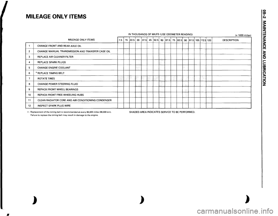
MILEAGE
ONL
V
ITEMS MILEAGE
ONLY
ITEMS
7.5
1
CHANGE
FRONT
AND
REAR AXLE
OIL
2
CHANGE
MANUAL
TRANSMISSION
AND
TRANSFER CASE
OIL
3
REPLACE AIR
CLEANER FILTER
4
REPLACE SPARK PLUGS
5
CHANGE ENGINE
COOLANT
6
*REPLACE
TIMING
BELT
7
ROT
ATE
TIRES
8
CHANGE
POWER STEERING FLUID
9
REPACK FRONT
WHEEL
BEARINGS
10
REPACK FRONT
FREE-WHEELING HUBS
11
CLEAN
RADIATOR
CORE
AND
AIR CONDITIONING CONDENSER
12
INSPECT SPARK PLUG WIRE
'
-----
* : Replacement
of the
timing
belt
is recommended
at every
60,000
miles
(96,000
km).
Failure
to replace
the timing
belt
may
result
in damage to the engine.
)
•
IN THOUSANDS
OF
MILES
(USE
ODOMETER
READING)
15 22.5
30
37.5 45 52.5
60
67.5
75
82.5
90
97.5
'
-
'---
~--·-L....
SHADED AREA
INDICATES SERVICE TO
BE
PERFORMED.
)
105
112.5
120 '-------
(x 1000
miles)
DESCRIPTION ------
)
0 ~ s: l> ~ z l> z 0 m l> z c rc m :a c; ~ 0 2
Page 21 of 1928
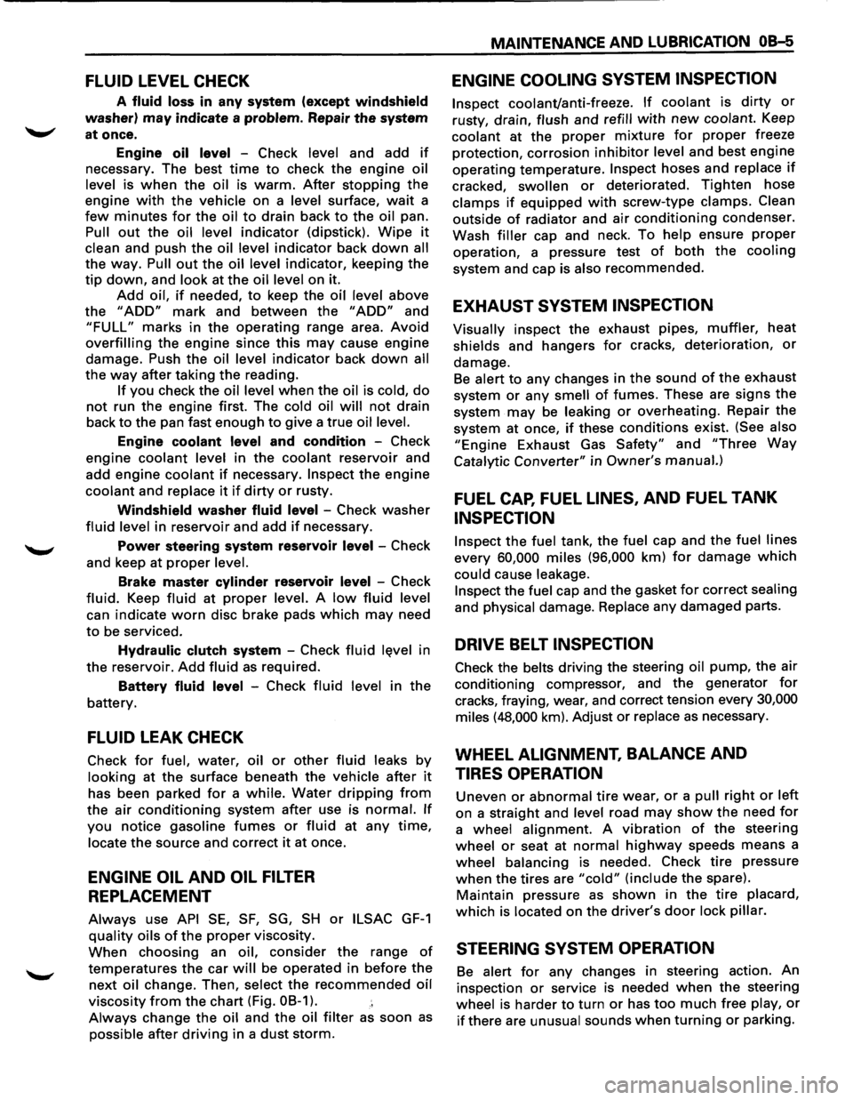
FLUID LEVEL CHECK
A fluid loss in any system (except windshield
washer) may indicate a problem. Repair the system
at once.
Engine
oil level -Check level and add if
necessary. The best time to check the engine oil
level is
when the oil is warm. After stopping the
engine with the vehicle on a level surface, wait a
few minutes for the oil to drain back to the oil pan.
Pull
out the oil level indicator (dipstick). Wipe it
clean and push the oil level indicator back down all
the
way. Pull out the oil level indicator, keeping the
tip down, and look at the oil level on it.
Add oil, if needed, to keep the oil level above
the
"ADD" mark and between the "ADD" and
"FULL" marks in the operating range area. Avoid
overfilling the engine since this may cause engine
damage. Push
the oil level indicator back down all
the
way after taking the reading.
If you check the oil level when the oil is cold, do
not run the engine first. The cold oil will not drain
back
to the pan fast enough to give a true oil level.
Engine coolant level and condition -Check
engine coolant level in the coolant reservoir and
add engine
coolant if necessary. Inspect the engine
coolant and replace it if dirty or rusty.
Windshield washer fluid level -Check washer
fluid level in reservoir and add if necessary.
Power steering system reservoir level-Check
and keep at
proper level.
Brake master cylinder reservoir level -Check
fluid. Keep fluid at proper level. A low fluid level
can indicate
worn disc brake pads which may need
to be serviced.
Hydraulic clutch system -Check fluid l~vel in
the reservoir.
Add fluid as required.
Battery fluid level -Check fluid level in the
battery.
FLUID LEAK CHECK
Check for fuel, water, oil or other fluid leaks by
looking at the surface beneath the vehicle after it
has been parked for a while. Water dripping from
the air conditioning system after use is normal. If
you notice gasoline fumes or fluid at any time,
locate the source and correct it at once.
ENGINE OIL AND OIL FILTER
REPLACEMENT
Always use API SE, SF, SG, SH or ILSAC GF-1
quality oils of the proper viscosity.
When choosing an oil, consider the range of
temperatures the car will be operated in before the
next oil change. Then, select the recommended oil
viscosity
from the chart (Fig. OB-1).
Always change the oil and the oil filter as soon as
possible after driving in a dust storm.
MAINTENANCE AND LUBRICATION OB-5
ENGINE COOLING SYSTEM INSPECTION
Inspect coolant/anti-freeze. If coolant is dirty or
rusty, drain, flush and refill with new coolant. Keep
coolant at the proper mixture for proper freeze
protection,
corrosion inhibitor level and best engine
operating temperature.
Inspect hoses and replace if
cracked, swollen or deteriorated. Tighten hose
clamps if equipped with screw-type clamps. Clean
outside of radiator and air conditioning condenser.
Wash
filler cap and neck. To help ensure proper
operation, a pressure test of both the cooling
system and cap is also recommended.
EXHAUST SYSTEM INSPECTION
Visually inspect the exhaust pipes, muffler, heat
shields and hangers
for cracks, deterioration, or
damage.
Be alert to any changes in the sound of the exhaust
system
or any smell of fumes. These are signs the
system may be leaking or overheating. Repair the
system at once,
if these conditions exist. (See also
"Engine Exhaust Gas Safety" and "Three Way
Catalytic Converter" in Owner's manual.)
FUEL CAP, FUEL LINES, AND FUEL TANK
INSPECTION
Inspect the fuel tank, the fuel cap and the fuel lines
every
60,000 miles (96,000 km) for damage which
could cause leakage.
Inspect the fuel cap and the gasket for correct sealing
and physical damage. Replace any damaged parts.
DRIVE BELT INSPECTION
Check the belts driving the steering oil pump, the air
conditioning compressor, and the generator
for
cracks, fraying, wear, and correct tension every 30,000
miles (48,000 km). Adjust or replace as necessary.
WHEEL ALIGNMENT, BALANCE AND
TIRES OPERATION
Uneven or abnormal tire wear, or a pull right or left
on a straight and level road may show the need for
a wheel alignment. A vibration of the steering
wheel or seat at normal highway speeds means a
wheel balancing is needed. Check tire pressure
when the tires are "cold" (include the spare).
Maintain pressure as shown in the tire placard,
which is located on the driver's door lock pillar.
STEERING SYSTEM OPERATION
Be alert for any changes in steering action. An
inspection
or service is needed when the steering
wheel is harder
to turn or has too much free play, or
if there are unusual sounds when turning or parking.
Page 24 of 1928
OB-8 MAINTENANCE AND LUBRICATION
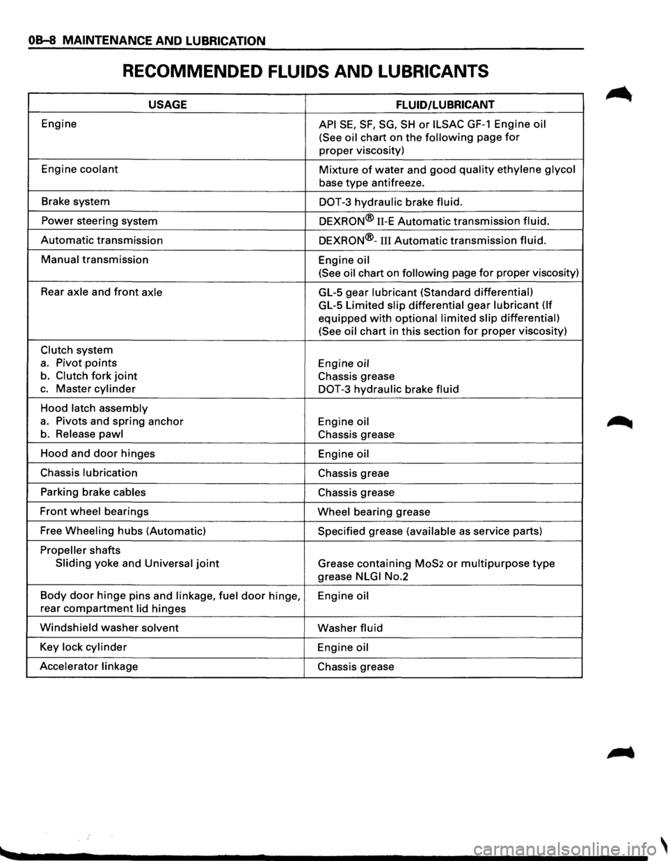
RECOMMENDED FLUIDS AND LUBRICANTS
USAGE FLUID/LUBRICANT
Engine API SE, SF, SG, SH or ILSAC GF-1 Engine oil
(See oil
chart on the following page for
proper viscosity)
Engine
coolant Mixture of water and good quality ethylene glycol
base type antifreeze.
Brake system
DOT-3 hydraulic brake fluid.
Power steering system
DEXRON® 11-E Automatic transmission fluid.
Automatic transmission DEXRON®-III Automatic transmission fluid.
Manual transmission
Engine oil
(See oil
chart on following page for proper viscosity)
Rear
axle and front axle GL-5 gear lubricant (Standard differential)
GL-5 Limited slip differential gear lubricant (If
equipped with optional limited slip differential)
(See oil
chart in this section for proper viscosity)
Clutch system
a. Pivot points Engine oil
b. Clutch fork joint Chassis grease
c. Master cylinder DOT-3 hydraulic brake fluid
Hood latch assembly
a. Pivots and spring anchor
Engine oil
b. Release pawl Chassis grease
Hood and
door hinges
Engine oil
Chassis lubrication Chassis greae
Parking brake
cables Chassis grease
Front wheel bearings Wheel bearing grease
Free
Wheeling hubs (Automatic) Specified grease (available as service parts)
Propeller shafts
Sliding yoke and Universal joint Grease containing MoS2 or multipurpose type
grease NLGI No.2
Body
door hinge pins and linkage, fuel door hinge,
Engine oil
rear compartment lid hinges
Windshield washer solvent Washer fluid
Key lock cylinder Engine oil
Accelerator linkage
Chassis grease
Page 273 of 1928
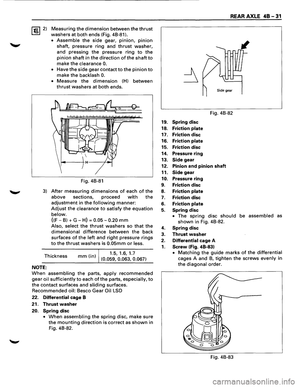
~2) Measuring the dimension between the thrust
washers at both ends (Fig. 48-81 ).
• Assemble the side gear, pinion, pinion
shaft, pressure ring and thrust washer,
and pressing
the pressure ring to the
pinion shaft in the direction of the shaft to
make the clearance 0.
• Have the side gear contact to the pinion to
make the backlash 0.
• Measure the dimension (H) between
thrust washers at both ends.
Fig. 48-81
3) After measuring dimensions of each of the
above sections, proceed with the
adjustment in the following manner:
Adjust the clearance to satisfy the equation
below.
{(F-8) + G-H} = 0.05-0.20 mm
Also, select the thrust washers so that the
dimensional difference between the back
surfaces
of the left and right pressure rings
to the thrust washers is 0.05mm or less.
Thickness (. )
1.5, 1.6, 1.7 mm In (0.059, 0.063, 0.067)
NOTE:
When assembling the parts, apply recommended
gear oil sufficiently to each of the parts, especially, to
the contact surfaces and sliding surfaces.
Recommended oil: 8esco Gear Oil LSD
22. Differential cage B
21. Thrust washer
20. Spring disc
• When assembling the spring disc, make sure
the mounting direction is correct as shown in
Fig. 48-82.
REAR AXLE 48-31
Fig. 48-82
19.
Spring disc
18. Friction plate
17. Friction disc
16. Friction plate
15. Friction disc
14. Pressure ring
13.
Side gear
12. Pinion and pinion shaft
11.
Side gear
10. Pressure ring
9. Friction disc
8. Friction plate
7. Friction disc
6. Friction plate
5. Spring disc
• The spring disc should be assembled as
shown in Fig. 48-82.
4. Spring disc
3. Thrust washer
2. Differential cage A
1. Screw (Fig. 48-83)
• Matching the guide marks of the differential
cages A and 8, tighten the screws evenly in
the diagonal order.
Fig. 48-83
Page 326 of 1928
5A-6 HYDRAULIC BRAKES
NOTE:
Do not allow the fluid level in the reservoir to go below
the half-way mark.
12. Reconnect the brake pipe
(j) to the master
cylinder and tighten the pipe.
13. Depress the brake pedal
slowly once and hold it
depressed.
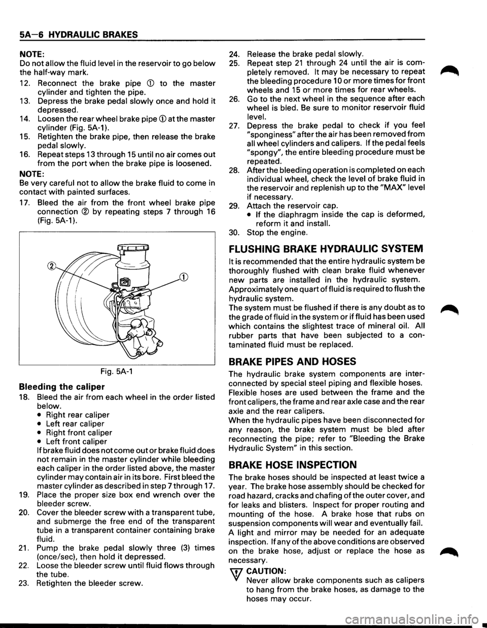
14. Loosen the rear wheel brake pipe (j) at the master
cylinder (Fig. 5A-1).
15. Retighten the brake pipe, then release the brake
pedal
slowly.
16. Repeat steps 13 through 15 until no air comes out
from the port when the brake pipe is loosened.
NOTE:
Be very careful not to allow the brake fluid to come in
contact
with painted surfaces.
17. Bleed the air from the front wheel brake pipe
connection
® by repeating steps 7 through 16
(Fig.
5A-1 ).
Fig. 5A-1
Bleeding the caliper
18. Bleed the air from each wheel in the order listed
below.
• Right rear caliper
• Left rear caliper
• Right front caliper
• Left front caliper
If brake fluid does not come out or brake fluid does
not remain in the master cylinder while bleeding
each
caliper in the order listed above, the master
cylinder may contain air in its bore. First bleed the
master cylinder
as described in step 7 through 17.
19.
Place the proper size box end wrench over the
bleeder screw.
20. Cover the bleeder screw with a transparent tube,
and submerge the free end
of the transparent
tube in a transparent container containing brake
fluid.
21. Pump the brake pedal slowly three (3) times
(once/sec), then
hold it depressed.
22. Loose the bleeder screw until fluid flows through
the tube.
23. Retighten the bleeder screw.
24. Release the brake pedal slowly.
25. Repeat step 21 through 24 until the air is com
pletely removed.
It may be necessary to repeat
the bleeding procedure
10 or more times for front
wheels and 15 or more times for rear wheels.
26. Go to the next wheel in the sequence after each
wheel is bled.
Be sure to monitor reservoir fluid
level.
27. Depress the brake pedal to check if you feel
"sponginess" after the air has been removed from
all wheel cylinders and calipers. If the pedal feels
"spongy", the entire bleeding procedure must be
repeated.
28. After the bleeding operation is completed on each
individual wheel, check the level
of brake fluid in
the reservoir and replenish up to the
"MAX" level
if necessary.
29. Attach the reservoir cap.
• If the diaphragm inside the cap is deformed,
reform
it and install.
30. Stop the engine.
FLUSHING BRAKE HYDRAULIC SYSTEM
It is recommended that the entire hydraulic system be
thoroughly flushed with clean brake fluid whenever
new parts are
installed in the hydraulic system.
Approximately one quart
of fluid is required to flush the
hydraulic system.
The system
must be flushed if there is any doubt as to
the grade
of fluid in the system or iffluid has been used
which contains the
slightest trace of mineral oil. All
rubber parts that have been subjected to a con
taminated fluid
must be replaced.
BRAKE PIPES AND HOSES
The hydraulic brake system components are inter
connected
by special steel piping and flexible hoses.
Flexible hoses are used between the frame and the
front calipers, the frame and rear axle case and the rear
axle and the rear calipers.
When the hydraulic pipes have been disconnected
for
any reason, the brake system must be bled after
reconnecting the pipe; refer to
"Bleeding the Brake
Hydraulic
System" in this section.
BRAKE HOSE INSPECTION
The brake hoses should be inspected at least twice a
year. The brake hose assembly should
be checked for
road hazard, cracks and chafing ofthe outer cover, and
for leaks and blisters. Inspect for proper routing and
mounting
of the hose. A brake hose that rubs on
suspension components
will wear and eventually fail.
A light and mirror may be needed for an adequate
inspection.
If any of the above conditions are observed
on the brake hose, adjust
or replace the hose as
necessary.
\fl CAUTION:
'V Never allow brake components such as calipers
to hang from the brake hoses, as damage to the
hoses may occur.
Page 511 of 1928
ENGINE DIAGNOSIS 6-13
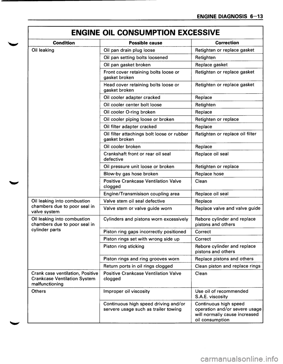
ENGINE OIL CONSUMPTION EXCESSIVE
Condition Possible cause Correction
Oil leaking
Oil pan drain plug loose Retighten or replace gasket
Oil pan setting bolts loosened Retighten
Oil pan gasket broken Replace gasket
Front cover retaining
bolts loose or Retighten or replace gasket
gasket broken
Head cover retaining
bolts loose or Retighten or replace gasket
gasket broken
Oil cooler adapter cracked Replace
Oil cooler
center bolt loose Retighten
Oil cooler 0-ring broken Replace
Oil cooler
piping loose or broken Retighten or replace
Oil filter
adapter cracked Replace
Oil filter
attachings bolt loose or rubber Retighten or replace oil filter
gasket broken
Oil cooler broken Replace
Crankshaft front or rear oil seal Replace oil seal
defective
Oil pressure unit loose or broken Retighten or replace
Blow-by
gas hose broken Replace hose
Positive Crankcase Ventilation
Valve
Clean
clogged
Engine/Transmisison coupling area Replace oil seal
Oil leaking
into combustion Valve stem oil seal defective Replace
chambers due to poor seal in Valve stem or valve guide worn Replace valve and valve guide valve system
Oil leaking into combustion
Cylinders and pistons worn excessively Rebore cylinder and replace
chambers
due to poor seal in pistons and others
cylinder parts
Piston ring gaps incorrectly positioned
Correct
Piston rings set
with wrong side up
Correct
Piston ring sticking Rebore
cylinder and replace
pistons and others
Piston rings and ring grooves
worn Replace pistons and others
Return ports in
oil rings clogged Clean piston
and replace rings
Crank case ventilation, Positive
Positive Crankcase Ventilation
Valve Clean
Crankcase Ventilation System clogged
malfunctioning
Others Improper oil viscosity
Use oil of recommended
S.A.E. viscosity
Continuous high speed driving
and/or Continuous high speed
servere usage such
as trailer towing operation and/or severe usage
will normally cause increased
oil consumption
Page 579 of 1928
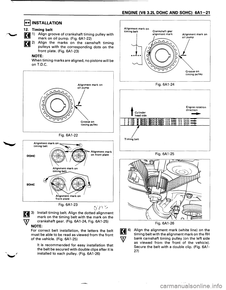
I••IINSTALLATION
12. Timing belt
1£4111) Align groove of crankshaft timing pulley with
mark on oil pump. (Fig. 6A 1-22)
1£4112) Align the marks on the camshaft timing
pulleys with the corresponding dots on the
front plate. (Fig. 6A 1-23)
NOTE:
When timing marks are aligned, no pistons will be
on T.D.C.
,-----------------------------,
Fig. 6A1-22
Groove on timing pulley
Alignment mark on~ ad]
timing belt ·~Alignment mark
DOHC ", ' on front plate Q',
SOHC
Fig. 6A1-23 '"-) ,.· (.)~\,'j
1£4113) Install timing belt. Align the dotted alignment
mark on the timing belt with the mark on the
W crankshaft gear. (Fig. 6A1-24, Fig. 6A1-25)
NOTE:
For correct belt installation, the letters the belt
must be able to be read as viewed from the front
of the vehicle. (Fig. 6A 1-25)
It is recommended for easy installation that
the belt be secured with double clips after it is
installed to each pulley. (Fig. 6A 1-26)
ENGINE (V6 3.2L DOHC AND SOHC) 6A1-21
Alignment mark on timing belt Crankshaft gear alignment mark
L~---
t Cylinder head side
Timing belt
Fig. 6A1-24
Fig. 6A1-25
Fig. 6A1-26
Engine rotation direction
~
Align the alignment mark (white line) on the
timing belt with the alignment mark on the RH
bank camshaft timing pulley (on the left side
as viewed from the front of the vehicle).
Secure
the belt with a double clip. (Fig. 6A 1-
27)
Page 630 of 1928
68 - 2 ENGINE COOLING
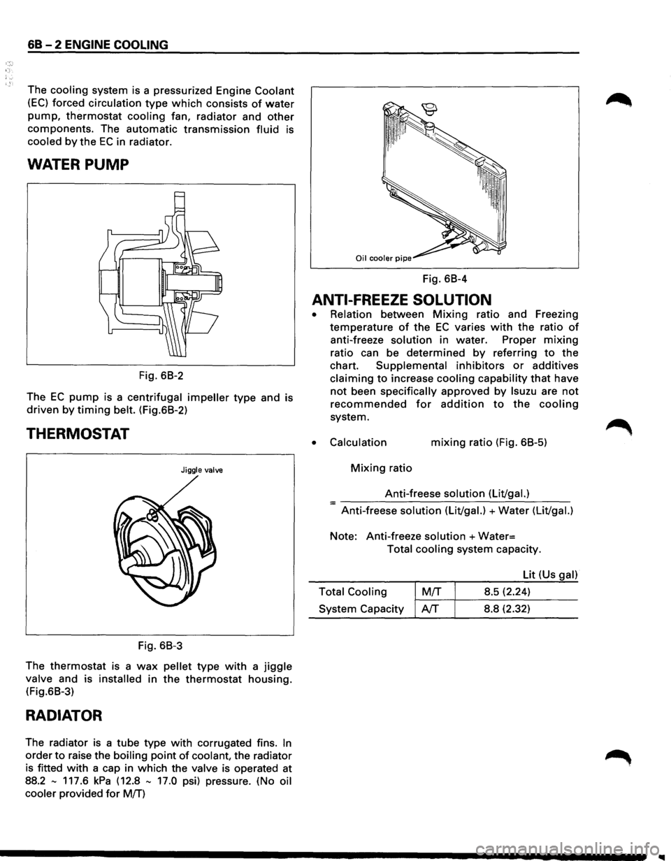
The cooling system is a pressurized Engine Coolant
(EC) forced circulation type which consists of water
pump, thermostat cooling fan, radiator and other
components. The automatic transmission fluid is
cooled by the EC in radiator.
WATER PUMP
Fig. 68-2
The
EC pump is a centrifugal impeller type and is
driven by timing belt. (Fig.68-2)
THERMOSTAT
Jiggle valve
Fig. 68-3
The
thermostat is a wax pellet type with a jiggle
valve and is installed in the thermostat housing.
(Fig.68-3)
RADIATOR
The radiator is a tube type with corrugated fins. In
order to raise the boiling point of coolant, the radiator
is fitted
with a cap in which the valve is operated at
88.2
-117.6 kPa (12.8 - 17.0 psi) pressure. (No oil
cooler
provided for M!f)
Fig. 68-4
ANTI-FREEZE SOLUTION
•
•
Relation between Mixing ratio and Freezing
temperature
of the EC varies with the ratio of
anti-freeze solution in water. Proper mixing
ratio can be determined by referring to the
chart. Supplemental inhibitors or additives
claiming to increase cooling capability that have
not been specifically approved by lsuzu are not
recommended for addition to the cooling
system.
Calculation mixing ratio (Fig. 68-5)
Mixing ratio
Anti-freese
solution (Lit/gal.) =-----------------Anti-freese solution (Lit/gal.) +Water (Lit/gal.)
Note: Anti-freeze solution +Water=
Total cooling system capacity.
Lit (Us
gal)
Total Cooling
M!f 8.5 (2.24) ~-~~--------System Capacity AfT 8.8 (2.32)