glove box ISUZU TROOPER 1995 Workshop Manual
[x] Cancel search | Manufacturer: ISUZU, Model Year: 1995, Model line: TROOPER, Model: ISUZU TROOPER 1995Pages: 1928
Page 53 of 1928
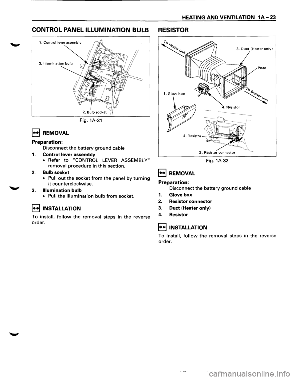
CONTROL PANEL ILLUMINATION BULB
1••1 REMOVAL
Preparation:
Fig. 1A-31
Disconnect
the battery ground cable
1. Control lever assembly
• Refer to "CONTROL LEVER ASSEMBLY"
removal
procedure in this section.
2. Bulb socket
• Pull out the socket from the panel by turning
it counterclockwise.
3.
Illumination bulb
• Pull the illumination bulb from socket.
I••IINSTALLATION
To install, follow the removal steps in the reverse
order.
HEATING AND VENTILATION 1A-23
RESISTOR
1. Glove box
1••1 REMOVAL
Preparation:
3. Duct (Heater only)
Plate
2. Resistor connector
Fig. 1A-32
Disconnect the battery
ground cable
1. Glove box
2. Resistor connector
3. Duct (Heater only)
4. Resistor
I••IINSTALLATION
To install, follow the removal steps in the reverse
order.
Page 82 of 1928
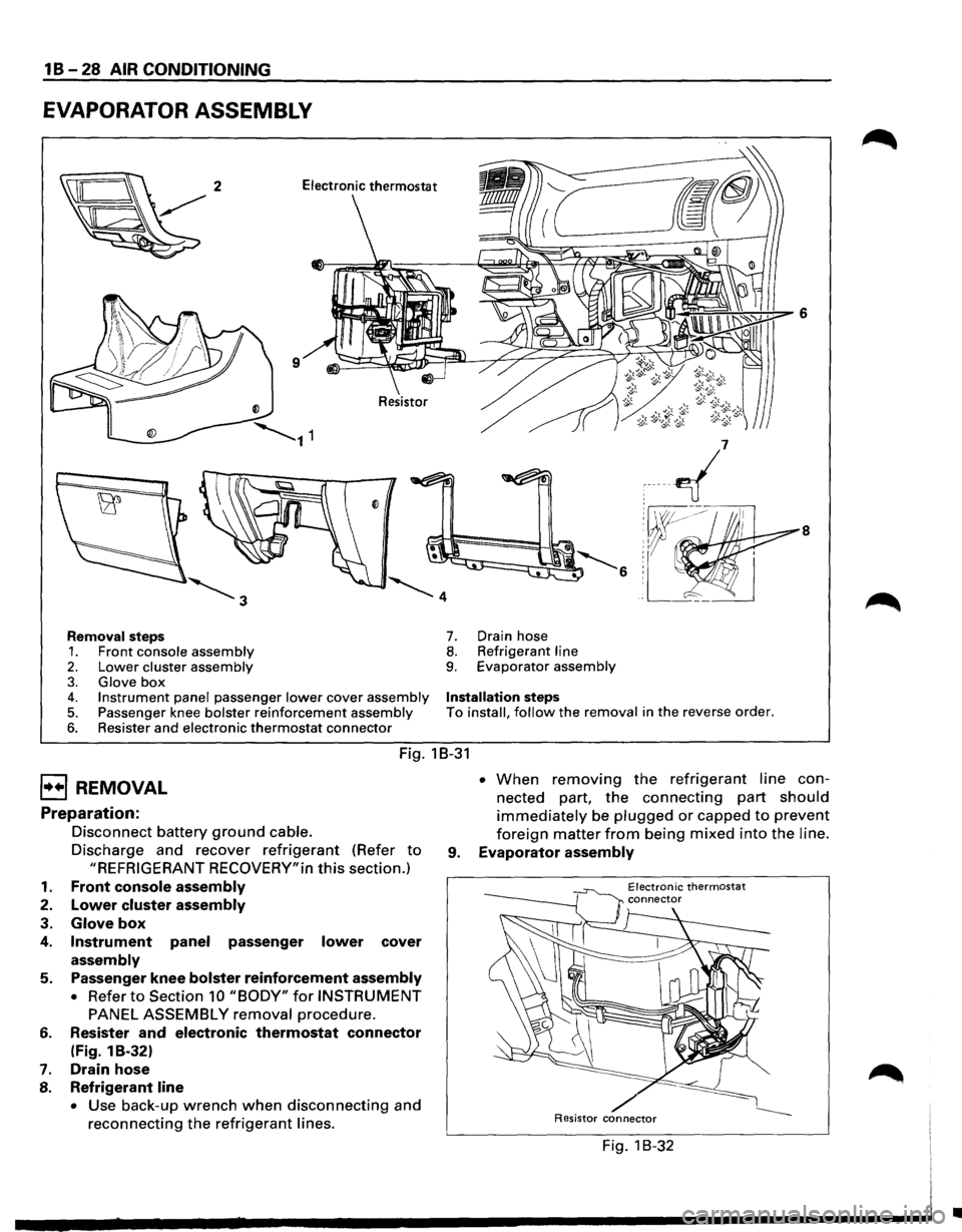
1 B-28 AIR CONDITIONING
EVAPORATOR ASSEMBLY
8
Removal steps 7. Drain hose
1. Front console assembly 8. Refrigerant line
2. Lower cluster assembly 9. Evaporator assembly
3. Glove box 4. Instrument panel passenger lower cover assembly Installation steps
5. Passenger knee bolster reinforcement assembly To install, follow the removal in the reverse order.
6. Resister and electronic thermostat connector
Fig. 18-31
EJ REMOVAL
Preparation:
1.
2.
3.
4.
5.
6.
7.
8.
Disconnect battery ground cable.
Discharge and recover refrigerant (Refer to
"REFRIGERANT RECOVERY"in this section.)
Front console assembly
Lower cluster assembly
Glove box
Instrument panel passenger lower cover
assembly
Passenger knee bolster reinforcement assembly
• Refer to Section 10 "BODY" for INSTRUMENT
PANEL ASSEMBLY removal procedure.
Resister
and electronic thermostat connector
(Fig. 1 B-32)
Drain hose
Refrigerant line
• Use back-up wrench when disconnecting and
reconnecting the refrigerant lines. •
When removing the refrigerant line con
nected part,
the connecting part should
immediately be plugged or capped to prevent
foreign matter from being mixed into the line.
9. Evaporator assembly
Electronic thermostat
/ Resistor connector
Fig. 1 B-32
•
Page 1210 of 1928
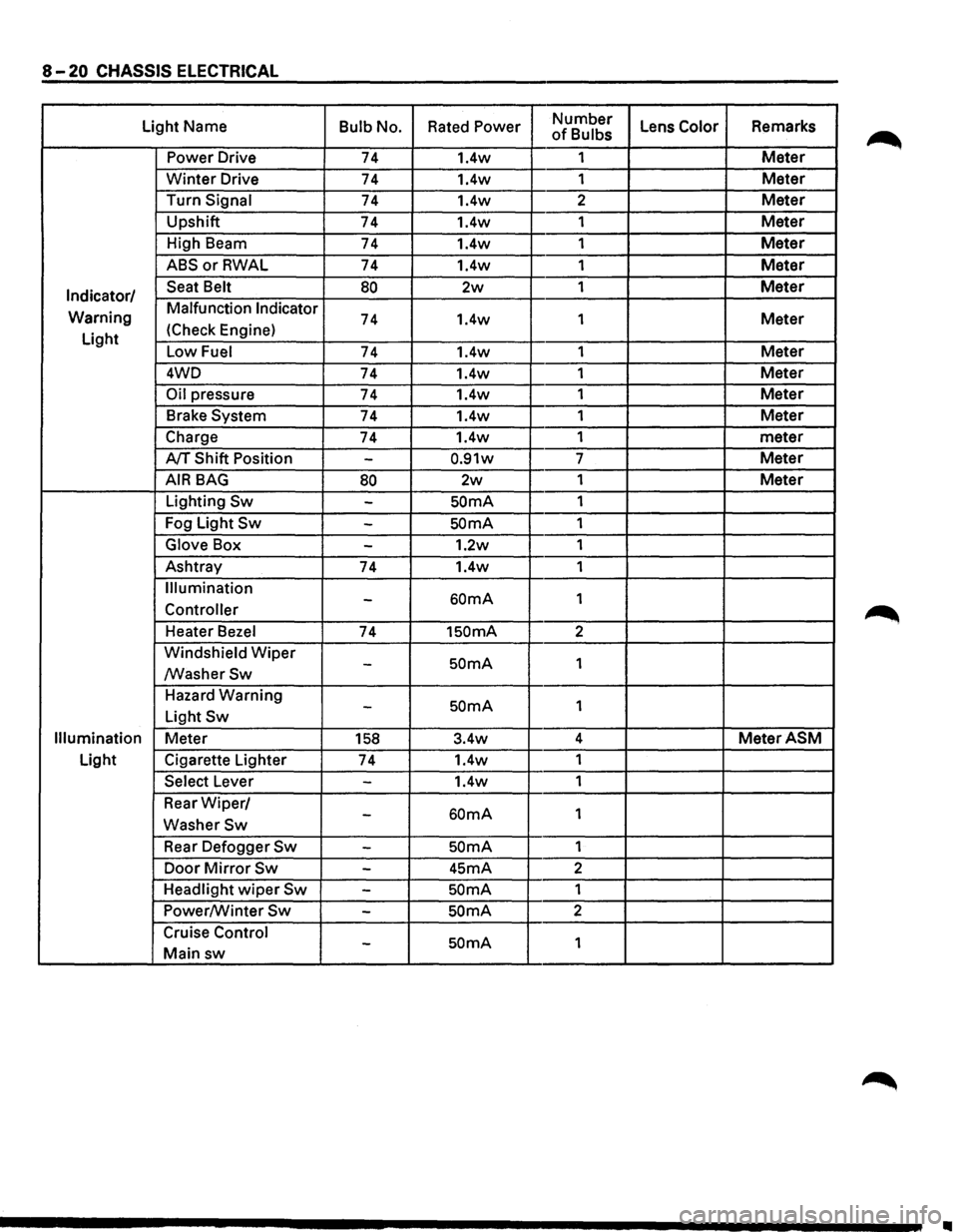
8-20 CHASSIS ELECTRICAL
Light Name Bulb No. Rated Power Number Lens Color Remarks of Bulbs
Power Drive 74 1.4w 1
Meter
Winter Drive 74 1.4w
1 Meter
Turn Signal 74 1.4w 2 Meter
Upshift
74 1.4w 1 Meter
High Beam
74 1.4w 1 Meter
ABSorRWAL 74 1.4w 1 Meter
Indicator/ Seat Belt 80 2w 1 Meter
Warning Malfunction Indicator 74 1.4w
1 Meter
Light (Check
Engine)
Low Fuel 74 1.4w 1 Meter
4WD
74 1.4w 1 Meter
Oil pressure 74 1.4w 1 Meter
Brake System 74 1.4w 1 Meter
Charge 74 1.4w 1
meter
A/T Shift Position -0.91w 7 Meter
AIR BAG 80 2w 1 Meter
Lighting Sw -SOmA 1
Fog Light
Sw -SOmA 1
Glove Box -1.2w 1
Ashtray
74 1.4w 1
Illumination
60mA 1 -Controller
Heater Bezel 74 1SOmA 2
Windshield
Wiper SOmA 1 -/WasherSw
Hazard Warning SOmA 1 -Light Sw
Illumination Meter 158 3.4w 4 MeterASM
Light
Cigarette Lighter
74 1.4w
1
Select Lever -1.4w 1
Rear
Wiper/ 60mA 1 -WasherSw
Rear Defogger Sw -SOmA 1
Door
Mirror Sw -45mA 2
Headlight
wiper Sw -SOmA 1
Power/Winter
Sw -SOmA 2
Cruise Control
SOmA 1 -Main sw
II
Page 1213 of 1928
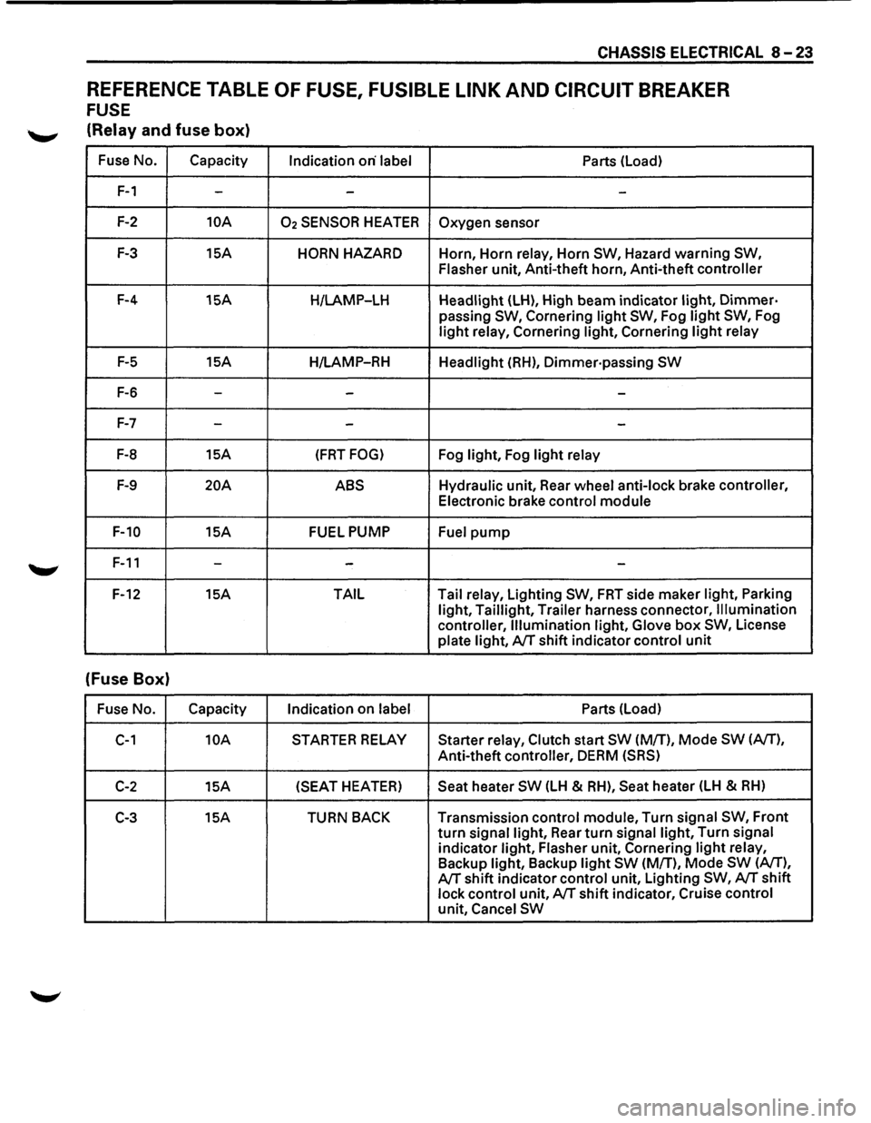
CHASSIS ELECTRICAL 8-23
REFERENCE TABLE OF FUSE, FUSIBLE LINK AND CIRCUIT BREAKER
FUSE
'--"' (Relay and fuse box)
Fuse No. Capacity
Indication on· label Parts (Load)
F-1 --
-
F-2 10A 02 SENSOR HEATER Oxygen sensor
F-3 15A HORN HAZARD Horn, Horn relay, Horn SW, Hazard warning SW,
Flasher
unit, Anti-theft horn, Anti-theft controller
F-4 15A
H/LAMP-LH Headlight (LH), High beam indicator light, Dimmer·
passing SW, Cornering light SW, Fog light SW, Fog
light relay, Cornering light, Cornering light relay
F-5 15A
H/LAMP-RH Headlight (RH), Dimmer·passing SW
F-6 ---
F-7 --
-
F-8 15A (FRT FOG) Fog light, Fog light relay
F-9 20A ABS Hydraulic unit, Rear wheel anti-lock brake controller,
Electronic brake control module
F-10 15A FUEL PUMP
Fuel pump
F-11 ---
F-12 15A TAIL Tail
relay, Lighting SW, FRT side maker light, Parking
light, Taillight, Trailer harness connector, Illumination
controller, Illumination light, Glove
box SW, License
plate light, A/T shift indicator control unit
(Fuse Box)
Fuse No. Capacity
Indication on label Parts (Load)
C-1 10A STARTER RELAY Starter relay, Clutch start SW (M/T), Mode SW (A/T),
Anti-theft controller, DERM (SRS)
C-2 15A (SEAT
HEATER) Seat heater SW (LH & RH), Seat heater (LH & RH)
C-3 15A TURN BACK Transmission control module, Turn signal SW, Front
turn signal light, Rear turn signal light, Turn signal
indicator light, Flasher unit, Cornering light relay,
Backup light, Backup light SW (M/T), Mode SW (A/T),
A/T shift indicator control unit, Lighting SW, A/T shift
lock control unit, A/T shift indicator, Cruise control
unit, Cancel SW
Page 1219 of 1928
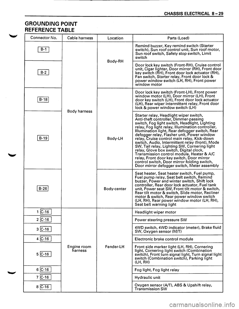
GROUNDING POINT
REFERENCE TABLE
Connector No.
Cable harness
~
~
I B-1a1
Body harness
I B-191
I B-261
1 lc-16 I
2IC-16 I
3IC-16 I
4IC-16 I
Engine room
5IC-16 I
harness
6IC-16 I
7IC-16 I
aiC-16 1
Location
Body-RH
Body-LH
Body-center
Fender-LH
CHASSIS ElECTRICAL 8-29
Parts (Load)
Remind buzzer, Key remind switch (Starter
switch),
Sun roof control unit, Sun roof motor, Sun roof switch, Safety stop switch, Limit
switch
Door lock key switch (Front-RH), Cruise control
unit, Cigar lighter, Door mirror (RH), Front door
key switch (RH), Front door lock actuator (RH),
Fan switch, Starter relay, Front
door lock & power window switch (LH, RH), Front power window motor
Door lock key switch (Front-LH), Front power window motor (LH), Door mirror (LH), Front
door key switch (LH), Front door lock actuator
(LH), Rear wiper intermittent relay, Front door
lock & power window switch (LH)
Starter relay, Headlight
wiper switch,
Anti-theft controller,
Dimmer·passing switch, Fog light switch, Headlight, Lighting
relay, Fog
light relay, Illumination controller,
Illumination light, Rear defogger switch, Rear
defogger relay, Flasher unit,
Power window relay, Cruise control main relay, Kick-down
switch, Audio, Intermittent relay (front), Mode SW, Tail relay, Lighting SW, Cornering light
relay, Glove box switch, Digital clock,
Transmission control module, Heater & A/C
relay, Front
door key switch, Door mirror
control switch, Door mirror folding switch,
Door mirror defogger switch, Meter assembly
Seat heater, Seat heater switch, Fuel pump, Fuel pump relay, Seat belt switch, Remind
buzzer, Power and winter switch, Shift lock
controller, Rear
door lock actuator, Fuel tank
unit, Power seat SW, Front tilt motor & switch,
Rear tilt motor & switch, Slide motor, Recliner
motor & switch, Rear power window switch
(LH, RH), Rear power window motor (LH, RH),
Seat belt warning light
Headlight
wiper motor
Power steering pressure SW
4WD switch, 4WD indicator (meter), Brake fluid
SW, Oxygen sensor (M/T)
Electronic brake control
module
Front side marker light (LH, RH), Cornering
light, Cornering light switch (Combination
switch), Front turn signal light, Turn signal light switch (Combination switch), Parking light (LH, RH)
Fog light, Fog light relay
Hydraulic
unit
Oxygen sensor (AfT), ABS & Upshift relay,
Transmission SW
Page 1266 of 1928
8 -76 CHASSIS ELECTRICAL
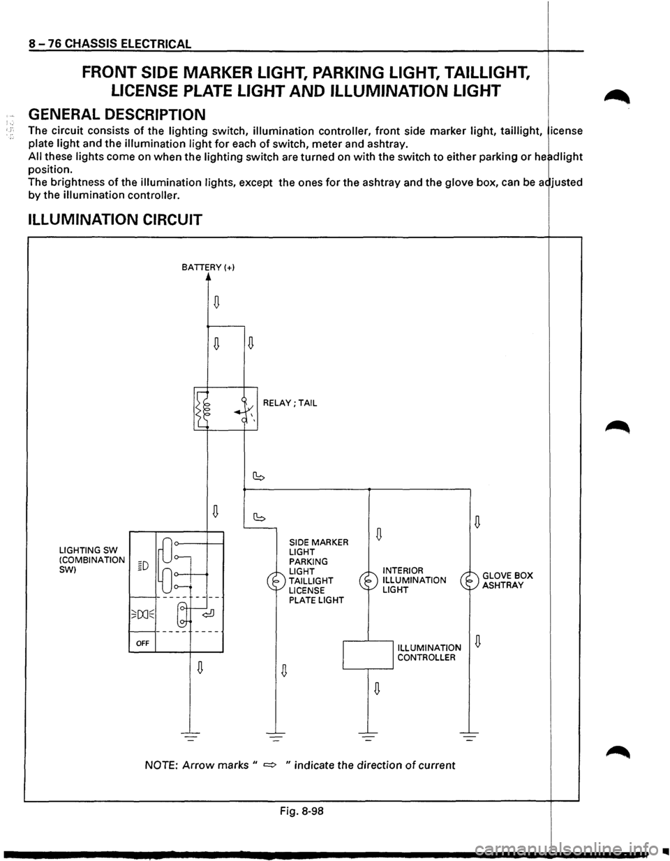
FRONT SIDE MARKER LIGHT, PARKING LIGHT, TAILLIGHT,
LICENSE
PLATE LIGHT AND ILLUMINATION LIGHT
· GENERAL DESCRIPTION ;·. · ;. The circuit consists of the lighting switch, illumination controller, front side marker light, taillight, icense
plate light and the illumination light for each of switch, meter and ashtray.
All these lights come on when the lighting switch are turned on with the switch to either parking or he~dlight
position.
The brightness
of the illumination lights, except the ones for the ashtray and the glove box, can be a< justed
by the
illumination controller.
ILLUMINATION CIRCUIT
LIGHTING SW (COMBINATION
SW)
BATTERY(+)
n n
I~
w ~=o-t--+
f------
;;ooE ~-<0
f-------
OFF
RELAY; TAIL
SIDE
MARKER LIGHT
PARKING
LIGHT
TAILLIGHT
LICENSE
PLATE LIGHT INTERIOR
ILLUMINATION
LIGHT
) )
ILLUMINATION n CONTROLLER c__-,-----'
NOTE: Arrow marks " =:> " indicate the direction of current
Fig. 8-98
GLOVE BOX
ASHTRAY
1111
Page 1267 of 1928
'"T1 (Q cp
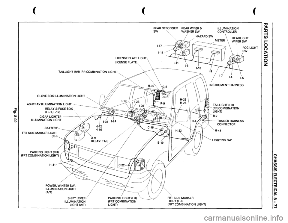
GLOVE BOX ILLUMINATION
LIGHT
ASHTRAY ILLUMINATION
LIGHT
RELAY
& FUSE BOX
(FL-1, F-12)
CIGAR LIGHTER
-----
-~----~
ILLUMINATION
LIGHT
'>
./
BATIERY
FRT
SIDE
MARKER LIGHT
(RH)
PARKING
LIGHT (RHl
(FRT
COMBINATION
LIGHT) H-41
/
I
X-9
....
/
RELAY:T/
I
POWER,
WINTER
SW.
ILLUMINATION LIGHT
I
(NT)
1
PARKING
LIGHT (LH)
(FRT
COMBINATION
LIGHT)
SHIFT
LEVER/
ILLUMINATION
LIGHTINTl
(
REAR
DEFOGGER
REAR
WIPER
&
SW
WASHERSW
ILLUMINATION CONTROLLER
(
HAZARDSW
HEADLIGHT WIPERSW
H-32
",,
FRT
SIDE
MARKER
LIGHT(LH)
(FRT
COMBINATION
LIGHT) TAILLIGHT
(LH)
(RR
COMBINATION
LIGHT)
l"
R-7
FOG
LIGHT
sw
-TRAILER
HARNESS
CONNECTOR
'· 'H-44 LIGHTING
SW
;g ;:Q ~ r-0 0 ~ 0 2
0 :::t )> en en c;; m rm ~ :a 0 )> reo I .... ....
Page 1279 of 1928
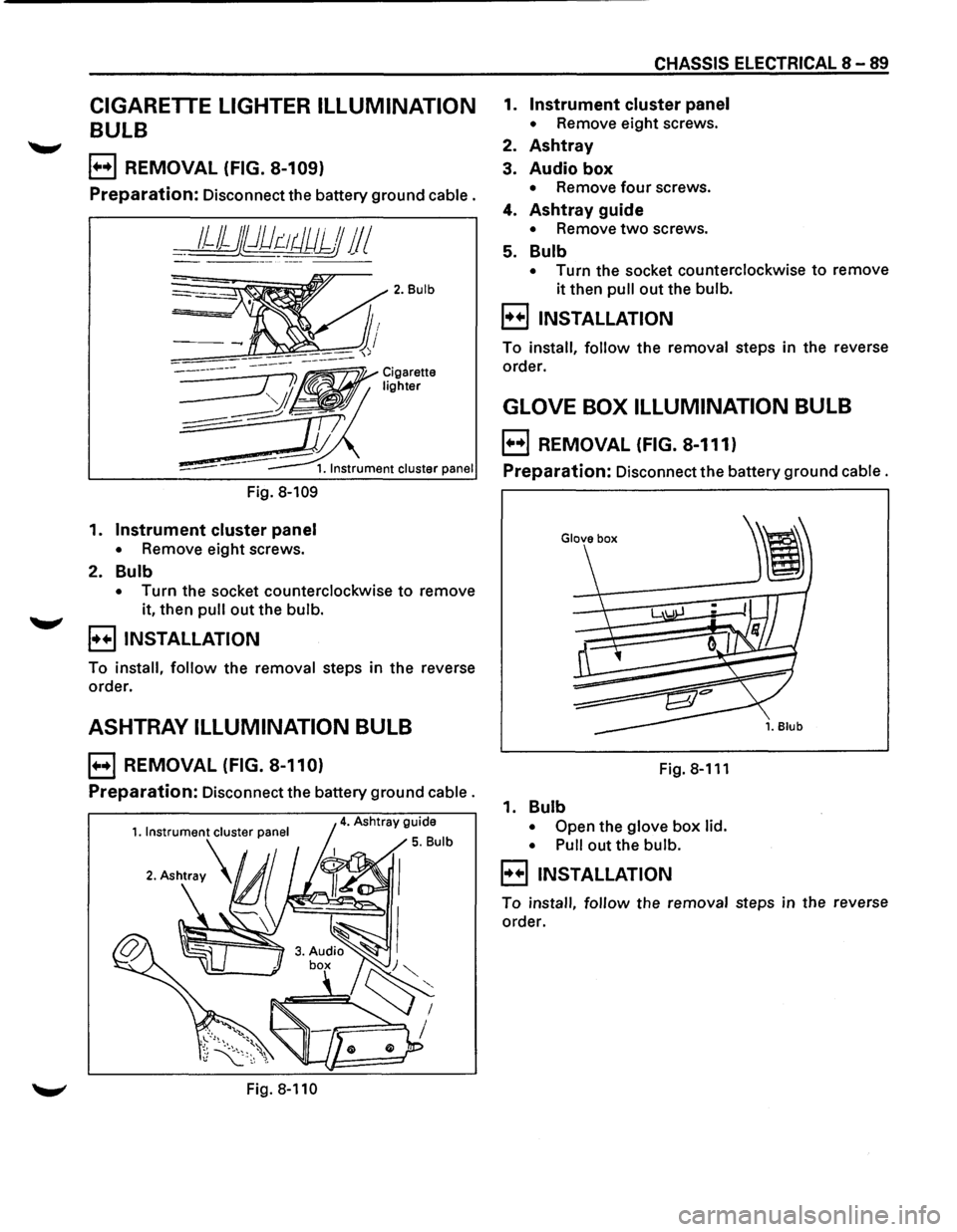
CIGARETTE LIGHTER ILLUMINATION
BULB
E) REMOVAL (FIG. 8-109)
Preparation: Disconnect the battery ground cable.
__ 1JJjj})dr:-~tJUJJJ 11 I
Fig. 8-109
1. Instrument cluster panel
• Remove eight screws.
2. Bulb
2. Bulb
• Turn the socket counterclockwise to remove
it, then
pull out the bulb.
B INSTALLATION
To install, follow the removal steps in the reverse
order.
ASHTRAY ILLUMINATION BULB
E) REMOVAL (FIG. 8-110)
Preparation: Disconnect the battery ground cable.
Fig. 8-110
CHASSIS ELECTRICAL 8-89
1. Instrument cluster panel
• Remove eight screws.
2. Ashtray
3. Audio box
• Remove four screws.
4. Ashtray guide
• Remove two screws.
5. Bulb
• Turn the socket counterclockwise to remove
it then pull out the bulb.
B INSTALLATION
To install, follow the removal steps in the reverse
order.
GLOVE BOX ILLUMINATION BULB
E) REMOVAL (FIG. 8-111)
Preparation: Disconnect the battery ground cable.
Fig.8-111
1. Bulb
• Open the glove box lid.
• Pull
out the bulb.
B INSTALLATION
To install, follow the removal steps in the reverse
order.
Page 1280 of 1928
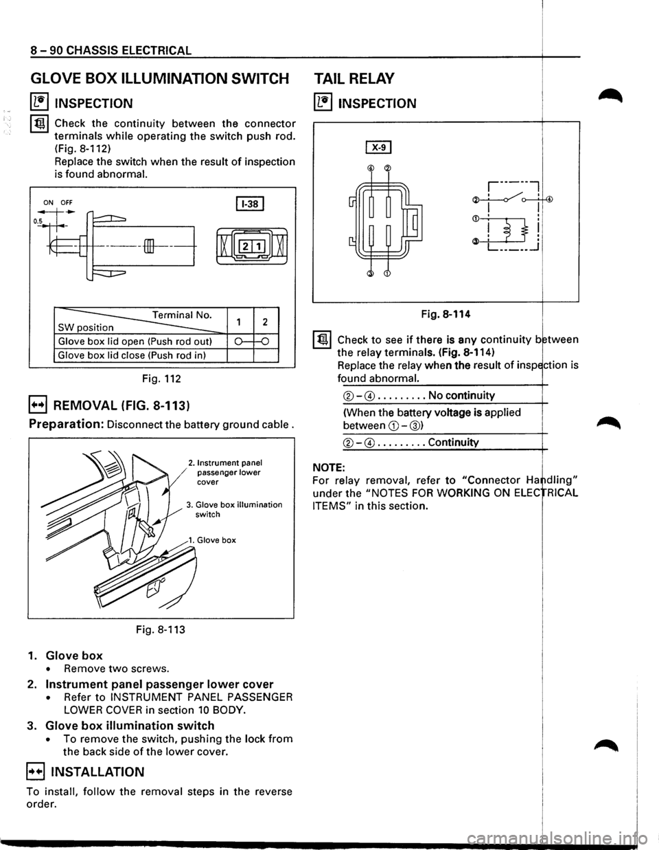
8 -90 CHASSIS ELECTRICAL
GLOVE BOX ILLUMINATION SWITCH
~ INSPECTION
lt!ll Check the continuity between the connector
terminals
while operating the switch push rod.
(Fig.
8-112)
Replace the switch when the result of inspection
is found
abnormal.
ON OFF
SW position
Glove box lid open (Push rod out)
Glove box lid close (Push rod in)
Fig. 112
EJ REMOVAL (FIG. 8-113)
Preparation: Disconnect the battery ground cable.
2. Instrument panel / passenger lower cover
3. Glove box illumination switch
Fig. 8-113
1.
Glove box
• Remove two screws.
2.
Instrument panel passenger lower cover
• Refer to INSTRUMENT PANEL PASSENGER
LOWER COVER in section 10 BODY.
3. Glove box illumination switch
• To remove the switch, pushing the lock from
the back side of the lower cover.
EIINSTALLATION
To install, follow the removal steps in the reverse
order.
TAIL RELAY
~ INSPECTION
Fig. 8-114
I t!ll Check to see if there is any continuity between
the
relay terminals. (Fig. 8-114)
Replace the
relay when the result of inspection is
found abnormal.
®-@ ......... No continuity
(When the battery voltage is
applied
between CD-@) ~
®-@ ......... Continuity
NOTE:
For relay removal, refer to "Connector Ha ~dling"
under the "NOTES FOR WORKING ON ELEC RICAL
ITEMS"
in this section.
Page 1434 of 1928
![ISUZU TROOPER 1995 Workshop Manual 8-244 CHASSIS ELECTRICAL
HEADLIGHT WASHER MOTOR
(b!] INSPECTION
Fig. 8-292
With the washer
motor connector 1 I C-361 connected
to the battery(+) terminal, and the connector 2 IC-361
to the](/img/61/57183/w960_57183-1433.png "ISUZU TROOPER 1995 Workshop Manual 8-244 CHASSIS ELECTRICAL
HEADLIGHT WASHER MOTOR
(b!] INSPECTION
Fig. 8-292
With the washer
motor connector 1 I C-361 connected
to the battery(+) terminal, and the connector 2 IC-361
to the")
8-244 CHASSIS ELECTRICAL
HEADLIGHT WASHER MOTOR
(b!] INSPECTION
Fig. 8-292
With the washer
motor connector 1 I C-361 connected
to the battery(+) terminal, and the connector 2 IC-361
to the battery (-) terminal, check to see if the motor
rotates smoothly. (Fig. 8-292)
Repair
or replace the motor when the result of inspec
tion is found abnormal.
E) REMOVAL AND INSTALLATION
1•+1 Refer to the removal and installation steps ofthe
windshield washer tank/motor under "WIND
SHIELD WIPER/WASHER
AND REAR WIPER/
WASHER"
in this section.
HEADLIGHT WIPER TIMER
B REMOVAL (FIG. 8-293)
Preparation: Disconnect the battery ground cable.
~Hdl"h··· 5. ea 19 t w1per timer
Fig. 8-293
1. Front console assembly
2. Lower cluster assembly
3. Glove box assembly
4. Instrument panel passenger lower cover
• Refer to INSTRUMENT PANEL ASSEMBLY in
Section 10 BODY.
5. Headlight wiper timer
B INSTALLATION
To install, follow the removal steps in the reverse
order.