tire pressure ISUZU TROOPER 1995 Owner's Manual
[x] Cancel search | Manufacturer: ISUZU, Model Year: 1995, Model line: TROOPER, Model: ISUZU TROOPER 1995Pages: 1928
Page 436 of 1928
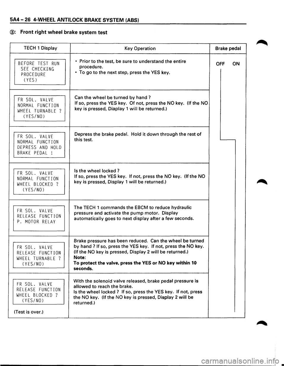
5A4-26 4-WHEEL ANTILOCK BRAKE SYSTEM (ABS)
@: Front right wheel brake system test
TECH 1 Display
Key Operation Brake pedal
BEFORE TEST RUN • Prior to the test, be sure to understand the entire OFF ON
SEE CHECKING procedure.
PROCEDURE • To go to the next step, press the YES key.
(YES)
FR SOL. VALVE Can the wheel be turned by hand ?
NORMAL FUNCTION If so, press the YES key. Of not, press the NO key. (If the NO
WHEEL TURNABLE ? key is pressed, Diaplay 1 will be returned.)
(YES/NO)
FR SOL. VALVE Depress the brake pedal. Hold it down through the rest of
NORMAL FUNCTION this test.
DEPRESS AND HOLD
BRAKE PEDAL !
FR SOL. VALVE Is the wheel locked ?
NORMAL FUNCTION If so, press the YES key. If not, press the NO key. (If the NO
WHEEL BLOCKED ? key is pressed, Display 1 will be returned.)
(YES/NO)
FR SOL. VALVE The TECH 1 commands the EBCM to reduce hydraulic
RELEASE FUNCTION pressure and activate the pump motor. Display
P. MOTOR RELAY automatically goes to next display after a few seconds.
Brake pressure has been reduced.
Can the wheel be turned
FR SOL. VALVE by hand? If so, press the YES key. If not, press the NO key.
RELEASE FUNCTION (If the NO key is pressed, Display 2 will be returned.)
WHEEL TURNABLE ? Note:
(YES/NO) To protect the valve, press the YES or NO key within 10
seconds.
FR SOL. VALVE With the solenoid valve released, brake pedal pressure is
RELEASE FUNCTION allowed to reach the brake.
WHEEL BLOCKED ? Is the wheel locked? If so, press the YES key. If not, press
(YES/NO) the NO key. (If the NO key is pressed, Display 2 will be
returned.)
(Test is over.)
•
Page 438 of 1928
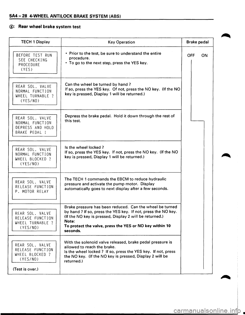
5A4-28 4-WHEEL ANTILOCK BRAKE SYSTEM (ABS)
@: Rear wheel brake system test
TECH 1 Display
Key Operation Brake
pedal
BEFORE TEST RUN • Prior to the test, be sure to understand the entire OFF ON
SEE CHECKING procedure.
PROCEDURE • To go to the next step, press the YES key.
(YES)
REAR SOL. VALVE Can the wheel be turned by hand ?
NORMAL FUNCTION If so, press the YES key. Of not, press the NO key. (If the NO
WHEEL TURNABLE ? key is pressed, Diaplay 1 will be returned.)
(YES/NO)
REAR SOL. VALVE Depress the brake pedal. Hold it down through the rest of
NORMAL FUNCTION this test.
DEPRESS AND HOLD
BRAKE PEDAL !
REAR SOL. VALVE Is the wheel locked ?
NORMAL FUNCTION If so, press the YES key. If not, press the NO key. Of the NO
WHEEL BLOCKED ? key is pressed, Display 1 will be returned.)
(YES/NO)
REAR SOL. VALVE The TECH 1 commands the EBCM to reduce hydraulic
RELEASE FUNCTION pressure and activate the pump motor. Display
P. MOTOR RELAY automatically goes to next display after a few seconds.
Brake pressure has been reduced. Can
the wheel be turned
REAR SOL. VALVE by hand ? If so, press the YES key. If not, press the NO key.
RELEASE FUNCTION (If the NO key is pressed, Display 2 will be returned.)
WHEEL TURNABLE ? Note:
(YES/NO) To protect the valve, press the YES or NO key within 10
seconds.
REAR SOL. VALVE With the solenoid valve released, brake pedal pressure is
RELEASE FUNCTION allowed to reach the brake.
WHEEL BLOCKED ? Is the wheel locked ? If so, press the YES key. If not, press
(YES/NO) the NO key. (If the NO key is pressed, Display 2 will be
returned.)
(Test is over.)
•
Page 507 of 1928
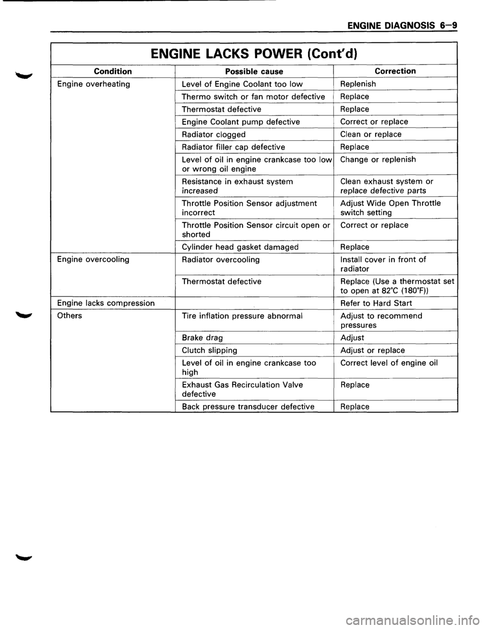
ENGINE DIAGNOSIS 6-9
ENGINE LACKS POWER (Cont'd)
Condition Possible cause Correction
Engine overheating
Level of Engine Coolant too low Replenish
Thermo switch or fan motor defective Replace
Thermostat defective Replace
Engine
Coolant pump defective Correct or replace
Radiator clogged
Clean or replace
Radiator
filler cap defective Replace
Level
of oil in engine crankcase too low Change or replenish
or
wrong oil engine
Resistance in exhaust system
Clean exhaust system or
increased replace
defective parts
Throttle Position Sensor adjustment Adjust
Wide Open Throttle
incorrect switch setting
Throttle Position Sensor circuit open
or Correct or replace
shorted
Cylinder head gasket damaged Replace
Engine overcooling
Radiator
overcooling Install cover
in front of
radiator
Thermostat defective Replace
(Use a thermostat set
to open at a2·c (180.F))
Engine
lacks compression Refer to Hard Start
Others Tire inflation pressure
abnormal Adjust to recommend
pressures
Brake drag Adjust
Clutch slipping Adjust or replace
Level
of oil in engine crankcase too Correct level of engine oil
high
Exhaust Gas
Recirculation Valve Replace
defective
Back pressure transducer defective
Replace
Page 791 of 1928
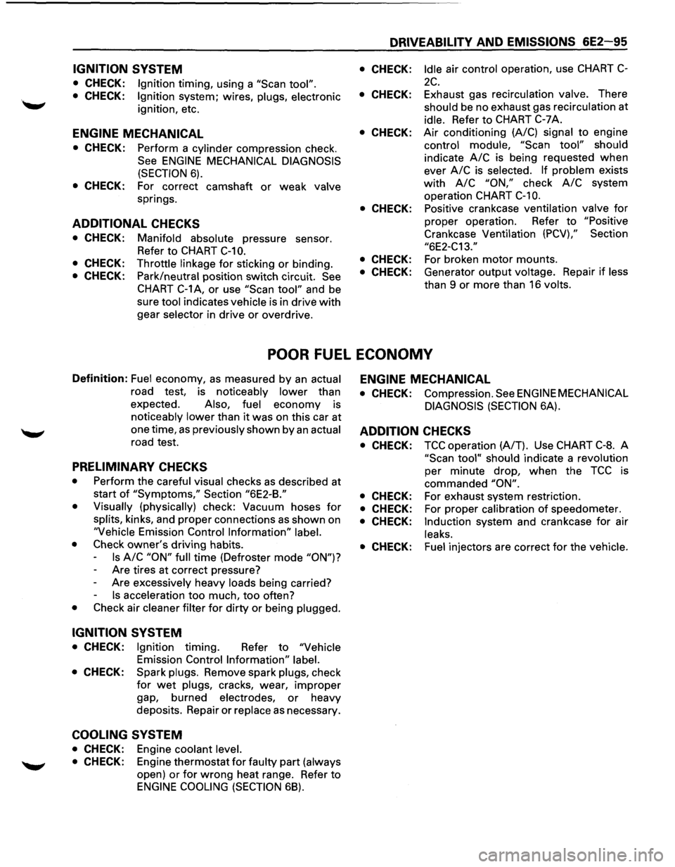
IGNITION SYSTEM
• CHECK: Ignition timing, using a "Scan tool".
• CHECK: Ignition system; wires, plugs, electronic
ignition, etc.
ENGINE MECHANICAL
• CHECK: Perform a cylinder compression check.
See ENGINE MECHANICAL DIAGNOSIS
(SECTION 6).
• CHECK: For correct camshaft or weak valve
springs.
ADDITIONAL CHECKS
• CHECK: Manifold absolute pressure sensor.
Refer to
CHART C-10.
• CHECK: Throttle linkage for sticking or binding.
• CHECK: Park/neutral position switch circuit. See
CHART C-1A,
or use "Scan tool" and be
sure
tool indicates vehicle is in drive with
gear selector in drive or overdrive.
DRIVEABILITY AND EMISSIONS 6E2-95
• CHECK:
• CHECK:
• CHECK:
• CHECK:
• CHECK:
• CHECK:
Idle air control operation, use CHART C-
2C.
Exhaust gas recirculation valve. There
should be no exhaust gas recirculation at
idle. Refer to CHART C-7A.
Air conditioning (A/C) signal to engine
control module, "Scan tool" should
indicate A/C is being requested when
ever
A/C is selected. If problem exists
with A/C "ON," check A/C system
operation
CHART C-10.
Positive crankcase ventilation valve for
proper operation. Refer to "Positive
Crankcase Ventilation (PCV),"
Section
"6E2-C13."
For broken motor mounts.
Generator output
voltage. Repair if less
than 9 or more than 16 volts.
POOR FUEL ECONOMY
Definition: Fuel economy, as measured by an actual
road test, is noticeably lower than
expected.
Also, fuel economy is
noticeably lower than it was on this car at
one time,
as previously shown by an actual
road test.
PRELIMINARY CHECKS
• Perform the careful visual checks as described at
start
of "Symptoms," Section "6E2-B."
• Visually (physically)
check: Vacuum hoses for
splits, kinks, and proper connections as shown on
"Vehicle Emission Control Information" label.
• Check
owner's driving habits.
Is A/C "ON" full time (Defroster mode "ON")?
Are tires at correct pressure?
Are
excessively heavy loads being carried?
Is acceleration too much, too often?
• Check air cleaner filter for dirty or being plugged.
IGNITION SYSTEM
• CHECK: Ignition timing. Refer to "Vehicle
Emission Control Information" label.
• CHECK: Spark plugs. Remove spark plugs, check
for wet plugs, cracks, wear, improper
gap, burned electrodes, or heavy
deposits. Repair or
replace as necessary.
COOLING SYSTEM
• CHECK: Engine coolant level.
• CHECK: Engine thermostat for faulty part (always
open) or for wrong heat range. Refer to
ENGINE COOLING (SECTION 68).
ENGINE MECHANICAL
• CHECK: Compression. See ENGINE MECHANICAL
DIAGNOSIS
(SECTION 6A).
ADDITION CHECKS
• CHECK:
• CHECK:
• CHECK:
• CHECK:
• CHECK:
TCC operation (A/T). Use CHART C-8. A
"Scan tool" should indicate a revolution
per minute drop, when the TCC is
commanded
"ON".
For exhaust system restriction.
For proper
calibration of speedometer.
Induction system and crankcase for air
leaks.
Fuel
injectors are correct for the vehicle.
Page 794 of 1928
6E2-98 DRIVEABILITY AND EMISSIONS
CHART 8-1
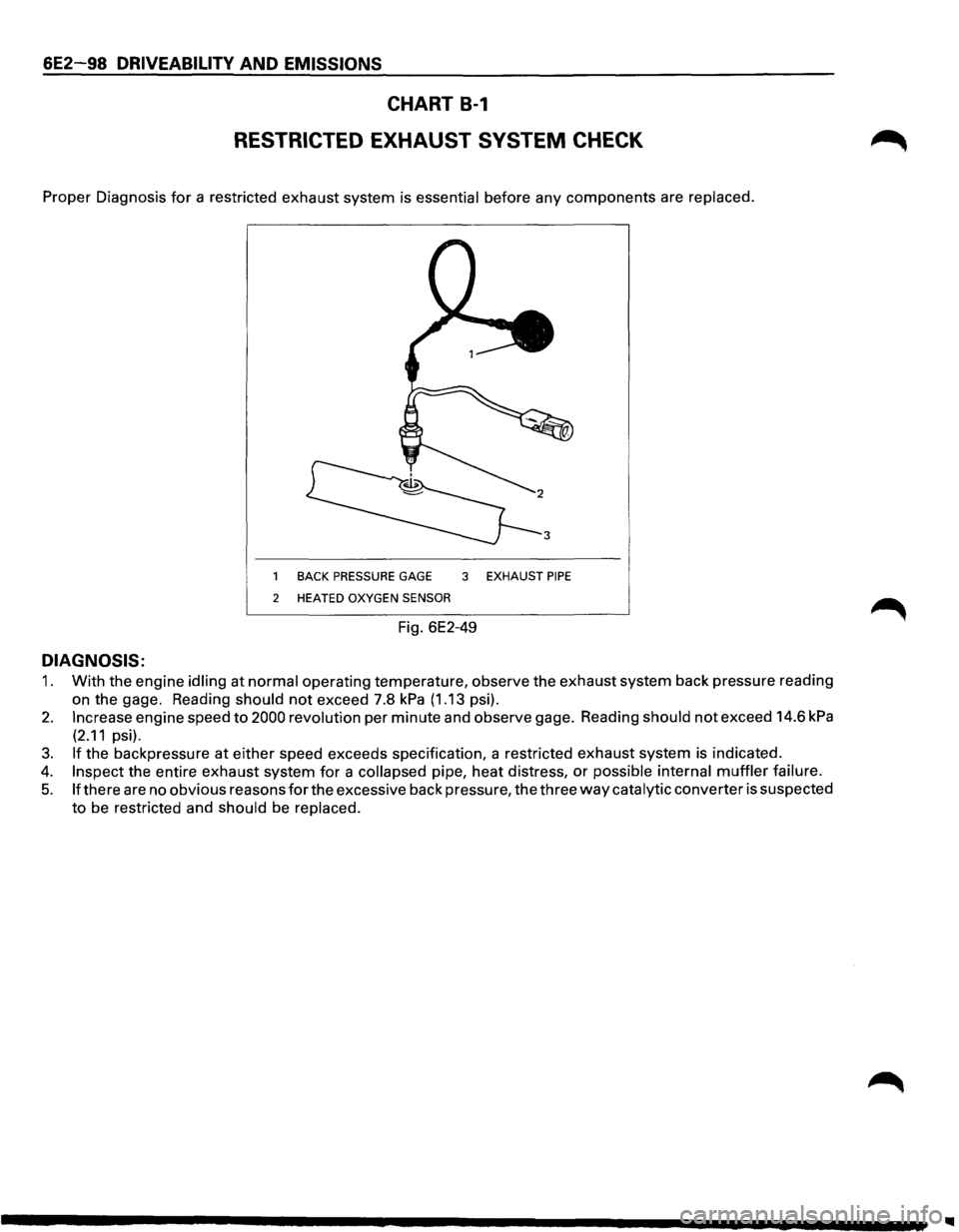
RESTRICTED EXHAUST SYSTEM CHECK
Proper Diagnosis for a restricted exhaust system is essential before any components are replaced.
BACK PRESSURE GAGE 3 EXHAUST PIPE
2 HEATED OXYGEN SENSOR
Fig. 6E2-49
DIAGNOSIS:
1. With the engine idling at normal operating temperature, observe the exhaust system back pressure reading
on the gage. Reading
should not exceed 7.8 kPa (1.13 psi).
2. Increase engine speed to 2000 revolution per minute and observe gage. Reading should not exceed 14.6 kPa
(2.11 psi).
3. If the backpressure at either speed exceeds specification, a restricted exhaust system is indicated.
4. Inspect the entire exhaust system for a collapsed pipe, heat distress, or possible internal muffler failure.
5. If there are no obvious reasons for the excessive back pressure, the three way catalytic converter is suspected
to be restricted and
should be replaced.
Page 803 of 1928
New or service sensors will already have the
compound
applied to the threads. If a sensor is
removed
from an engine and iffor any reason it
is to be reinstalled, the threads must have anti
seize compound
applied before reinstallation.
•
Apply anti-seize compound or equivalent to
threads of oxygen sensor if necessary.
• Tighten the oxygen sensor to the specified
torque.
1~1 Torque N·m (lb·ft) 55 (40)
1. H02S wiring connector
THROTTLE POSITION (TP) SENSOR
Fig. 6E2-59
E) REMOVAL
Preparation: • Battery negative cable.
1. Throttle Position (TP) sensor wiring connector
2. TP sensor fixing screw
3. TP sensor
I••IINSTALLATION
3. TP sensor
2. TP sensor fixing screw
• Tighten the fixing screw to the specified torque.
~~~ Torque N·m (lb·in) I 2 (18)
• Use a "Scan tool" to check TP sensor output
voltage with throttle closed, should be under
0.85 volts. If over 0.85 volts, check for binding
throttle shaft, or TP sensor lever. If all OK,
replace TP sensor.
1.
TP sensor wiring connector
DRIVEABILITY AND EMISSIONS 6E2-1 07
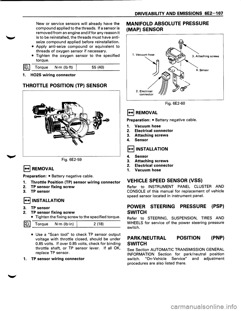
MANIFOLD ABSOLUTE PRESSURE
(MAP) SENSOR
1. Vacuum hose
) 0~
2 .• ,.~,,~,~
conne~ JJJ
4. Sensor
Fig. 6E2-60
E) REMOVAL
Preparation: • Battery negative cable.
1. Vacuum hose
2. Electrical connector
3. Attaching screws
4. Sensor
I••IINSTALLATION
4. Sensor
3. Attaching screws
2. Electrical connector
1. Vacuum hose
VEHICLE SPEED SENSOR (VSS)
Refer to INSTRUMENT PANEL CLUSTER AND
CONSOLE of this manual for replacement of vehicle
speed sensor located in instrument panel.
POWER STEERING PRESSURE (PSP)
SWITCH
Refer to STEERING, SUSPENSION, TIRES AND
WHEELS for service of the power steering pressure
switch.
PARK/NEUTRAL
SWITCH POSITION
(PNP}
See
Section AUTOMATIC TRANSMISSION GENERAL
INFORMATION Section for park/neutral position
switch.
"On-Vehicle Service" and adjustment
procedures are
also listed there.
Page 824 of 1928
6E2-128 DRIVEABILITY AND EMISSIONS
CHART C-2A
INJECTOR BALANCE TEST
The injector balance tester is a tool used to turn the injector on for a precise amount of time, thus spraying a
measured
amount of fuel into the manifold. This causes a drop in fuel rail pressure that we can record and
compare between each injector.
All injectors should have the same amount of pressure drop (± 10 kPa). Any
injector with a pressure drop that is 10 kPa (or more) greater or less than the average drop of the other injectors
should be considered faulty and replaced.
NOTE: It will be necessary to remove the intake plenum to perform this procedure. Refer to intake plenum
remove procedure in this section. It will also be necessary to install the Intake Manifold Diagnostic Plate J
39185 to enable the engine to be run with the plenum removed. Refer to Chart A-8 in Section "6E2-A" of
this service manual.
STEP 1
Engine "cool down" period (10 minutes) is necessary to avoid irregular readings due to "Hot Soak" fuel boiling.
With ignition "OFF" connect fuel gauge J 347301 or equivalent to fuel pressure tap. Wrap a shop towel around
fitting
while connecting gage to avoid fuel spillage. Refer to Chart A-7 in Section 6E2-A, Page 1 of 3.
Disconnect harness connectors at all injectors, and connect injector tester J 34730-3, or equivalent, to one injector.
Follow manufacturers instructions for use of adaptor harness. Ignition must be "OFF" at least 10 seconds to
complete engine control module shutdown cycle. Fuel pump should run about 2 seconds after ignition is turned
"ON". At this point, insert clear tubing attached to vent valve into a operation. Repeat this step until all air is bled
from gauge.
STEP 2
Turn ignition "OFF" for 10 seconds and then "ON" again to get fuel pressure to its maximum. Record this initial
pressure reading. Energize tester one time and note pressure drop at its lowest point (Disregard any slight
pressure increase after drop hits low point). By subtracting this second pressure reading from the initial pressure, ~
we have the actual amount of injector pressure drop.
STEP 3
Repeat step 2 on each injector and compare the amount of drop. Usually, good injectors will have virtually the
same drop. Retest any injector
that has a pressure difference of 10 kPa, either more or less than the average of the
other injectors on the engine.
Replace any injector that also fails the retest. If the pressure drop of all injectors is
within 10 kPa of this average, the injectors appear to be following properly.
Reconnect them and review "Symptoms", Section "6E3-B".
NOTE: The entire test should NOT be repeated more than once without running the engine to prevent flooding.
(This includes any retest on faulty injectors). To run the engine with the intake plenum removed use the
Intake Manifold Diagnostic Plate.
•
Page 825 of 1928
DRIVEABILITY AND EMISSIONS 6E2-129
CHART C-2A
INJECTOR BALANCE TEST
NOTE: The entire test should NOT be repeated more than once without running the engine to prevent flooding.
(This includes any retest on faulty injectors).
The
fuel pressure test in Section "A" Chart A-7, should be completed prior to this test.
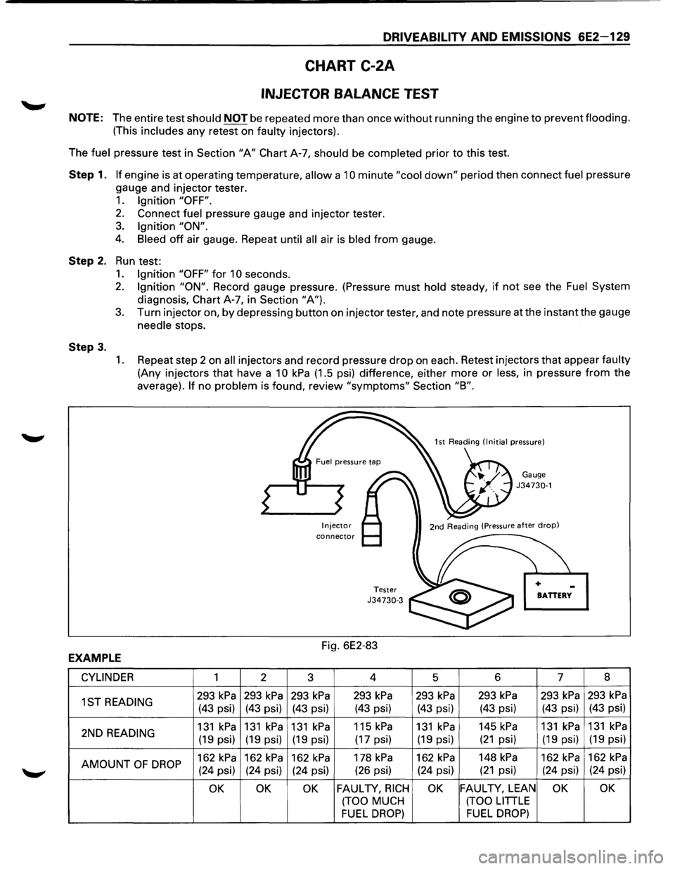
Step 1. If engine is at operating temperature, allow a 10 minute "cool down" period then connect fuel pressure
gauge and injector tester.
1. Ignition "OFF".
2. Connect fuel pressure gauge and injector tester.
3. Ignition "ON".
4. Bleed off air gauge. Repeat until all air is bled from gauge.
Step 2. Run test:
Step 3.
1. Ignition "OFF" for 1 0 seconds.
2. Ignition "ON". Record gauge pressure. (Pressure must hold steady, if not see the Fuel System
diagnosis, Chart A-7, in Section "A").
3. Turn injector on, by depressing button on injector tester, and note pressure at the instant the gauge
needle stops.
1. Repeat step 2 on all injectors and record pressure drop on each. Retest injectors that appear faulty
(Any injectors that have a 10 kPa (1.5 psi) difference, either more or less, in pressure from the
average).
If no problem is found, review "symptoms" Section "8".
Injector connector
Tester J34730-3
Fig. 6E2-83
Gauge J34730-1
BATTERY
EXAMPLE
CYLINDER 1 2
3 4
5 6 7 8
1ST
READING 293 kPa 293 kPa 293 kPa 293 kPa 293 kPa 293 kPa 293 kPa 293 kPa
(43 psi) (43 psi) (43 psi) (43 psi) (43 psi) (43 psi) (43 psi) (43 psi)
2ND
READING 131 kPa 131 kPa 131 kPa 115 kPa 131 kPa 145 kPa 131 kPa 131 kPa
(19 psi) (19 psi) (19 psi) (17 psi) (19 psi) (21 psi) (19 psi) (19
psi)
AMOUNT
OF DROP 162 kPa 162 kPa 162 kPa 178 kPa 162 kPa 148 kPa 162 kPa 162 kPa
(24 psi) (24 psi)
(24 psi) (26
psi) (24 psi) (21 psi) (24 psi) (24 psi)
OK OK OK FAULTY, RICH OK FAULTY, LEAN OK OK
(TOO MUCH (TOO LITTLE
FUEL DROP) FUEL DROP)
Page 1142 of 1928
7C-8 CLUTCH
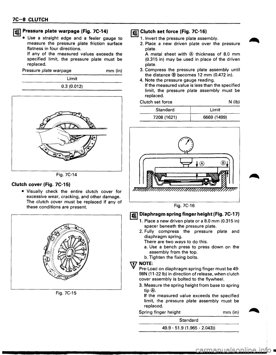
I~U Pressure plate warpage (fig. 7C-14)
• Use a straight edge and a feeler gauge to
measure the pressure plate friction surface
flatness in
four directions.
If any of the measured values exceeds the
specified limit, the pressure plate
must be
replaced.
Pressure plate warpage
Limit
0.3 (0.012)
Fig. 7C-14
Clutch cover (fig. 7C-15)
mm (in)
• Visually check the entire clutch cover for
excessive wear, cracking, and other damage.
The clutch cover
must be replaced if any of
these conditions are present.
Fig. 7C-15
jQI Clutch set force (Fig. 7C-16)
1. Invert the pressure plate assembly.
2. Place a new driven plate over the pressure
plate.
A metal sheet
with @ thickness of 8.0 mm
(0.315 in) may be used in place of the driven
plate
..
3. Compress the pressure plate assembly until
the
distance® becomes 12 mm (0.472 in).
4. Note the pressure gauge reading.
If the measured value is less than the specified
limit, the pressure plate assembly
must be
replaced.
Clutch set force N (lb)
Standard Limit
7:208 (1621) 6669 (1499)
Fig. 7C-16
1•1 Diaphragm spring finger height (fig. 7C-17)
1. Place a new driven plate or a 8.0 mm (0.315 in)
spacer beneath the pressure plate.
2. Fully compress the pressure plate and
diaphragm spring.
There are
two ways to do this.
a. Use a bench press to press down on the
asst~mbly from the top.
b. Tighten the fixing bolts.
IDNOTE:
Yf Pre-Load on diaphragm spring finger must be 49-
98N
(11-~~2 lb) in direction of release, when clutch
cover
assembly is bolted to the flywheel.
3. Measure the spring height from base to spring
tip@.
If the measured value exceeds the specified
limit, the pressure plate assembly
must be
replaced.
Spring finger height
mm (in)
Standard
49.9 -51.9 (1.965 -
2.043))
•
Page 1870 of 1928
10-112 BODY
Fig. 10-231
Fig. 10-232
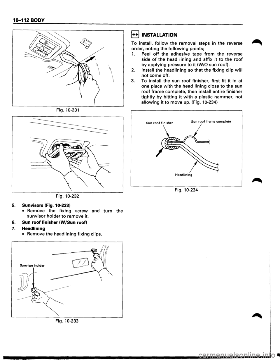
5. Sunvisors (fig. 10·233)
•
Remove the fixing screw and turn the
sunvisor holder to remove it.
6.
Sun roof finisher (W /Sun roof)
7.
Headlining •
Remove the headlining fixing clips.
Sunvisor holder
J
~l I I : 1/
&
Fig. 10-233
I••IINSTALLATION
To install, follow the removal steps in the reverse
order,
noting the following points;
1. Peel off the adhesive tape from the reverse
side
of the head lining and affix it to the roof
by applying pressure to it (W/0 sun roof).
2. Install the headlining so that the fixing clip will
not come off.
3. To install the sun roof finisher, first fit it in at
one
place with the head lining close to the sun
roof frame complete, then install entire finisher
tightly by hitting it with a plastic hammer, not
allowing it to move up. (Fig. 10-234)
Sun roof finisher Sun roof frame complete
Headlining
Fig. 10-234
•