roof ISUZU TROOPER 1995 Workshop Manual
[x] Cancel search | Manufacturer: ISUZU, Model Year: 1995, Model line: TROOPER, Model: ISUZU TROOPER 1995Pages: 1928
Page 57 of 1928
The refrigeration cycle includes the following four
processes as the refrigerant changes repeatedly
from liquid to gas and back to liquid while circulat
ing.
EVAPORATION
The refrigerant is changed from a liquid to a gas in
side
the evaporator. The refrigerant mist that enters
the evaporator vaporizes readily. The liquid refrige
rant removes
the required quantity of heat (latent
heat of vaporization) from the air around the evap
orator core cooling fins and rapidly vaporizes.
Removing the heat cools the air, which is then
radiated
from the fins and lowers the temperature of
the air inside the vehicle.
The refrigerant liquid sent from the expansion valve
and the vaporized refrigerant gas are both present
inside the
evaporator and the liquid is converted to
gas.
With this change from liquid to gas, the pressure
inside
the evaporator must be kept low enough for
vaporization to occur at a lower temperature.
Because of that, the vaporized refrigerant is sucked
into the compressor.
COMPRESSION
The refrigerant is compressed by the compressor
until it is easily liquefied at normal temperature.
The vaporized
refrigerant in the evaporator is sucked
into the compressor. This action maintains the
refrigerant inside the evaporator at a low pressure
so
that it can easily vaporize, even at low tempera
tures close to ooc (32°F).
Also, the refrigerant sucked into the compressor is
compressed inside the
cylinder to increase the
pressure and temperature to values such that the
refrigerant can easily liquefy at normal ambient
temperatures.
CONDENSATION
The refrigerant inside the condenser is cooled by the
outside air and changes from gas to liquid.
The high temperature, high pressure gas coming
from the compressor is cooled and liquefied by the
condenser with outside air and accumulated in the
receiver/drier. The heat radiated to the outside air by
the high temperature, high pressure gas in the
compressor is called heat of condensation. This is
the total quantity of heat (heat of vaporization) the
refrigerant removes
from the vehicle interior via the
evaporator and the work (calculated as the quantity
of heat) performed for compression.
'-' EXPANSION
The expansion valve lowers the pressure of the
refrigerant liquid so that it can easily vaporize.
AIR CONDITIONING 1 B -3
The process of lowering the pressure to encourage
vaporization before the
liquefied refrigerant is sent
to the evaporator is called expansion. In addition,
the expansion valve controls the flow rate of the
refrigerant liquid while decreasing the pressure.
That is, the quantity of refrigerant liquid vaporized
inside
the evaporator is determined by the quantity
of heat which must be removed at a prescribed
vaporization temperature.
It is important that the
quantity of refrigerant be controlled to exactly the
right value.
COMPRESSOR
It compressor performs two main functions:
It compresses low-pressure and low-temperature
refrigerant vapor from the evaporator into high
pressure and high-temperature
refrigerant vapor to
the condenser. And it pumps refrigerant and
refrigerant
oil through the air conditioning system.
This vehicle is equipped with five-vane rotary com
pressor.
The
thermo sensor is installed to the front head of
the compressor to protect it by stopping its
operation when the refrigerant gas is insufficient or
when the temperature is abnormally high.
• OFF ...... 160 ±soc (320.0 ± 9.0°F)
• ON
...... 135 ±soc (27S.O ± 9.0°F)
The specified amount of the compressor oil is 1SOcc
(S.O fl.oz.).
The oil used in the HFC-134a system compressor
differs from that used in R-12 systems.
Also, compressor oil to be used varies according to
the compressor model. Be sure to avoid mixing two
or more different types of oil.
If the wrong oil is used, lubrication will be poor and
the compressor will seize or malfunction.
The magnetic clutch connector is a waterproof
type.
MAGNETIC CLUTCH
The compressor is driven by the drive belt from the
crank
pulley of the engine. If the compressor is ac
tivated each
time the engine is started, this causes
too much load to the engine. The magnetic clutch
transmits the power from the engine to the com
pressor and activates it when the air conditioning is
"ON". Also, it cuts off the power from the engine to
the compressor when the air conditioning is "OFF".
(Magnetic clutch repair procedure can be found in
Section 1 D.)
Page 561 of 1928
CYLINDER BLOCK
The cylinder block is made of aluminum die-cast
casting
for 75° V-type six cylinders. It has a rear plate
integrated structure and employs a deep skirt. The
cylinder liner is cast and the liner inner diameter and
crankshaft
journal diameter are classified into grades.
The crankshaft is supported by four bearings
of which
width is different between No.2, No.3 and No.1, No.4;
the
width of No.3 bearing on the body side is different
in order
to support the thrust bearing. The bearing cap
is made
of nodular cast iron and each bearing cap uses
four bolts and two side bolts.
CYLINDER HEAD
The cylinder head, made of aluminum alloy casting
employs a pent-roof type combustion chamber with a
spark
plug in the center.
The intake and exhaust
valves are placed in V-type
design. The ports are cross-flow type.
VALVE TRAIN
SOHC: The camshafts on both banks are driven by a
timing
belt to operate the valves via rocker arm.
No
further valve clearance adjustment is
required, due
to the Hydraulic lash adjuster
attachedtotherockerarm.
DOHC: Intake camshaft on the both sides of banks are
driven through a
timing belt, while exhaust
camshaft are driven by the both sides
of intake
camshaft through chains.
The driven camshafts open and
close valves
through swing arms.
Valve clearance is automatically adjusted by
means
of HLA built in the cylinder head.
INTAKE MANIFOLD
SOHC: The intake manifold system is composed ofthe
aluminum cast common chamber and intake
manifold attached with six fuel injectors.
DOHC: The intake manifold system is composed of the
aluminum cast common chamber duct having
the induction
control valve, common chamber
and intake
manifold attached with six fuel
injectors.
EXHAUST MANIFOLD
The exhaust manifold is made of nodular cast iron.
PISTONS AND CONNECTING RODS
Aluminum pistons are used after selecting the grade
that meets the cylinder bore diameter. Each piston has
two compression rings and one oil ring. The piston pin
made
of chromium steel is offset 1 mm toward the
thrust side, and the thrust pressure
of piston to the
cylinder wall varies gradually as the piston travels. The
connecting rods are made
of forged steel. The
connecting rod bearings are graded
for correct size
selection.
ENGINE (V6 3.2L DOHC AND SOHC) 6A1-3
CRANKSHAFT AND BEARINGS
The crankshaft is made of Ductile cast-iron.Pins and
journals are graded for correct size selection for their
bearing.
OIL PUMP
The trochoid-type oil pump is driven by crankshaft.
Operation and service procedures are described in this
section.
ENGINE LUBRICATION
The oil discharged by a trochoid-type oil pump driven
by the crankshaft is fed through full-flow oil filter and
engine
coolant cooled oil cooler up to the oil gallery
provided under the crankshaft bearing cap. The oil is
then
led to the crankshaft journals and cylinder head.
The crank pins are
lubricated with oil from crankshaft
journals through oil holes. Also, an oil jet is fed to each
cylinder from crankshaft journals on the connecting
rod
for piston cleaning. The oil pan flange is sealed with
liquid packing only; do not deform or damage the
flange surface during removal or installation.
Page 621 of 1928
·-------------------------------------
ENGINE (V6 3.2L DOHC AND SOHC) 6A1-63
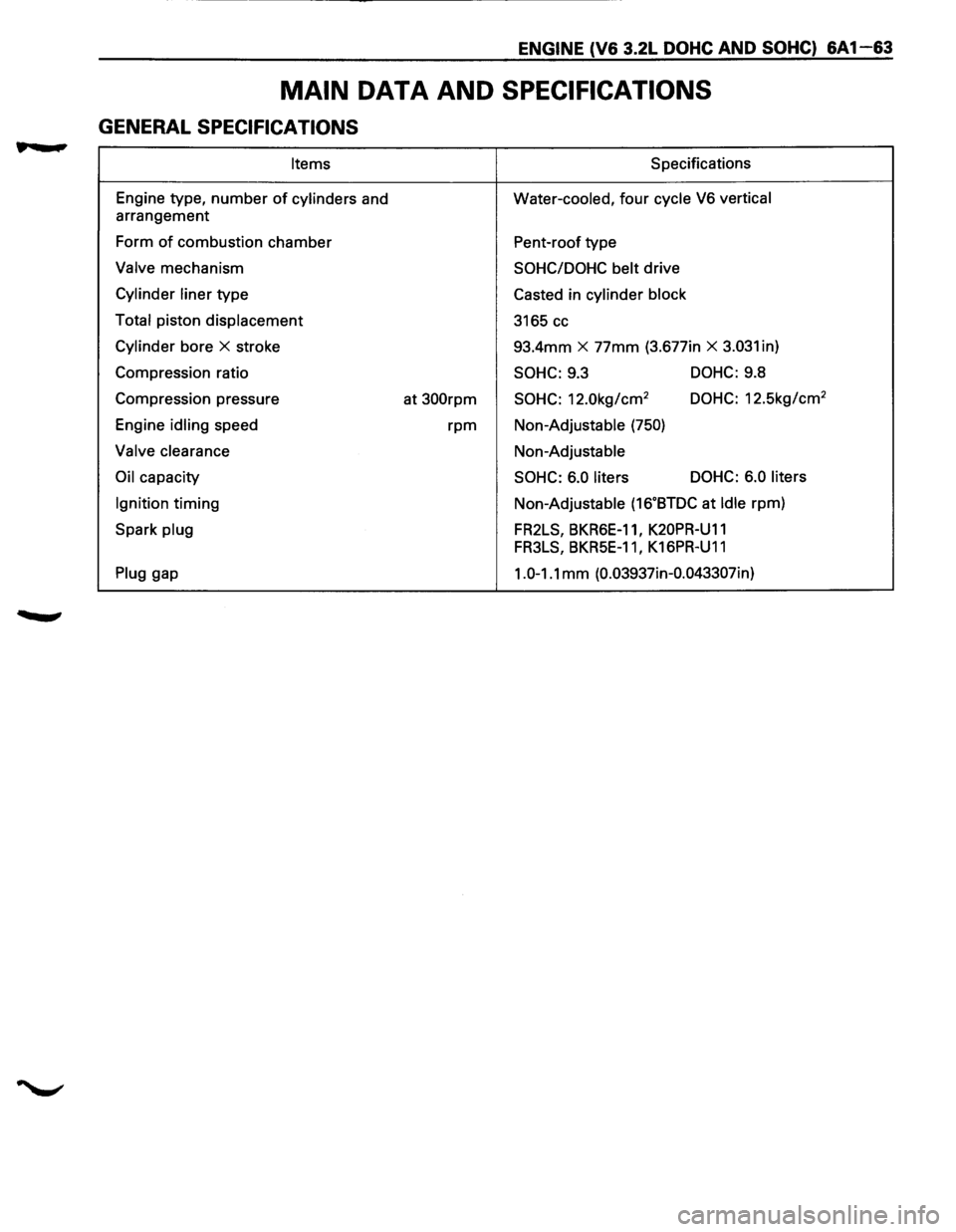
MAIN DATA AND SPECIFICATIONS
GENERAL SPECIFICATIONS
Items S pacifications
Engine type,
number of cylinders and Water-cooled, four cycle V6 vertical
arrangement
Form
of combustion chamber
Pent-roof type
Valve mechanism SOHC/DOHC belt drive
Cylinder liner type
Casted in cylinder block
Total
piston displacement
3165 cc
Cylinder bore X stroke 93.4mm X 77mm (3.677in X 3.031 in)
Compression ratio
SOHC: 9.3 DOHC: 9.8
Compression pressure
at
300rpm SOHC: 12.0kg/cm2 DOHC: 12.5kg/cm2
Engine idling speed rpm Non-Adjustable (750)
Valve clearance Non-Adjustable
Oil capacity SOHC: 6.0 liters DOHC:
6.0 liters
Ignition
timing Non-Adjustable (16.BTDC at Idle rpm)
Spark
plug FR2LS, BKR6E-11, K20PR-U11
FR3LS, BKR5E-11 I K16PR-U11
Plug gap 1.0-1.1 mm (0.03937in-0.043307in)
Page 1191 of 1928

CHASSIS ELECTRICAL 8-1
·SECTION 8
CHASSIS ELECTRICAL
'\f CAUTION: .
When fasteners are removed, always reinstall them at the same location from which they were removed.
If a fastener needs to be replaced, use the correct part number fastener for that application. If the correct
part number fastener is not
available, a fastener of equal size and strength (or stronger) may be used.
Fasteners that are not reused, and those requiring thread
locking compound, will be called out. The correct
torque
values must be used when installing fasteners that require it. If the above conditions are not
followed, parts or system damage could result.
CONTENTS
General Information .................................... 8-2
Notes for Working on Electrical
Items .................................................... 8-2
Symbols and Abbreviations ................. 8-8
Symbols ............................................ 8-8
Abbreviations ................................... 8-9
Parts for Electrical Circuit ..................... 8-10
Wiring ............................................... 8-10
Fuse .................................................. 8-11
Fusible Link ....................................... 8-12
Circuit Breaker ................................... 8-12
Relay ................................................. 8-12
Relay Specifications and
Configurations ................................ 8-13
Diode ................................................. 8-14
Connector ......................................... 8-15
Reading the Circuit Diagram ................ 8-17
Main Data and Specifications .................... 8-19
Bulb Specifications ................................ 8-19
Fuse,
Fusible Link and
Circuit Breaker Location ..................... 8-21
Fuse
Block Circuit .................................. 8-22
Reference Table of Fuse, Fusible
Link and Circuit Breaker ..................... 8-23
Relay Location ....................................... 8-27
Diode Location .......................................
8-28
Grounding Point .................................... 8-29
Reference Table ................................ 8-29
Location ............................................ 8-31
Cable Harness Routing .......................... 8-34
System Repair .............................................. 8-38
Start and Charging ................................ 8-38
Engine Control Module
(ECM) ................................................... 8-47
Headlight and Fog Light ........................ 8-58
Front Side Marker Light, Parking Light,
Taillight, License Plate Light and
Illumination Light .............................. 8-76
Stoplight and Rear Defogger .............. 8-92
Turn Signal Light, Hazard
Warning
Light, Cornering Light,
Backup
Light and Horn ..................... 8-106
Dome Light, Luggage room Light,
Courtesy Light, Map Light,
Seat Belt Switch and
Warning Buzzer ................................. 8-128
Power Door Lock ................................. 8-142
Power
Window .................................... 8-156
Cruise
Control ...................................... 8-172
Anti-Lock Brake
System (ABS) ........... 8-178
Rear
Wheel Anti-Lock Brake
System (RWAL) ................................. 8-185
Transmission
Control Module
(TCM) ................................................. 8-192
A/T Shift Lock ...................................... 8-200
Windshield
Wiper/Washer and
Rear
Wiper/Washer .......................... 8-205
Headlight wiper /washer ..................... 8-232
Audio, Auto Antenna,
Cigarette
Lighter and digital clock ... 8-246
Power Door Mirror ............................... 8-254
Anti-theft System ................................ 8-270
Meter and Warning/Indicator Light ... 8-288
A/T Shift Indicator ............................... 8-336
Heater and
Air Conditioning ............... 8-340
Sun
Roof ............................................... 8-346
Power Seat ........................................... 8-360
Seat
Heater .......................................... 8-37 4
Supplemental Restraint
System (SRS) -AIR BAG ................... 8-382
Page 1194 of 1928
8-4 CHASSIS ELECTRICAL
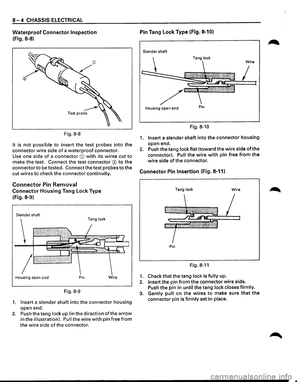
Waterproof Connector Inspection
(Fig. 8-8)
Fig.
8-8
It is not possible to insert the test probes into the
connector wire side
of a waterproof connector.
Use one side
of a connector CD with its wires cut to
make the test. Connect the test connector ® to the
connector
to be tested. Connect the test probes to the
cut wires
to check the connector continuity.
Connector Pin Removal
Connector Housing Tang Lock Type
(Fig. 8-9)
Slender shaft
Tang lock
Housing open pad Pin
Fig. 8-9
Wire
1. Insert a slender shaft into the connector housing
open end.
2. Push the tang lock up (in the direction ofthe arrow
in the illustration). Pull the wire with pin free from
the wire side of the connector.
Pin Tang Lock Type (Fig. 8-10)
Slender shaft
Housing open end
Pin
Fig. 8-10
1. Insert a slender shaft into the connector housing
open
endl.
2. Push the tang lock flat (toward the wire side oft he
connector).
Pull the wire with pin free from the
wire side of the connector.
Connector Pin Insertion (Fig. 8-11)
Tang lock Wire
Pin
Fig. 8-11
1. Check that the tang lock is fully up.
2. Insert the pin from the connector wire side.
Push the pin in
until the tang lock closes firmly.
3. Gently pull on the wires to make sure that the
connector pin is firmly set in place.
Page 1215 of 1928
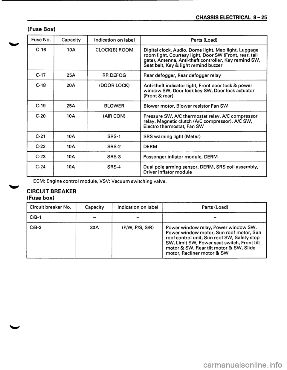
CHASSIS ELECTRICAL 8-25
(fuse Box)
Fuse No.
Capacity Indication on label Parts
(Load)
C-16
10A
CLOCK[B] ROOM Digital clock, Audio, Dome light, Map light, Luggage
room light, Courtesy light, Door SW (Front, rear, tail
gate), Antenna, Anti-theft controller, Key remind SW,
Seat belt, Key & light remind buzzer
C-17 25A RR DEFOG Rear defogger, Rear defogger relay
C-18 20A (DOOR LOCK) Anti-theft indicator light, Front door lock & power
window SW, Door lock key SW, Door lock actuator
(Front
& rear)
C-19 25A BLOWER Blower motor, Blower resistor Fan SW
C-20 10A (AIR CON) Pressure SW, A/C thermostat relay, A/C compressor
relay, Magnetic clutch
(A/C compressor), A/C SW,
Electro thermostat, Fan SW
C-21 10A SRS-1 SRS warning light (Meter)
C-22 10A SRS-2 DERM
C-23
10A SRS-3 Passenger inflator module, DERM
C-24
10A SRS-4 Dual pole arming sensor, DERM, SRS coil assembly,
Driver inflator module
ECM: Engine control module, VSV: Vacuum switching valve.
CIRCUIT BREAKER
(fuse box)
Circuit breaker No.
C/B-1
C/B-2
Capacity
-
30A
Indication on label
-
(P/W, P/S, S/R)
Parts (Load)
-
Power window relay, Power window SW,
Power window motor, Sun roof motor, Sun
roof control unit, Sun roof SW, Safety stop
SW, Limit SW, Power seat switch, Front tilt
motor & SW, Rear tilt motor & SW, Slide
motor, Recliner
motor & SW
Page 1219 of 1928
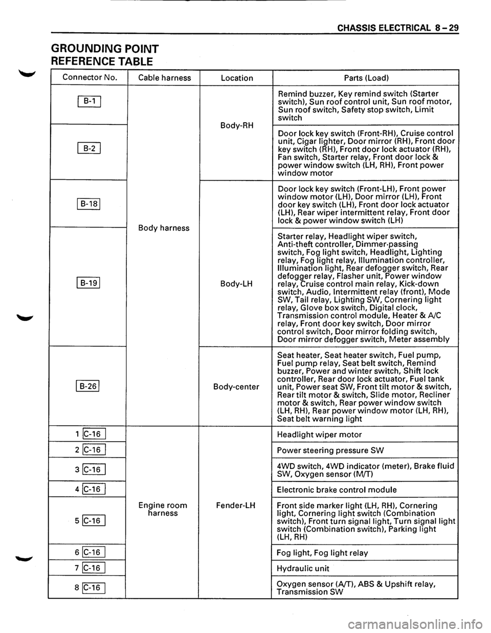
GROUNDING POINT
REFERENCE TABLE
Connector No.
Cable harness
~
~
I B-1a1
Body harness
I B-191
I B-261
1 lc-16 I
2IC-16 I
3IC-16 I
4IC-16 I
Engine room
5IC-16 I
harness
6IC-16 I
7IC-16 I
aiC-16 1
Location
Body-RH
Body-LH
Body-center
Fender-LH
CHASSIS ElECTRICAL 8-29
Parts (Load)
Remind buzzer, Key remind switch (Starter
switch),
Sun roof control unit, Sun roof motor, Sun roof switch, Safety stop switch, Limit
switch
Door lock key switch (Front-RH), Cruise control
unit, Cigar lighter, Door mirror (RH), Front door
key switch (RH), Front door lock actuator (RH),
Fan switch, Starter relay, Front
door lock & power window switch (LH, RH), Front power window motor
Door lock key switch (Front-LH), Front power window motor (LH), Door mirror (LH), Front
door key switch (LH), Front door lock actuator
(LH), Rear wiper intermittent relay, Front door
lock & power window switch (LH)
Starter relay, Headlight
wiper switch,
Anti-theft controller,
Dimmer·passing switch, Fog light switch, Headlight, Lighting
relay, Fog
light relay, Illumination controller,
Illumination light, Rear defogger switch, Rear
defogger relay, Flasher unit,
Power window relay, Cruise control main relay, Kick-down
switch, Audio, Intermittent relay (front), Mode SW, Tail relay, Lighting SW, Cornering light
relay, Glove box switch, Digital clock,
Transmission control module, Heater & A/C
relay, Front
door key switch, Door mirror
control switch, Door mirror folding switch,
Door mirror defogger switch, Meter assembly
Seat heater, Seat heater switch, Fuel pump, Fuel pump relay, Seat belt switch, Remind
buzzer, Power and winter switch, Shift lock
controller, Rear
door lock actuator, Fuel tank
unit, Power seat SW, Front tilt motor & switch,
Rear tilt motor & switch, Slide motor, Recliner
motor & switch, Rear power window switch
(LH, RH), Rear power window motor (LH, RH),
Seat belt warning light
Headlight
wiper motor
Power steering pressure SW
4WD switch, 4WD indicator (meter), Brake fluid
SW, Oxygen sensor (M/T)
Electronic brake control
module
Front side marker light (LH, RH), Cornering
light, Cornering light switch (Combination
switch), Front turn signal light, Turn signal light switch (Combination switch), Parking light (LH, RH)
Fog light, Fog light relay
Hydraulic
unit
Oxygen sensor (AfT), ABS & Upshift relay,
Transmission SW
Page 1326 of 1928
8 -136 CHASSIS ELECTRICAL
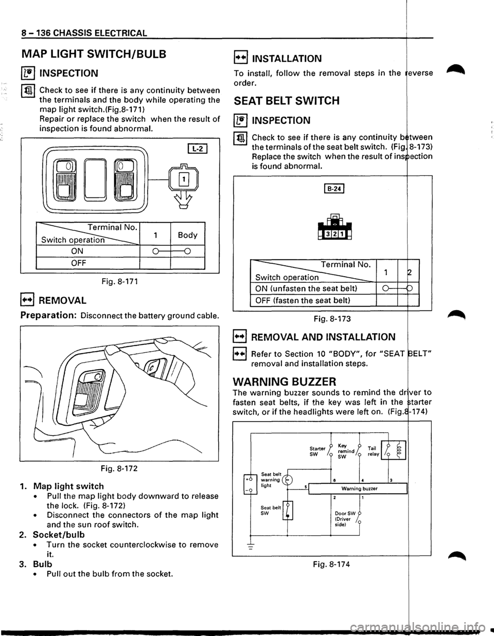
MAP LIGHT SWITCH/BULB
~ INSPECTION
~~~ Check to see if there is any continuity between
the terminals and the body while operating the
map light switch.(Fig.8-171)
Repair
or replace the switch when the result of
inspection is found abnormal.
I" ~ [IT]
ron
0~/~ ~
'
~· 1 Body
n
ON 0 {)
OFF
Fig. 8-171
B REMOVAL
E) INSTALLATION
To install, follow the removal steps in the everse
order.
SEAT BELT SWITCH
~ INSPECTION
I~ l Check to see if there is any continuity b tween
the terminals of the seat belt switch. (Fig 8-173)
Replace the switch when the
result of ins ection
is found abnormal.
Switch operation
ON (unfasten the seat belt)
OFF (fasten the seat belt)
Preparation: Disconnect the battery ground cable. Fig. 8-173
Fig. 8-172
1.
Map light switch
• Pull the map light body downward to release
the
lock. (Fig. 8-172)
• Disconnect the connectors of the map light
and the sun roof switch.
2. Socket/bulb
• Turn the socket counterclockwise to remove
it.
3.
Bulb
• Pull out the bulb from the socket.
B REMOVAL AND INSTALLATION
1++1 Refer to Section 10 "BODY", for "SEAT ELT"
removal and installation steps.
WARNING BUZZER
The warning buzzer sounds to remind the dr ver to
fasten seat belts, if the key was left in the tarter
switch,
or if the headlights were left on. (Fig. -174)
Seat belt warning light
Seat belt
sw
Starter sw
8
Warning buzzer
DoorSW (Driver
side)
Fig. 8-174
..
Page 1536 of 1928
8-346 CHASSIS ELECTRICAL
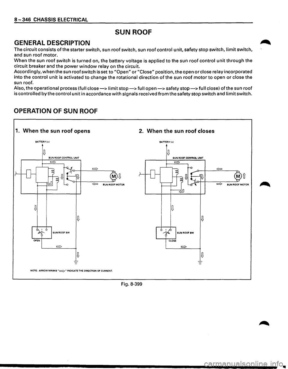
SUN ROOF
GENERAL DESCRIPTION
The circuit consists of the starter switch, sun roof switch, sun roof control unit, safety stop switch, limit switch,
and sun roof motor.
When the sun
roof switch is turned on, the battery voltage is applied to the sun roof control unit through the
circuit breaker and the power
window relay on the circuit.
Accordingly,
when the sun roof switch is set to "Open" or "Close" position, the open or close relay incorporated
into the control
unit is activated to change the rotational direction of the sun roof motor to open or close the
sun roof.
Also, the operational process (full close-> limit stop-> full open-> safety stop-> full close) ofthe sun roof
is
controlled by the control unit in accordance with signals received from the safety stop switch and limit switch.
OPERATION OF SUN ROOF
1. When the sun roof opens 2. When the sun roof closes
BATTERY(+!
BATTERY(+)
D D SUN ROOF CONTROL UNIT SUN ROO!' CONTIIOI. UNIT
D D
D
D
SUNROOF SW SUNROOFSW
D D
NOTE: ARROW MARKS • =:> • INDICATE THE DIRECTlON 01' CURRENT.
Fig. 8-399
Ill
Page 1537 of 1928
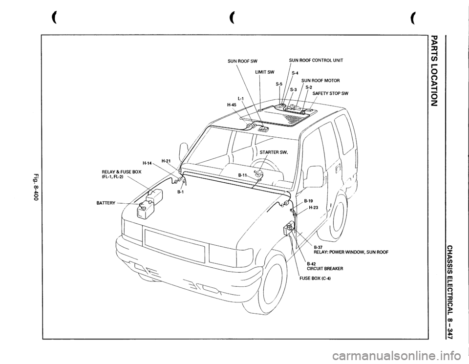
"'TI ce· (X) I "" 0 0
(
RELAY
& FUSE
BOX
IFL-1,
FL-2)
H-14
BATTERY
' -
,¢_
( SUN
ROOFSW
LIMITSW
SUN
ROOF
CONTROL
UNIT
SAFETY
STOP
SW
I " B-37 RELAY:
POWER
WINDOW,
SUN
ROOF
B-42 CIRCUIT
BREAKER
(
~ ::a -1 en r-0 (") ~ 0 2
0 :I: )> CJ) CJ) c;; m rm ~ ::D ~ r-eo I w .,. -..I