tire pressure ISUZU TROOPER 1995 User Guide
[x] Cancel search | Manufacturer: ISUZU, Model Year: 1995, Model line: TROOPER, Model: ISUZU TROOPER 1995Pages: 1928
Page 201 of 1928
WHEELS AND TIRES 3E-1
SECTION 3E
WHEELS AND TIRES
W CAUTION:
When fasteners are removed, always reinstall them at the same location from which they were removed.
If a fastener needs to be replaced, use the correct part number fastener for that application. If the correct
part
number fastener is not available, a fastener of equal size and strength (or stronger) may be used.
Fasteners
that are not reused, and those requiring thread locking compound, will be called out. The correct
torque value must be used when installing fasteners that require it. If the above conditions are not
followed, parts or system damage could result.
CONTENTS
General Description . . . . . . . . . . . . . . . . . . . . . . . . . . . . . . . 3 E -1 Unit Repair .......................................... 3E-7
Diagnosis ........................................... 3E-2 Tires ............................................... 3E-7
Irregular and Premature Wear ................ 3E-2 Wheels ............................................ 3E-7
Inflation of Tires ................................. 3 E- 3 General Balance Procedure ................... 3E-8
Diagnosis List. . . . . . . . . . . . . . . . . . . . . . . . . . . . . . . . . . . . 3 E- 3 Balancing Wheel and Tire ...................... 3E-8
On-Vehicle Service ................................ 3E-6 Main Data and Specifications .................... 3E-9
Wheels ............................................ 3E-6 General Specifications ......................... 3E-9
Torque Specifications .......................... 3E-9
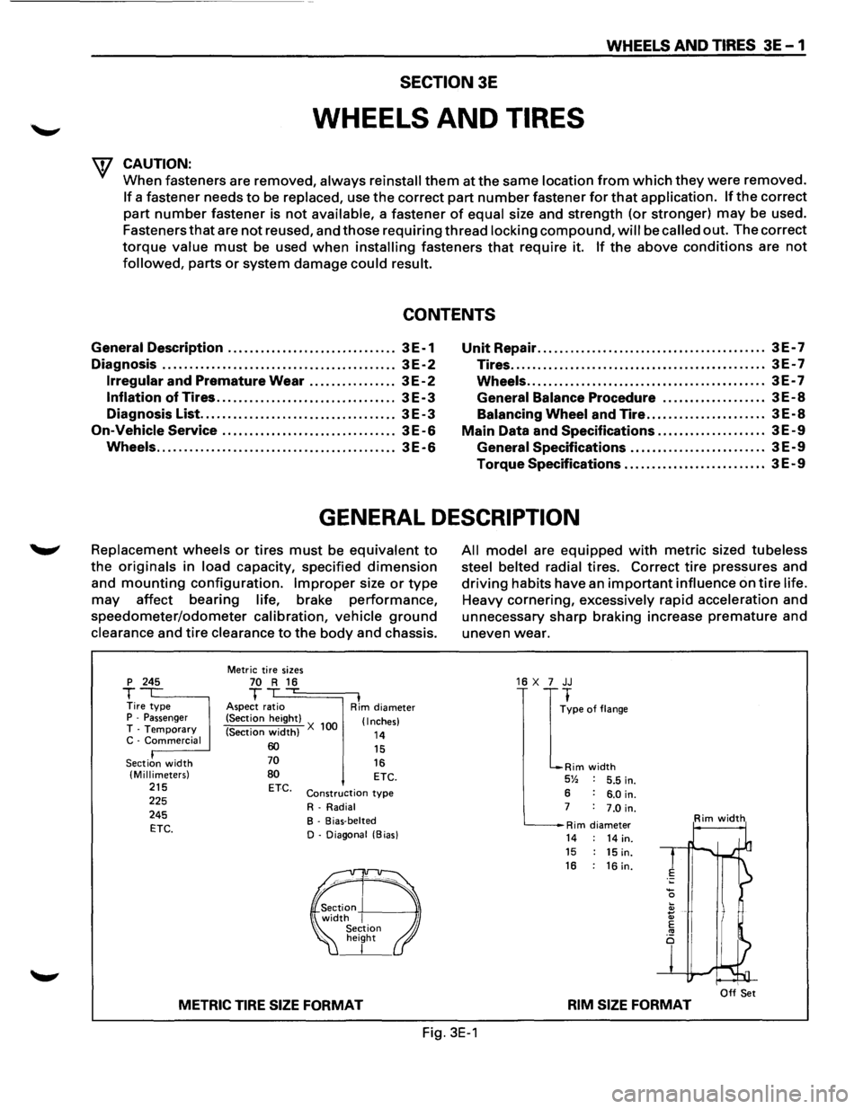
GENERAL DESCRIPTION
Replacement wheels or tires must be equivalent to
the originals in load capacity, specified dimension
and mounting configuration. Improper size or type
may affect bearing life, brake performance,
speedometer/odometer calibration, vehicle ground
clearance and tire clearance to the body and chassis.
p 245
T Tire type P -Passenger T -Temporary C -Commercial
Section
width (Millimeters) 215 225
245
ETC.
Metric tire sizes 70 R 16 T ,...
Aspect ratio I Rim diameter
(Section height)
(Section
width) X 100 (Inches)
14 60 70
80 ETC.
15
16 ETC.
Construction type
R-Radial
B - Bias-belted
D - Diagonal (Bias)
METRIC TIRE SIZE FORMAT
All model are equipped with metric sized tubeless
steel belted radial
tires. Correct tire pressures and
driving habits have an important influence on tire life.
Heavy cornering, excessively rapid acceleration and
unnecessary sharp braking increase
premature and
uneven wear.
16 X 7 JJ
I
~pe of flange
Rim width 5% 5.5 in.
6 6.0 in. 7 7.0 in.
Rim diameter Rim width
14 14 in. 15 15 in. 16 : 16 in.
I Off Set RIM SIZE FORMAT
Fig. 3E-1
Page 202 of 1928
3E-2 WHEELS AND TIRES
DIAGNOSIS
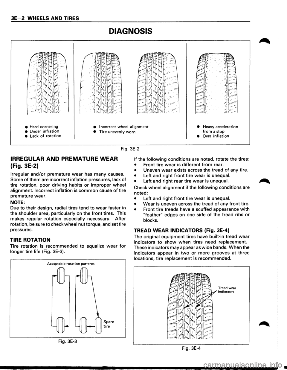
• Hard cornering • Incorrect wheel alignment
• Heavy acceleration from a stop • Under infration • Tire unevenly worn • Lack of rotation • Over inflation
Fig. 3E-2
IRREGULAR AND PREMATURE WEAR
(Fig. 3E-2)
Irregular and/or premature wear has many causes.
Some of them are incorrect inflation pressures, lack of
tire rotation, poor driving habits or improper wheel
alignment. Incorrect inflation
is common cause of tire
premature wear.
NOTE:
Due to their design, radial tires tend to wear faster in
the
shoulder area, particularly on the front tires. This
makes
regular rotation especially necessary. After
rotation, be sure to check wheel nut torque, and set tire
pressures.
TIRE ROTATION
Tire rotation is recommended to equalize wear for
longer tire life (Fig. 3E-3).
Acceptable rotation patterns
Fig. 3E-3
Spare tire
If the following conditions are noted, rotate the tires:
• Front tire wear is different from rear.
• Uneven wear exists across the tread of any tire.
• Left and right front tire wear is unequal.
•
Left and right rear tire wear is unequal.
Check wheel alignment if the following conditions are
noted:
• Left and right front tire wear is unequal.
•
Wear is uneven across the tread of any front tire.
• Front tire treads have a scuffed appearance with
"feather" edges on one side of the tread ribs or
blocks.
TREAD WEAR INDICATORS (fig. 3E-4)
The original equipment tires have built-in tread wear
indicators to show when tires need replacement.
These indicators may appear as wide bands. When the
indicators appear in
two or more grooves at three
locations, tire replacement is recommended.
Fig. 3E-4
Tread wear
indicators
•
Page 203 of 1928
INFLATION OF TIRES
Tire pressure, in cold condition (after vehicle has setfor
three hours or more, and driven less than one mile),
should
be checked monthly or before any extended
trip. Tire pressure increases
approximately 15% when
the tires become hot during driving. Tire pressure
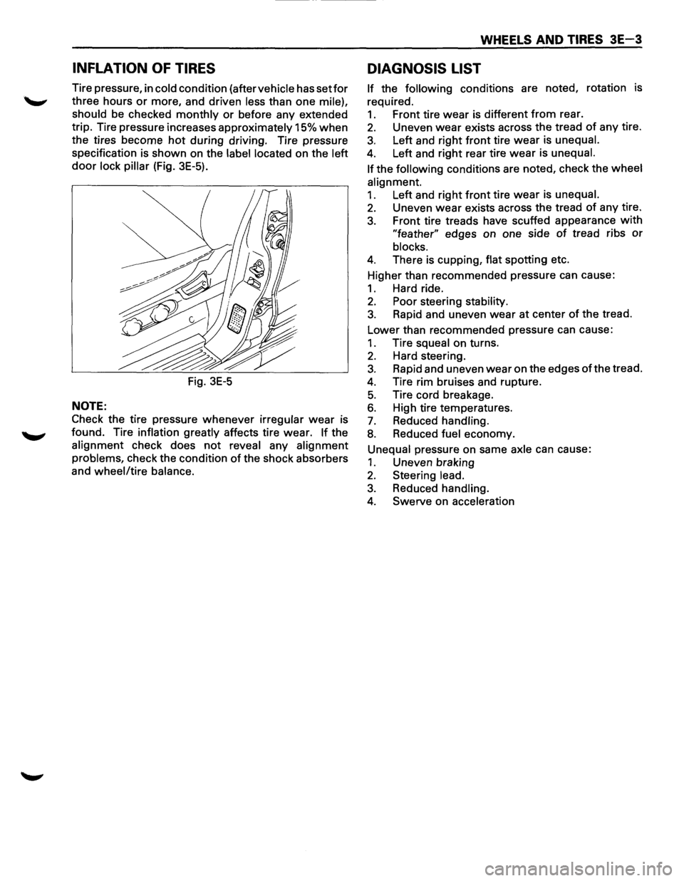
specification is shown on the
label located on the left
door lock pillar (Fig. 3E-5).
Fig.
3E-5
NOTE:
Check the tire pressure whenever irregular wear is
found. Tire
inflation greatly affects tire wear. If the
alignment check does not reveal any alignment
problems,
check the condition of the shock absorbers
and
wheel/tire balance.
WHEELS AND TIRES 3E-3
DIAGNOSIS LIST
If the following conditions are noted, rotation is
required.
1. Front tire wear is different from rear.
2. Uneven wear exists across the tread of any tire.
3. Left and right front tire wear is unequal.
4. Left and right rear tire wear is unequal.
If
the following conditions are noted, check the wheel
alignment.
1. Left and right front tire wear is unequal.
2. Uneven wear exists across the tread of any tire.
3. Front tire treads have scuffed appearance with
"feather" edges on one side of tread ribs or
blocks.
4. There is cupping, flat spotting etc.
Higher than recommended pressure can cause:
1. Hard ride.
2. Poor steering stability.
3. Rapid and uneven wear at center of the tread.
Lower than recommended pressure can cause:
1. Tire squeal on turns.
2. Hard steering.
3. Rapid and uneven wear on the edges of the tread.
4. Tire rim bruises and rupture.
5. Tire cord breakage.
6. High tire temperatures.
7. Reduced handling.
8. Reduced fuel economy.
Unequal pressure on same axle can cause:
1. Uneven braking
2. Steering lead.
3. Reduced handling.
4. Swerve on acceleration
Page 207 of 1928
WHEELS AND TIRES 3E-1
TIRES
REPLACEMENT
UNIT REPAIR
WHEELS
REPLACEMENT
When replacement is necessary, the original metric
the size should be used. Most metric tire sizes do not
have exact corresponding alphanumeric tire sizes. It
is recommended that new tires be installed in pairs on
the same axle. If necessary to replace only one tire, it
should be paired with tire having the most tread, to
equalize braking traction.
w CAUTION:
Do not mix different types of tires such as radial,
bias and bias-belted tires except in emergencies,
because
vehicle handling may be seriously
affected and may result in loss of control.
TIRE DISMOUNTING
Remove valve cap on valve step and deflate the tire.
Then use a
tire changing machine to mount or
dismount tires.
Follow the equipment manufacturer's instruction. Do
not use hand tools or tire lever alone to change tires
as they may damage the tire beads or wheel rim.
TIRE MOUNTING
Rim bead seats should be cleaned with a wire brush
....._., or coarse steel wool to remove lubricants, and light
rust. Before mounting a tire, the bead area should be
well lubricated with an approved tire lubricant.
After mounting, inflate the tire to 196kPa (28 psi) so
that beads are completely seated. Inflate the air to
specified pressure and install valve cap to the stem.
\f WARNING:
Never stand over tire when inflating. Bead may
break when bead snaps over rim's safety hump
and cause serious personal injury.
Never exceed
240 kPa (35 psi) pressure when
inflating. If 240 kPa (35 psi) pressure will not
seat beads, deflate, re-lubricate and re-inflate.
Over
inflation may cause the bead to break and
cause serious
personal injury.
TIRE REPAIR
There are many different materials on the market
used to repair tires.
Manufacturers have published detailed instructions
on how and when to repair tires. These instructions
can be obtained from the tire manufacturer if they are
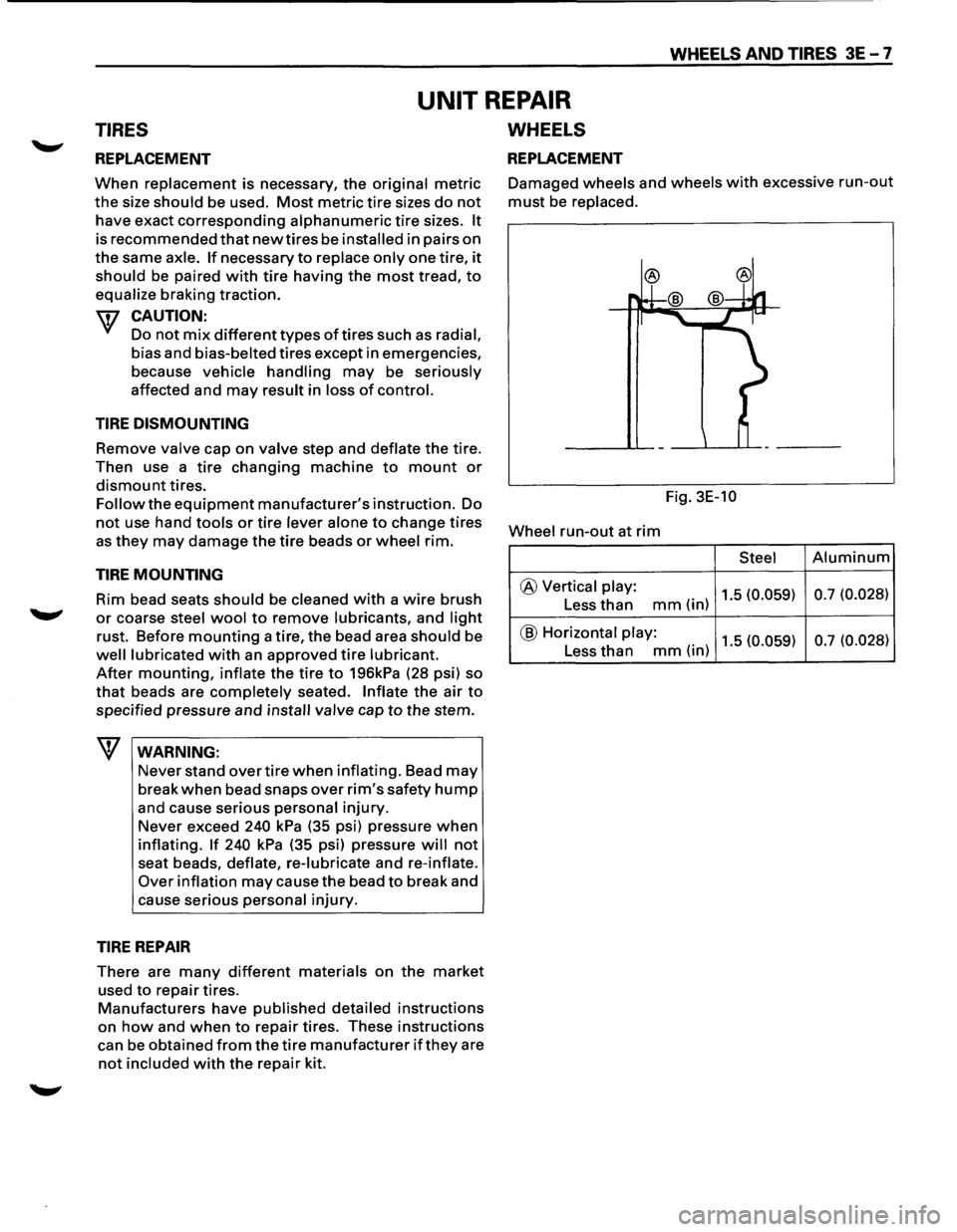
not included with the repair kit. Damaged
wheels and wheels with excessive run-out
must be replaced.
Fig. 3E-10
Wheel
run-out at rim
Steel Aluminum
@ Vertical play: 1.5 (0.059) 0.7
(0.028) Less than mm(in)
@ Horizontal play: 1.5 (0.059) 0.7
(0.028) Less than mm(in)
Page 208 of 1928
3E-8 WHEELS AND TIRES
GENERAL BALANCE PROCEDURE
Deposits of mud, etc. must be cleaned from the inside
of the rim.
The tire should be inspected
for the following: match
mount paint marks, bent rims, bulges, irregular tire
wear, proper
wheel size and inflation pressure. Then
balance according to the equipment manufacturer's
recommendations.
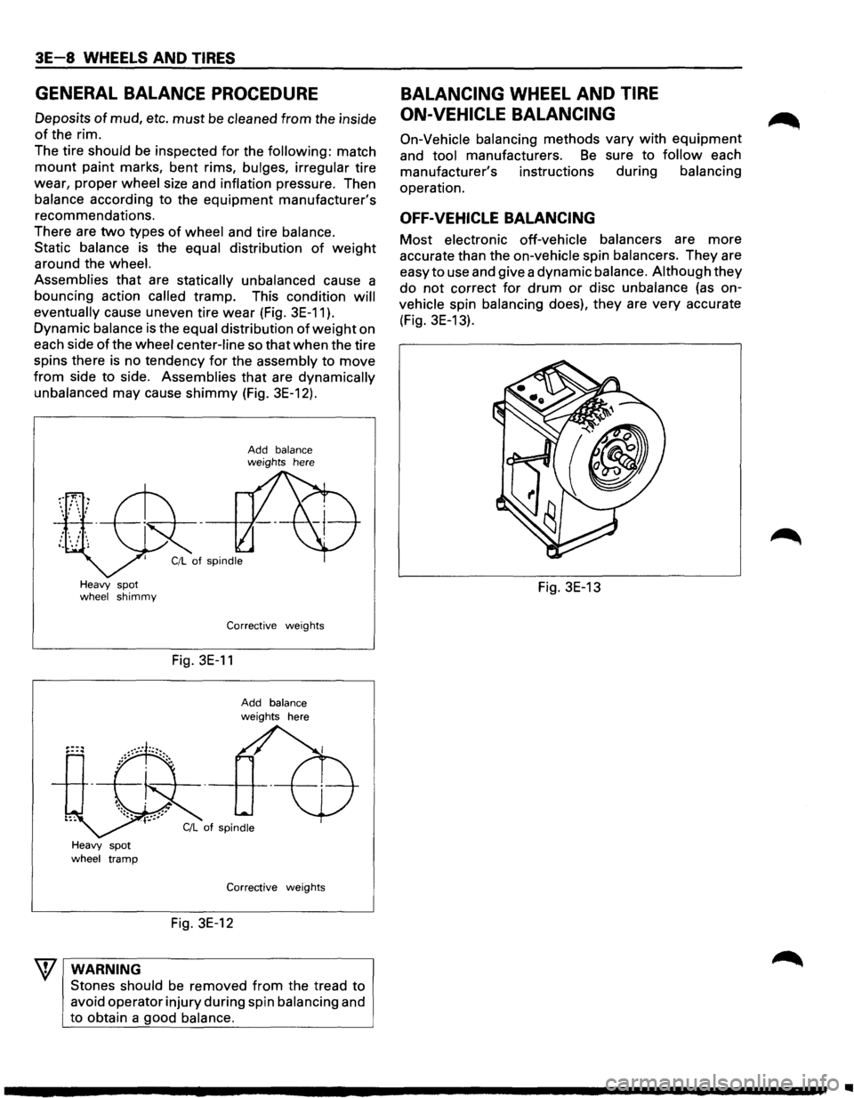
There are
two types of wheel and tire balance.
Static balance is the equal distribution
of weight
around the wheel.
Assemblies
that are statically unbalanced cause a
bouncing action
called tramp. This condition will
eventually
cause uneven tire wear (Fig. 3E-11 ).
Dynamic balance is the equal distribution of weight on
each side
of the wheel center-line so that when the tire
spins there
is no tendency for the assembly to move
from side to side. Assemblies that are dynamically
unbalanced may cause shimmy (Fig. 3E-12).
Heavy spot wheel shimmy
Heavy spot wheel tramp
WARNING
Add balance weights here
Corrective weights
Fig. 3E-11
Add balance
weights here
Corrective weights
Fig. 3E-12
Stones should
be removed from the tread to
avoid operator injury during spin balancing and
to obtain a
good balance.
BALANCING WHEEL AND TIRE
ON-VEHICLE
BALANCING
On-Vehicle balancing methods vary with equipment
and tool manufacturers. Be sure to follow each
manufacturer's instructions during balancing
operation.
OFF-VEHICLE BALANCING
Most electronic off-vehicle balancers are more
accurate than the on-vehicle spin balancers. They are
easy to use and give a dynamic balance. Although
they
do not correct for drum or disc unbalance (as on
vehicle
spin balancing does), they are very accurate
(Fig. 3E-13).
Fig. 3E-13
Page 209 of 1928
WHEELS AND TIRES 3E-9
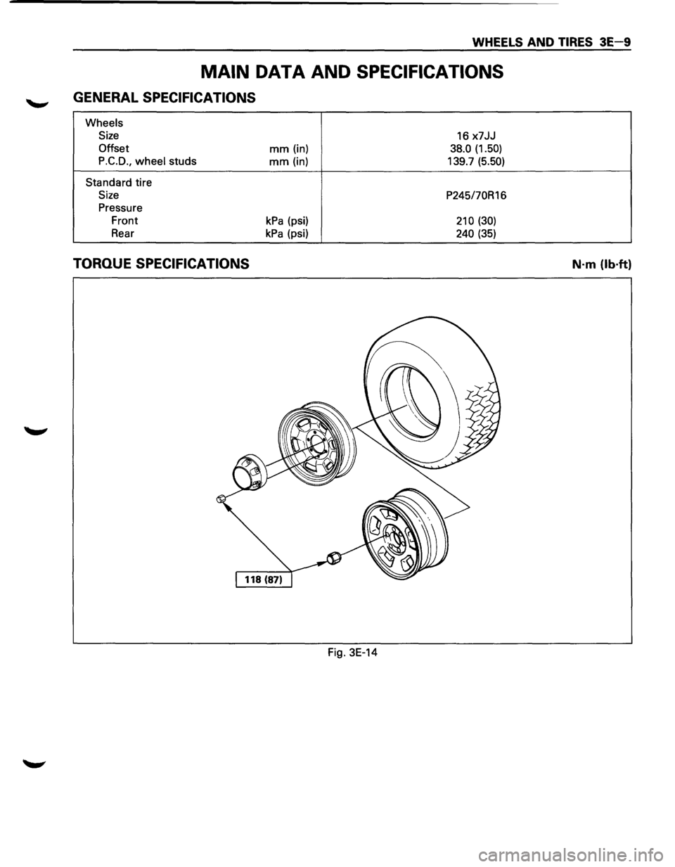
MAIN DATA AND SPECIFICATIONS
GENERAL SPECIFICATIONS
Wheels
Size
16 x7JJ
Offset mm (in) 38.0 (1.50)
P.C.D.,
wheel studs mm (in) 139.7 (5.50)
Standard tire
Size P245/70R16
Pressure
Front
kPa (psi) 210 (30)
Rear kPa (psi) 240 (35)
TORQUE SPECIFICATIONS
Fig. 3E-14
N·m (lb·ft)
Page 245 of 1928
REAR AXLE 48-3
DIAGNOSIS OF REAR AXLE NOISE
Many noises that seem to come from the rear axle
actually
originate from other sources such as tires,
road surface, wheel bearings, engine, transmission,
muffler,
or body drumming. Investigate to find the
source
ofthe noise before disassembling the rear axle.
Rear axles,
like any other mechanical device, are not
absolutely quiet but should be considered quiet unless
some abnormal noise is present.
To make a systematic check
for axle noise, observe the
following:
1. Select a level asphalt road to reduce tire noise and
body drumming.
2. Check rear axle lubricant level to assure correct
level, and then drive the vehicle far enough to
thoroughly warm up the rear axle lubricant.
3. Note the speed at which noise occurs. Stop the
vehicle and put the transmission in neutral. Run
the engine speed
slowly up and down to
determine if the noise is caused by exhaust,
muffler noise, or other engine conditions.
4. Tire noise changes with different road surfaces;
axle noises do not. Temporarily inflate all tires to
344
kPa (50 psi) (for test purposes only). This will
change noise caused by tires but will not affect
noise caused by the rear
axle.
Rear axle nose usually stops when coasting at
speeds under
48 km/h (30 mph); however, tire
noise continues
with a lower tone. Rear axle noise
usually changes when comparing pull and coast,
but tire noise stays about the same.
Distinguish between tire noise and rear
axle noise
by noting
if the noise changes with various
speeds
or sudden acceleration and deceleration.
Exhaust and
axle noise vary under these
conditions,
while tire noise remains constant and
is more pronounced at speeds
of 32 to 48 km/h
(20 to 30 mph). Further check for tire noise by
driving the vehicle
over smooth pavements or dirt
roads (not gravel) with the tires at normal
pressure.
If the noise is caused by tires, it will
change noticeably with changes in road surface.
5. Loose or rough front wheel bearings will cause
noise
which may be confused with rear axle
noise; however, front wheel bearing noise does
not change when comparing drive and coast.
Light application
of the brake while holding
vehicle speed steady
will often cause wheel
bearing noise to diminish. Front wheel bearings
may be checked for noise by jacking up the
wheels and spinning them
or by shaking the
wheels
to determine if bearings are loose.
6. Rear suspension rubber bushings and spring
insulators dampen
out rear axle noise when
correctly installed. Check to see that there is no
link or rod loosened or metal-to-metal contact.
7. Make sure that there is no metal-to-metal contact
between the
floor and the frame.
After the noise has been determined to be in the axle,
the type of axle noise should be determined, in order to
make any necessary repairs.
GEAR NOISE
Gear noise (whine) is audible from 32 to 89 km/h (20 to
55 mph) under four driving conditions.
1. In drive under acceleration or heavy pull.
2. Driving under load or under constant speed.
3. When using enough throttle to keep the vehicle
from driving the engine while the vehicle slows
down gradually (engine still pulls slightly).
4. When coasting with the vehicle in gear and the
throttle closed. The gear noise is
usually more
noticeable between 48 and 64
km/h (30 and 40
mph) and 80 and 89 km/h (50 and 55 mph).
BEARING NOISE
Bad bearings generally produce a rough growl or
grating sound, rather than the whine typical of gear
noise. Bearing noise frequently
"wow-wows" at
bearing rpm, indicating a bad pinion
or rear axle side
bearing. This noise can
be confused with rear wheel
bearing noise.
REAR WHEEL BEARING NOISE
Rear wheel bearing noise continues to be heard while
coasting at low speed with transmission in the neutral.
Noise may diminish by gentle braking. Jack up the rear
wheels, spin them by hand and
listen for noise at the
hubs. Replace any faulty
wheel bearings.
KNOCK AT LOW SPEEDS
Low speed knock can be caused by worn universal
joints or a side gear hub counter bore in the cage that is
worn oversize. Inspect and replace universal joints or
cage and side gears as required.
BACKLASH CLUNK
Excessive clunk on acceleration and deceleration can
be caused by a worn rear axle pinion shaft, a worn
cage, excessive clearance between the axle and the
side gear splines, excessive clearance between the
side gear hub and the counterbore in the cage,
worn
pinion and side gear teeth, worn thrust washers, or
excessive drive pinion and ring gear backlash.
Remove
worn parts and replace as required. Select
close-fitting parts when possible. Adjust pinion and
ring gear backlash.
Page 322 of 1928
SA-2 HYDRAULIC BRAKES
BRAKE SYSTEM DIAGNOSIS
ROAD TESTING THE BRAKES
Brake Test
Brakes should be tested on a dry, clean, reasonably
smooth and
level roadway. A true test of brake
performance cannot be made
if the roadway is
wet, greasy
or covered with loose dirt so that all
tires do not grip the road equally. Testing will also
be adversely affected if the roadway is crowned so
as to throw the weight of the vehicle toward
wheels on one side or if the roadway is so rough
that wheels tend to bounce. Test the brakes at dif
ferent vehicle speeds with both light and heavy
pedal pressure; however, avoid locking the wheels
and sliding the tires. Locked wheels and sliding
tires do not indicate brake efficiency, since heavily
braked but turning wheels will stop the vehicle in
less distance than locked wheels. More tire-to-road
friction is present
with a heavily braked turning tire
then
with a sliding tire.
The standard brake system is designed and
balanced
to avoid locking the wheels except at very high
deceleration
levels.
It
is designed this way because the shortest stopping
distance and best
control is achieved without brake
lock-up.
Because of high deceleration capability, a firmer pedal
may be felt at higher deceleration levels.
External Conditions That Affect Brake
Performance
1.
2.
3.
Tires: Tires having unequal contact and grip on
the road
will cause unequal braking. Tires must
be equally inflated, identical in size, and the tread
pattern
of right and left tires must be approxi
mately equal.
Vehicle loading:
A heavily loaded vehicle requires
more braking effort.
Wheel Alignment: Misalignment of the wheels,
particularly
in regard to excessive camber and
caster,
will cause the brakes to pull to one side.
BRAKE FLUID LEAKS
With engine running at idle and the transmission in
"Neutral", depress the brake pedal and hold a constant
foot pressure on the pedal. If pedal gradually falls
away with the constant pressure, the hydraulic system
may be leaking.
Check the master cylinder fluid level. While a slight
drop in reservoir level will result from normal lining
wear, an abnormally low level in reservoir indicates a
leak in the system. The hydraulic system may be
leaking internally as well as externally. Refer to
"Master Cylinder Inspection". Also, the system may
appear
to pass this test but still have slight leakage. If
fluid level
is normal, check the vacuum booster
push rod
length. If an incorrect length push rod is
found, adjust
or replace the push rod. Check the
brake
pedal travel and the parking brake adjust
ment.
When checking the
fluid level, the master cylinder fluid
level
may be low from the "MAX" mark if the front and
rear
linings are worn. This is not abnormal.
WARNING LIGHT OPERATION
When the ignition switch is in the START position,
the
"BRAKE" warning light should glow and go off
when the ignition switch returns to the ON position.
The
following conditions will activate the "BRAKE"
light:
1. Parking brake applied. The light should be on
whenever the parking brake is applied and the
ignition switch is on.
2. Low fluid level. A low fluid level in the master
cylinder will turn the "BRAKE" light on (Except
Rear
Wheel Antilock Brake System (RWAL)
model).
3. During engine cranking the "BRAKE" light
should
remain on. This notifies the driver that
the warning circuit is operating properly.
4. In the event of a front or rear system malfunc
tion (RWAL model only).
5. In the event of RWAL malfunction (RWAL
model only. Refer to Section 5A3).
ANTILOCK BRAKE SYSTEM (RWAL or
ABS}
Refer to Section 5A3 or 5A4 for inspection and di
agnosis procedure of the hydraulic unit.
..
Page 323 of 1928
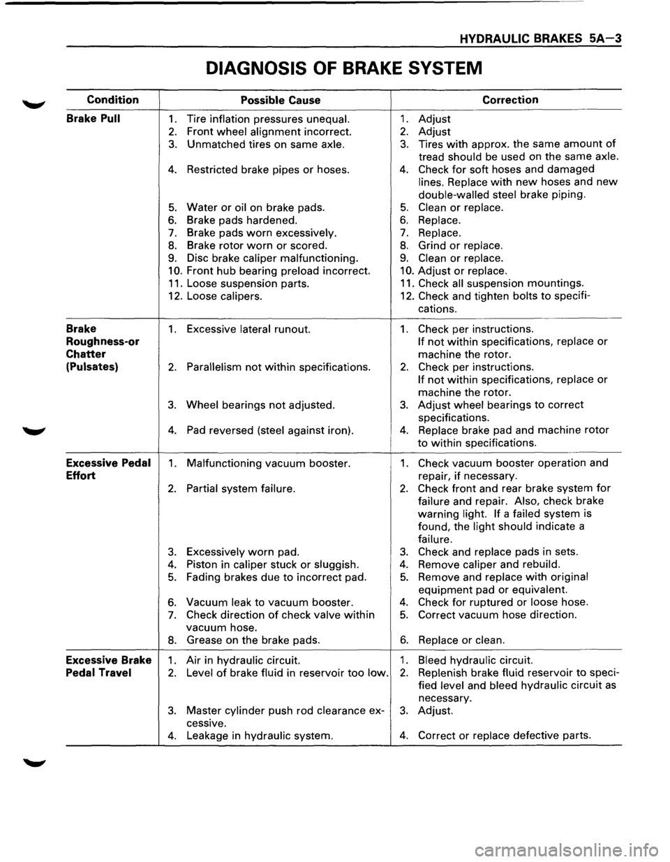
HYDRAULIC BRAKES 5A-3
DIAGNOSIS OF BRAKE SYSTEM
Condition
Possible Cause Correction
Brake
Pull 1. Tire inflation pressures unequal. 1. Adjust
2. Front wheel alignment incorrect. 2. Adjust
3. Unmatched tires on same axle. 3. Tires with approx. the same amount of
tread should be used on the same axle.
4. Restricted brake pipes or hoses. 4. Check for soft hoses and damaged
lines. Replace with new hoses and new
double-walled steel brake piping.
5. Water or oil on brake pads. 5. Clean or replace.
6. Brake pads hardened. 6. Replace.
7. Brake pads worn excessively. 7. Replace.
8. Brake rotor worn or scored. 8. Grind or replace.
9. Disc brake caliper malfunctioning. 9. Clean or replace.
10. Front hub bearing preload incorrect. 10. Adjust or replace.
11. Loose suspension parts. 11. Check all suspension mountings.
12. Loose
calipers. 12. Check and tighten bolts to specifi-
cations.
Brake 1. Excessive lateral runout. 1. Check per instructions.
Roughness-or If not within specifications, replace or
Chatter machine the rotor.
(Pulsates) 2. Parallelism not within specifications. 2. Check per instructions.
If not within specifications, replace or
machine the rotor.
3. Wheel bearings not adjusted. 3. Adjust wheel bearings to correct
specifications.
4. Pad reversed (steel against iron). 4. Replace brake pad and machine rotor
to within specifications.
Excessive Pedal 1. Malfunctioning vacuum booster. 1. Check vacuum booster operation and
Effort repair, if necessary.
2. Partial system failure. 2. Check front and rear brake system for
failure and repair. Also, check brake
warning
light. If a failed system
is
found, the
light should indicate a
failure.
3. Excessively worn pad. 3. Check and replace pads in sets.
4. Piston in caliper stuck or sluggish. 4. Remove caliper and rebuild.
5. Fading brakes due to incorrect pad. 5. Remove and replace with original
equipment pad or equivalent.
6. Vacuum leak to vacuum booster. 4. Check for ruptured or loose hose.
7. Check direction of check valve within 5. Correct vacuum hose direction.
vacuum hose.
8. Grease on the brake pads. 6. Replace or clean.
Excessive Brake 1. Air in hydraulic circuit. 1. Bleed hydraulic circuit.
Pedal Travel 2. Level of brake fluid in reservoir too low. 2. Replenish brake fluid reservoir to speci-
fied
level and bleed hydraulic circuit as
necessary.
3. Master cylinder push rod clearance ex-3. Adjust.
cessive.
4. Leakage in hydraulic system. 4. Correct or replace defective parts.
Page 434 of 1928
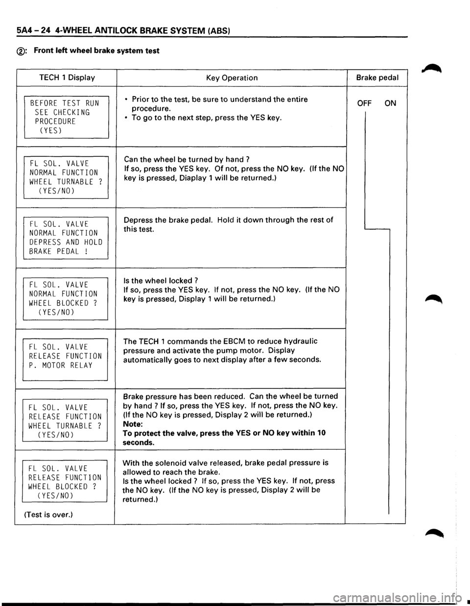
5A4-24 4-WHEEL ANTILOCK BRAKE SYSTEM (ABS)
®: Front left wheel brake system test
TECH 1 Display
Key Operation Brake
pedal
BEFORE TEST RUN • Prior to the test, be sure to understand the entire OFF ON
SEE CHECKING procedure.
PROCEDURE • To go to the next step, press the YES key.
(YES)
FL SOL. VALVE Can the wheel be turned by hand?
NORMAL FUNCTION If so, press the YES key. Of not, press the NO key. (lfthe NO
WHEEL TURNABLE ? key is pressed, Diaplay 1 will be returned.)
(YES/NO)
FL SOL. VALVE Depress the brake pedal. Hold it down through the rest of
NORMAL FUNCTION this test.
DEPRESS AND HOLD
BRAKE PEDAL !
FL SOL. VALVE Is the wheel locked ?
NORMAL FUNCTION If so, press the YES key. If not, press the NO key. (If the NO
WHEEL BLOCKED ? key is pressed, Display 1 will be returned.)
(YES/NO)
FL SOL. VALVE The TECH 1 commands the EBCM to reduce hydraulic
RELEASE FUNCTION pressure and activate the pump motor. Display
p. MOTOR RELAY automatically goes to next display after a few seconds.
Brake pressure has been reduced. Can the wheel be turned
FL SOL. VALVE by hand ? If so, press the YES key. If not, press the NO key.
RELEASE FUNCTION (If the NO key is pressed, Display 2 will be returned.)
WHEEL TURNABLE ? Note:
(YES/NO) To protect the valve, press the YES or NO key within 10
seconds.
FL SOL. VALVE With the solenoid valve released, brake pedal pressure is
RELEASE FUNCTION allowed to reach the brake.
WHEEL BLOCKED ? Is the wheel locked ? If so, press the YES key. If not, press
(YES/NO) the NO key. (If the NO key is pressed, Display 2 will be
returned.)
(Test is over.)
•