light ISUZU TROOPER 1995 Workshop Manual
[x] Cancel search | Manufacturer: ISUZU, Model Year: 1995, Model line: TROOPER, Model: ISUZU TROOPER 1995Pages: 1928
Page 1796 of 1928
1o-38 BODY
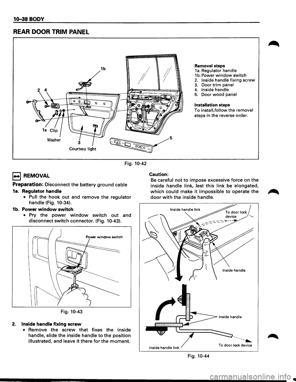
REAR DOOR TRIM PANEL
1b
~
Removal steps 1a. Regulator handle 1 b. Power window switch 2. Inside handle fixing screw
3. Door trim panel
!I
I ;I
Courtesy light
Fig. 10-42
1+•1 REMOVAL
Preparation: Disconnect the battery ground caQie
1a. Regulator handle
• Pull the hook out and remove the regulator
handle
(Fig. 10-34).
1b. Power window switch
• Pry the power window switch out and
disconnect switch connector. (Fig.
10-43).
Fig. 10-43
2. Inside handle fixing screw
• Remove the screw that fixes the inside
handle, slide the inside handle to the position
illustrated, and leave it there for the moment.
5
Caution:
4. Inside handle 5. Door wood panel
Installation steps
To install, follow the removal
steps in the reverse order.
Be careful not to impose excessive force on the
inside
handle link, lest this link be elongated,
which could make it impossible to operate the
door with the inside handle.
Inside handle link
Fig. 10-44
---~
To door lock device
Page 1814 of 1928
10-56 BODY
BODY SIDE
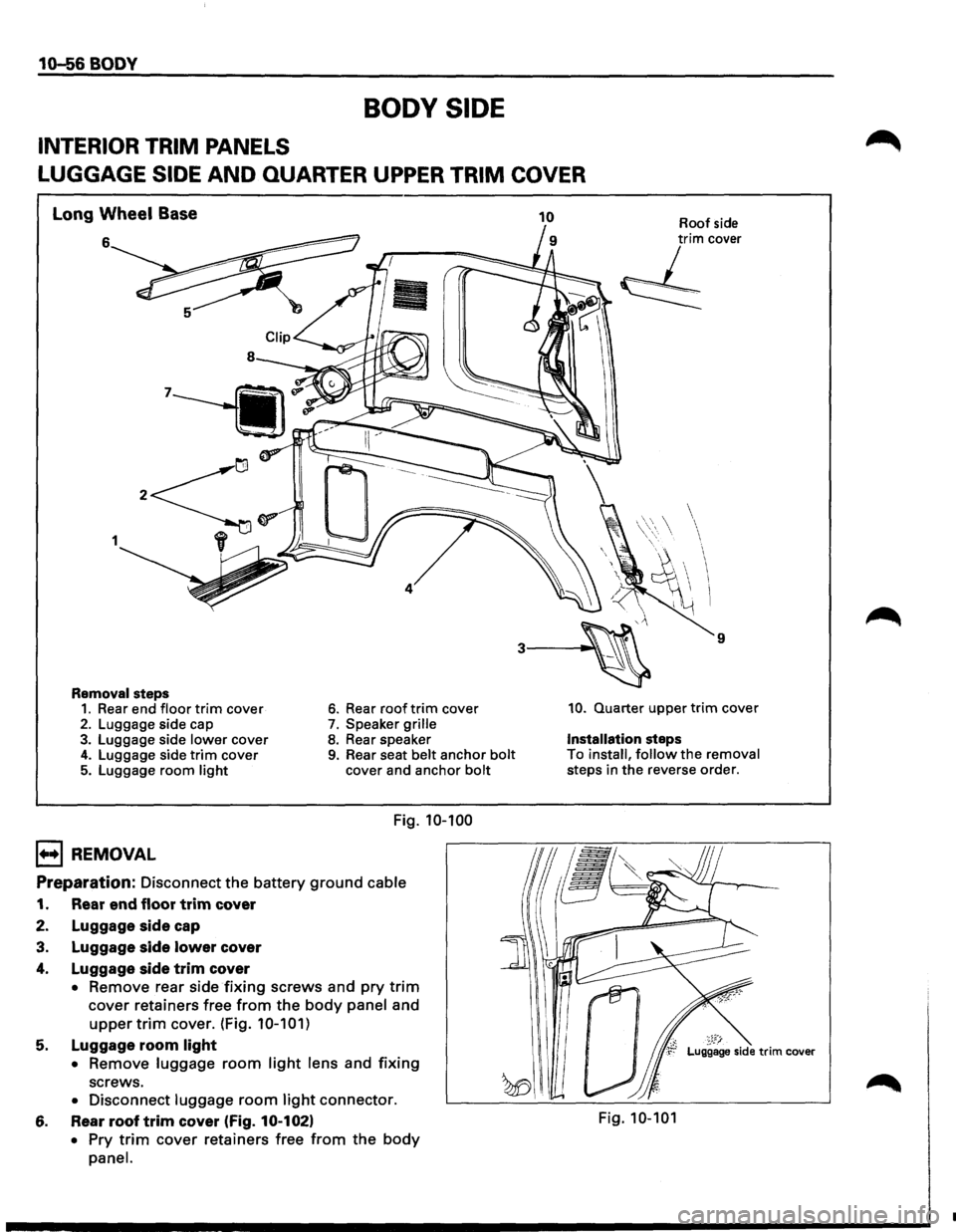
INTERIOR TRIM PANELS
LUGGAGE
SIDE AND QUARTER UPPER TRIM COVER
Long Wheel Base
6
1
Removal steps 1. Rear end floor trim cover 2. Luggage side cap 3. Luggage side lower cover 4. Luggage side trim cover 5. Luggage room light
1+•1 REMOVAL
6. Rear roof trim cover
7. Speaker grille 8. Rear speaker 9. Rear seat belt anchor bolt cover and anchor bolt
Fig. 10-100
Preparation: Disconnect the battery ground cable
1. Rear end floor trim cover
2. Luggage side cap
3. Luggage side lower cover
4. Luggage side trim cover
• Remove rear side fixing screws and pry trim
cover retainers free from the body panel and
upper trim cover. (Fig. 10-101)
5. Luggage room light
• Remove luggage room light lens and fixing
screws.
• Disconnect luggage room light connector.
6. Rear roof trim cover (Fig. 10-102)
• Pry trim cover retainers free from the body
panel.
Roof side trim cover
, _ _.,,..~
~
9
10. Quarter upper trim cover
Installation steps
To install, follow the removal
steps in
the reverse order.
~~F:r Luggage side trim cover
Fig. 10-101
•
Page 1816 of 1928
10-58 BODY
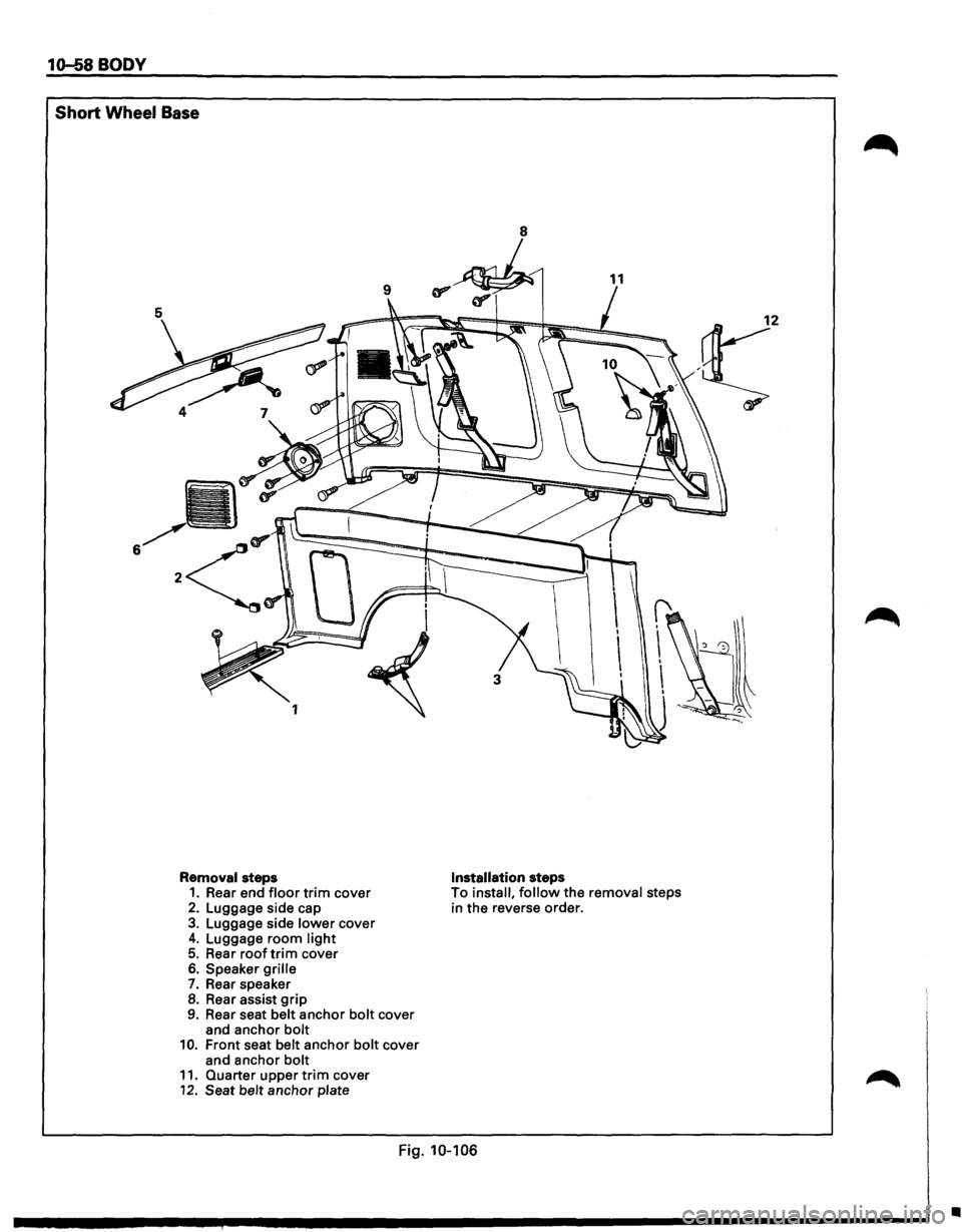
Short Wheel Base
Removal steps 1. Rear end floor trim cover 2. Luggage side cap 3. Luggage side lower cover 4. Luggage room light 5. Rear roof trim cover 6. Speaker grille
7. Rear speaker 8. Rear assist grip 9. Rear seat belt anchor bolt cover
and anchor bolt 10. Front seat belt anchor bolt cover
and anchor bolt 11. Quarter upper trim cover 12. Seat belt anchor plate
Installation steps To install, follow the removal steps
in the reverse order.
Fig. 10-106
•
Page 1817 of 1928
1+•1 REMOVAL
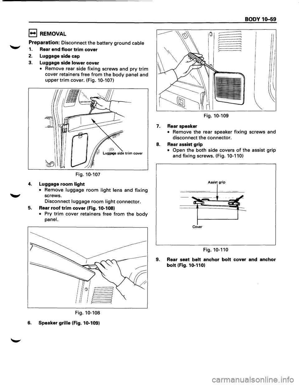
Preparation: Disconnect the battery ground cable
1. Rear end floor trim cover
2. Luggage side cap
3. Luggage side lower cover
• Remove rear side fixing screws and pry trim
cover retainers free from the body panel and
upper trim cover. (Fig. 10-107)
I
w\\1
Fig. 10-107
4. Luggage room light
• Remove luggage room light lens and fixing
~ screws.
Disconnect
luggage room light connector.
5. Rear roof trim cover (Fig. 10-108)
•
Pry trim cover retainers free from the body
panel.
Fig. 10-108
6. Speaker grille (Fig. 10-109)
Fig. 10-109
7. Rear speaker
BODY 10-59
I
I I
~
• Remove the rear speaker fixing screws and
disconnect
the connector.
8. Rear assist grip
• Open the both side covers of the assist grip
and fixing screws. (Fig. 10-110)
Assist grip
Cover
Fig. 10-110
9. Rear seat belt anchor bolt cover and anchor
bolt (Fig. 10-110)
Page 1827 of 1928
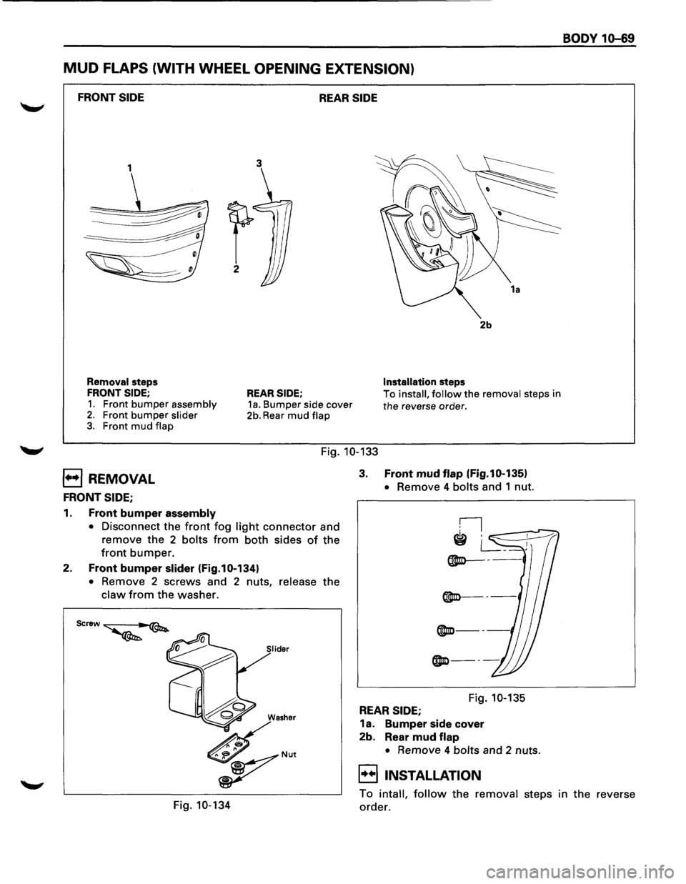
MUD FLAPS (WITH WHEEL OPENING EXTENSION)
FRONT SIDE REAR SIDE
1
Removal steps
FRONT SIDE;
1. Front bumper assembly 2. Front bumper slider 3. Front mud flap
3
REAR SIDE; 1a. Bumper side cover
2b. Rear mud flap
2b
Installation steps
To
install, follow the removal steps in
the reverse order.
Fig. 10-133
E) REMOVAL
FRONT SIDE;
1. Front bumper assembly
• Disconnect the front fog light connector and
remove the 2 bolts from both sides of the
front bumper.
2. Front bumper slider (Fig.10-134)
• Remove 2 screws and 2 nuts, release the
claw from the washer.
3. Front mud flap (Fig.10-135l
• Remove 4 bolts and 1 nut.
®Io---
Fig. 10-135
REAR SIDE;
1a. Bumper side cover
2b. Rear mud flap
• Remove 4 bolts and 2 nuts.
EIINSTALLATION
BODY 10-69
Fig. 10-134
To intall, follow the removal steps in the reverse
order.
Page 1830 of 1928
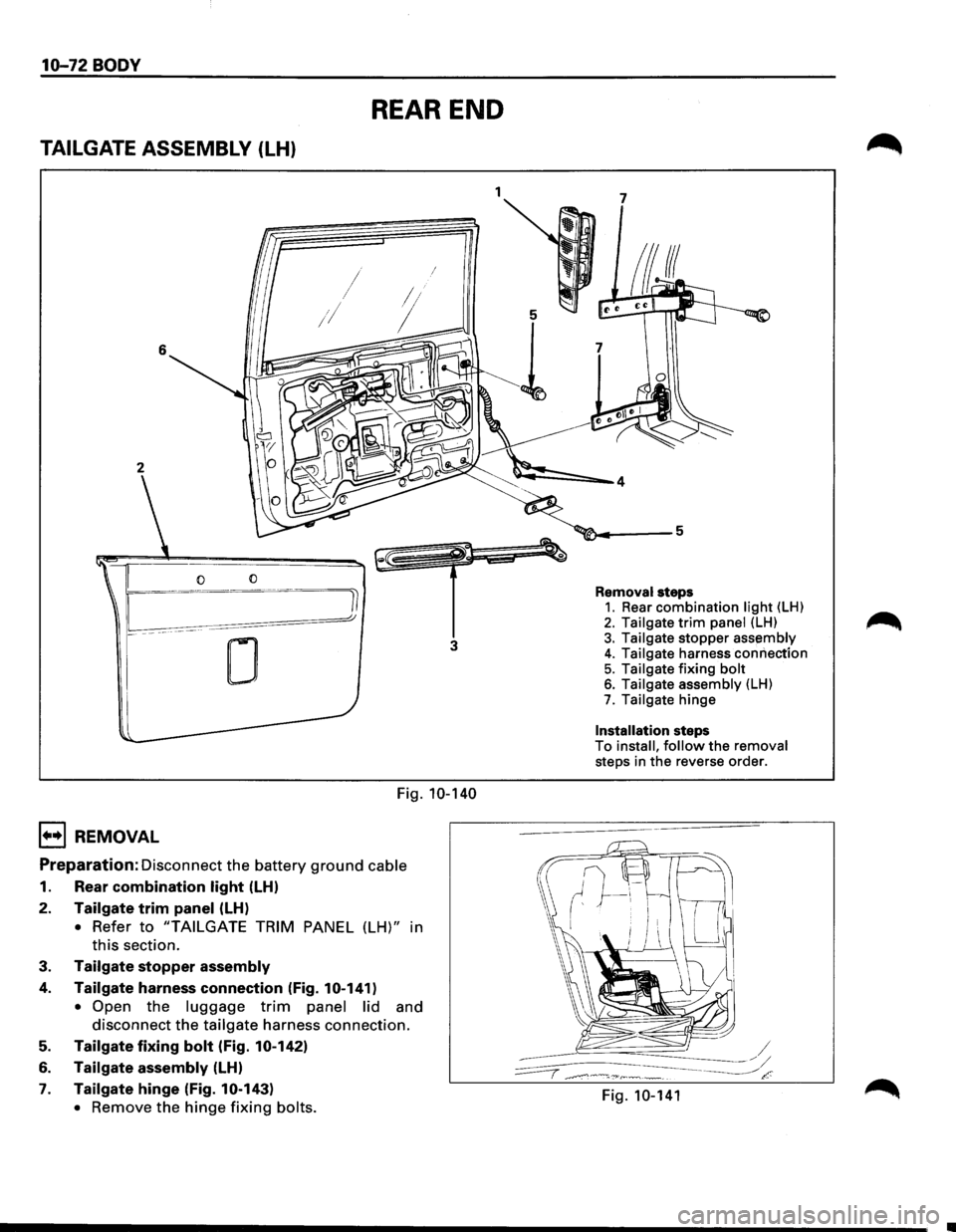
10-72 BODY
REAR END
TAILGATE ASSEMBLY (LH)
6
2
0
0
3
Fig. 10-140
1••1 REMOVAL
Preparation: Disconnect the battery ground cable
1. Rear combination light (LH)
2. Tailgate trim panel (LH)
• Refer to "TAILGATE TRIM PANEL (LH)" in
this section.
3. Tailgate stopper assembly
4. Tailgate harness connection (Fig. 10-141)
• Open
the luggage trim panel lid and
disconnect
the tailgate harness connection.
5. Tailgate fixing bolt (Fig. 10-142)
6. Tailgate assembly (LH)
7. Tailgate hinge (Fig. 10-143)
•
Remove the hinge fixing bolts.
1 7
Removal steps 1. Rear combination light (LH)
2. Tailgate trim panel (LH) 3. Tailgate stopper assembly
4. Tailgate harness connection 5. Tailgate fixing bolt 6. Tailgate assembly (LH) 7. Tailgate hinge
Installation steps
To
install, follow the removal steps in the reverse order.
Fig. 10-141
Page 1831 of 1928
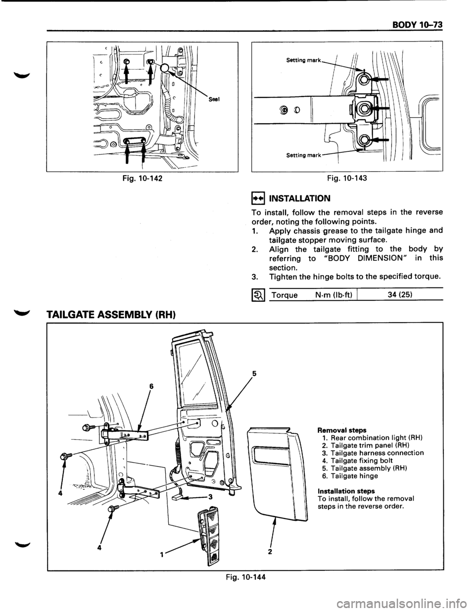
Saal
Fig. 10-142
~ TAILGATE ASSEMBLY (RH)
4
1
BODY 10-73
Setting mark
Setting mark
Fig. 10-143
I••IINSTALLATION
To install, follow the removal steps in the reverse
order,
noting the fol!lowing points.
1. Apply chassis grease to the tailgate hinge and
tailgate stopper
moving surface.
2. Align the tailgate fitting to the body by
referring to "BODY DIMENSION" in this
section.
3. Tighten the hinge bolts to the specified torque.
~~~ Torque
5
I
2
Fig. 10-144
N·m (lb·ftl J 34 (25)
Removal steps 1. Rear combination light (RH) 2. Tailgate trim panel (RH)
3. Tailgate harness connection 4. Tailgate fixing bolt 5. Tailgate assembly (RH)
6. Tailgate hinge
Installation steps To install, follow the removal steps in the reverse order.
Page 1832 of 1928
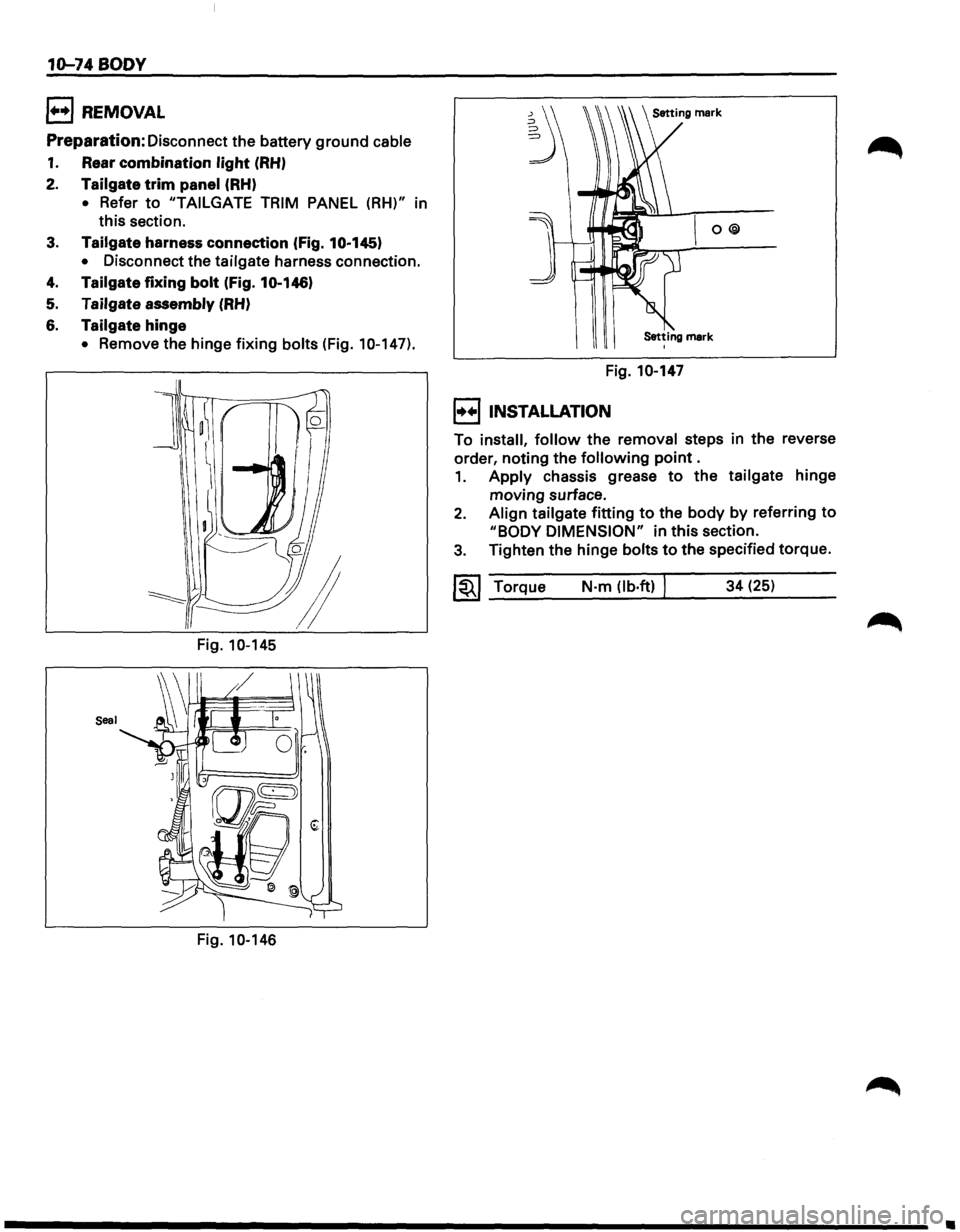
10-74 BODY
1++1 REMOVAL
Preparation: Disconnect the battery ground cable
1. Rear combination light (RH)
2. Tailgate trim panel (RH)
• Refer to "TAILGATE TRIM PANEL (RH)" in
this section.
3. Tailgate harness connection (Fig. 10·145)
• Disconnect the tailgate harness connection.
4. Tailgate fixing bolt (Fig. 10.146)
5. Tailgate assembly (RH)
6. Tailgate hinge
• Remove the hinge fixing bolts (Fig. 10-147).
Fig.
10-145
Seal
Fig. 10-146
~ O@
Setting mark I
Fig. 10-147
I••IINSTALLATION
To install, follow the removal steps in the reverse
order, noting the
following point .
1. Apply chassis grease to the tailgate hinge
moving surface.
2. Align tailgate fitting to the body by referring to
"BODY DIMENSION" in this section.
3. Tighten the hinge bolts to the specified torque.
~~~ Torque N·m (lb·ft) I 34 (25)
•
Page 1840 of 1928
10-82 BODY
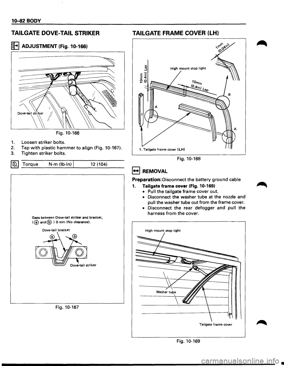
TAILGATE DOVE-TAIL STRIKER
I~FI ADJUSTMENT (Fig. 10-166)
Dove-tail striker 1/
\~!
Fig. 10-166
1. Loosen striker bolts.
2. Tap with plastic hammer to align (Fig. 10-167).
3. Tighten striker bolts.
~~~ Torque N·m (lb.in) I 12 (104)
Gaps between Dove-tail striker and bracket,
!@and@ ) 0 mm (No clearance).
Dove-tail bracket
Fig. 10-167
TAILGATE FRAME COVER (LH)
0. j High mount stop light
1. Tailgate frame cover (LH)
Fig. 10-168
1+•1 REMOVAL
Preparation:
Disconnect the battery ground cable
1. Tailgate frame cover (Fig. 10-169}
• Pull the tailgate frame cover out.
• Disconnect the washer tube at the nozzle and
pull the washer tube out from the frame cover.
• Disconnect the rear defogger and pull the
harness
from the cover.
High mount stop light
Tailgate frame cover
Fig. 10-169
•
Page 1869 of 1928
BODY 10-111
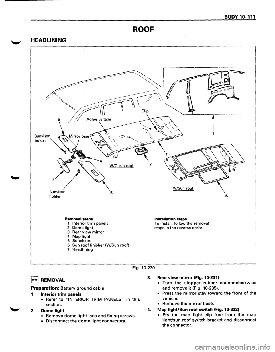
ROOF
HEADLINING
~---~~I
~r CUp ''-. _ __j
5 1 Adh.,;,;, tap• . T
1
W /0 sun roof 2
Sunvisor
holder 5
Removal steps 1. Interior trim panels 2. Dome light 3. Rear view mirror 4. Map light 5. Sunvisors 6. Sun roof finisher (W/Sun roof) 7. Headlining W/Sun
roof
Installation steps To install, follow the removal steps
in the reverse order. 6
Fig. 10-230
1••1 REMOVAL
Preparation: Battery ground cable
1. Interior trim panels
•
Refer to "INTERIOR TRIM PANELS" in this
section.
2. Dome light
• Remove dome light lens and fixing screws.
• Disconnect the dome light connectors.
3. Rear view mirror (Fig. 10-231)
• Turn the stopper rubber counterclockwise
and remove
it (Fig. 10-235).
• Press the mirror stay toward the front of the
vehicle.
•
Remove the mirror base.
4. Map light/Sun roof switch (Fig. 10-232)
• Pry the map light clip free from the map
light/sun roof switch bracket and disconnect
the connector.