light ISUZU TROOPER 1995 Workshop Manual
[x] Cancel search | Manufacturer: ISUZU, Model Year: 1995, Model line: TROOPER, Model: ISUZU TROOPER 1995Pages: 1928
Page 1614 of 1928
9B-30 CRUISE CONTROL
1. Front console assembly
• Remove four screws.
• Remove the transmission shift lever knob.
• Remove the transfer shift lever knob.
• Disconnect the seat heater switch connectors
(If so equipped).
• Disconnect the "POWER & WINTER" switch
connectors (A/T only).
2. Lower cluster assembly
• Remove three screws.
• Disconnect the cigar lighter connectors.
• Remove the cigar lighter illumination bulb
socket.
• Disconnect the ashtray illumination bulb
connector.
3. Instrument panel driver lower cover
• Remove the engine hood opener.
• Remove three screws and clip.
•
Disconnect four fasteners.
4. Steering cowl
• Remove seven screws.
5. Starter switch
• Disconnect the connector.
• Remove the screw.
8 INSTALLATION
To install, follow the removal steps in the reverse
order noting the following point.
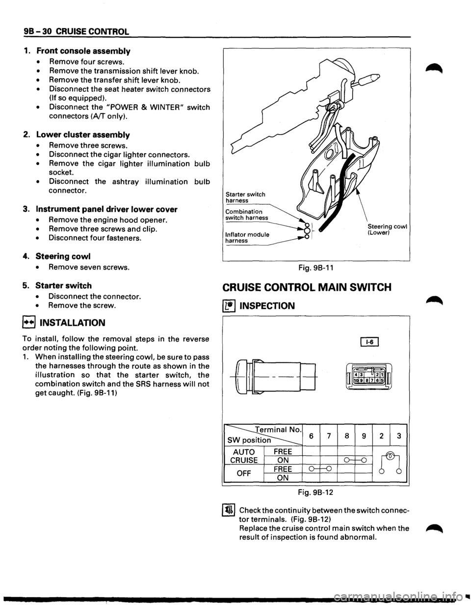
1. When installing the steering cowl, be sure to pass
the harnesses
through the route as shown in the
illustration so that the starter switch, the
combination switch and the SRS harness will not
get caught. (Fig. 98-11)
Starter switch
harness
Combination
switch harness
l._n!~~~o!_ module __..o .~ ~
Fig. 98-11
Steering cowl (Lower)
CRUISE CONTROL MAIN SWITCH
(1!1 INSPECTION
OI1
r-="'
-L
r= t-------uii4J~l "ltl1 u
l
1111ilr9Tsl7lels .,
:::o.,..o-
~ s 6 7 8 9 2 3
AUTO FREE
n
CRUISE ON ()-1---n
OFF FREE o-f--0
ON
Fig. 98-12
ltjl Check the continuity between the switch connec
tor terminals. (Fig. 98-12)
Replace the cruise control main switch when the ~
result of inspection is found abnormal.
Page 1615 of 1928
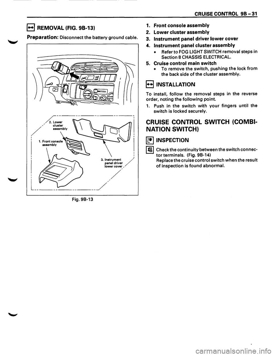
B REMOVAL (FIG. 98-13)
Preparation: Disconnect the battery ground cable.
Fig.
98-13
CRUISE CONTROL 98-31
1. Front console assembly
2. Lower cluster assembly
3. Instrument panel driver lower cover
4. Instrument panel cluster assembly
• Refer to FOG LIGHT SWITCH removal steps in
Section 8 CHASSIS ELECTRICAL.
5. Cruise control main switch
• To remove the switch, pushing the lock from
the back side of the cluster assembly.
B INSTALLATION
To install, follow the removal steps in the reverse
order, noting the
following point.
1. Push in the switch with your fingers until the
switch is locked securely.
CRUISE CONTROL SWITCH (COMBI
NATION SWITCH)
(b!] INSPECTION
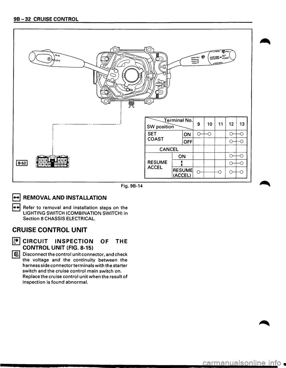
I till Check the continuity between the switch connec
tor terminals. (Fig. 98-14)
Replace the cruise control switch when the result
of inspection is found abnormal.
Page 1616 of 1928
98-32 CRUISE CONTROL
Fig. 98-14
B REMOVAL AND INSTALLATION
l•+l Refer to removal and installation steps on the
LIGHTING SWITCH (COMBINATION SWITCH) in
Section 8 CHASSIS ELECTRICAL.
CRUISE CONTROL UNIT
~CIRCUIT INSPECTION OF THE
CONTROL UNIT (FIG. 8-15)
l t!ll Disconnect the control unit connector, and check
the voltage and the continuity between the
harness side connectorterminals with the starter
switch and the cruise control main switch on.
Replace the cruise control unit when the result of
inspection is found abnormal.
~-s
SET
ON
COAST
OFF
CANCEL
ON
RESUME
: ACCEL RESUME
(ACCEL) 9
10 11 12
13
o--'-0 o--f-0
o--f-0
o--'-0
o--'-0
o----o
•
Page 1620 of 1928
9B-36 CRUISE CONTROL
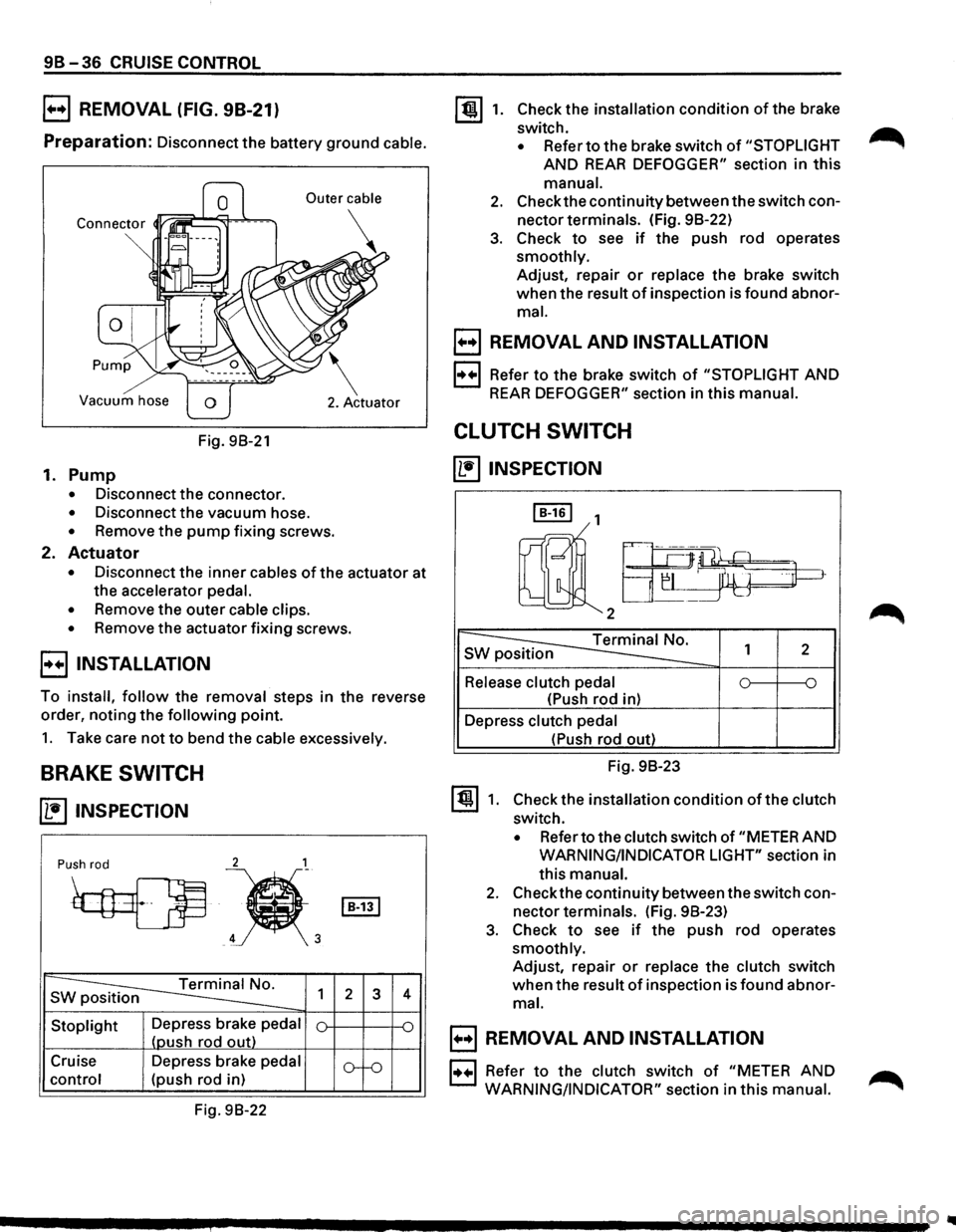
B REMOVAL (FIG. 98-21)
Preparation: Disconnect the battery ground cable.
Vacuum hose
Fig. 98-21
1. Pump
• Disconnect the connector.
• Disconnect the vacuum hose.
• Remove the pump fixing screws.
2. Actuator
• Disconnect the inner cables of the actuator at
the accelerator
pedal.
•
Remove the outer cable clips.
• Remove the actuator fixing screws.
E) INSTALLATION
To install, follow the removal steps in the reverse
order, noting
the following point.
1. Take care not to bend the cable excessively.
BRAKE SWITCH
~ INSPECTION
2 1
Push rod
~
~'
s ~ 1
Stoplight Depress brake pedal
(oush rod out)
Cruise Depress brake
pedal
control (push rod in)
Fig. 98-22
I B-131
2 3
o--o
4
~1. Check the installation condition of the brake
switch.
• Refer to the brake switch of "STOPLIGHT
AND REAR DEFOGGER" section in this
manual.
2. Check the continuity between the switch con
nector terminals. (Fig. 98-22)
3. Check to see if the push rod operates
smoothly. Adjust, repair
or replace the brake switch
when the result
of inspection is found abnor
mal.
B REMOVAL AND INSTALLATION
1·++·1 Refer to the brake switch of "STOPLIGHT AND
REAR DEFOGGER" section in this manual.
CLUTCH SWITCH
~INSPECTION
I B-161 1
rnll2a-~~
~ s 1 2
Release clutch pedal 0 ~ ~
(Push rod in)
Depress
clutch pedal
~1.
(Push rod out)
Fig. 98-23
Check the installation
condition of the clutch
switch.
• Refer to the clutch switch of "METER AND
WARNING/INDICATOR LIGHT" section in
this
manual.
2. Check the continuity between the switch con
nector terminals. (Fig. 98-23)
3. Check to see if the push rod operates
smoothly. Adjust, repair
or replace the clutch switch
when the result of inspection is found abnor
mal.
B REMOVAL AND INSTALLATION
1••1 Refer to the clutch switch of "METER AND ...-...
WARNING/INDICATOR"
section in this manual. ,...........
Page 1622 of 1928
![ISUZU TROOPER 1995 Workshop Manual 98-38 CRUISE CONTROL
VEHICLE SPEED SENSOR (INCORPO
RATED IN SPEEDOMETER)
(1!] INSPECTION
GND GND
SEN 4P
~
I Red(+) Black(-) Black(-) Red(+)
a
I
4P GND 4P GND
4P-GND
13.5K-16.5K 00
Note:](/img/61/57183/w960_57183-1621.png "ISUZU TROOPER 1995 Workshop Manual 98-38 CRUISE CONTROL
VEHICLE SPEED SENSOR (INCORPO
RATED IN SPEEDOMETER)
(1!] INSPECTION
GND GND
SEN 4P
~
I Red(+) Black(-) Black(-) Red(+)
a
I
4P GND 4P GND
4P-GND
13.5K-16.5K 00
Note:")
98-38 CRUISE CONTROL
VEHICLE SPEED SENSOR (INCORPO
RATED IN SPEEDOMETER)
(1!] INSPECTION
GND GND
SEN 4P
~
I Red(+) Black(-) Black(-) Red(+)
a
I
4P GND 4P GND
4P-GND
13.5K-16.5K 00
Note: Use an analog type circuit tester.
Fig. 98-25
~~~ Removethespeedometerfromthemeterassem-DIODE
bly, and measure the resistance value between
the
terminals. (Fig. 98-26) IL•IINSPECTION
Replace the speedometer assembly when the
result of inspection is found abnormal.
B REMOVAL AND INSTALLATION
1•+1 Refer to Section 8 "METER AND WARNING/
INDICATOR LIGHT"
for vehicle speed sensor
removal and installation steps.
I B-451
~
Terminal No. 1 2
Connection A
G 0
pattern
0 G 8
Fig.
98-26
I~~ There should be continuity in either A or 8 when
a circuit tester is connected
with diode terminal.
(Fig. 98-26)
Replace the diode when the result of inspection
is
found abnormal.
..
Page 1698 of 1928

9J-74 Supplemental Restraint System
---~
DTC31 \"'
DRIVER LOOP ENERGY RESERVE FEED OPEN
CIRCUIT DESCRIPTION
During the "Continuous Monitoring" tests the DERM
monitors the
voltage at "Driver Source Sense" terminal
"AS." When the circuit is operating normally the
measured voltage will be slightly less than "Driver 36
VLR."
If the "Driver 36 VLR" circuit opens the voltage
measured at "Driver Source Sense" will decrease to
slightly less than "Ignition 1" voltage. When the voltage
measured at "Driver Source Sense" is within a specified
range of
"Ignition 1" for SOO milliseconds DTC 31 is set.
DTC WILL SET WHEN
The voltage measured at "Driver Source Sense" terminal
"AS"
is within a specified range of "Ignition 1" for SOO
milliseconds. This test is run every 100 milliseconds
during "Continuous Monitoring" tests.
ACTION TAKEN
DERM turns "ON" the "AIR BAG" warning lamps and sets
a diagnostic
trouble code.
DTC WILL CLEAR WHEN
The voltage measured at "Driver Source Sense" terminal
"AS"
is outside the specified range of "Ignition 1" which
sets the diagnostic
trouble code, for SOO milliseconds.
TO IGNITION SWITCH
FUSE! SRS C-24 lOA , ... R D
FUSE SRS C-23 IDA , ...
DTC CHART TEST DESCRIPTION
Number(s) below refer to step number(s) on the
diagnostic chart.
2. This test checks for an open in the "Driver 36VLR"
circuit.
3. This test checks for a high resistance, but not an
open, in the "Driver Source Sense" circuit.
4. This test checks for a short from the "Driver Source
Sense" circuit to 8+.
s. This test determines whether the malfunction is due
to the
dual pole arming sensor.
DIAGNOSTIC AIDS
An intermittent condition is likely to be caused by a poor
connection at arming sensor
terminal "4" or "6", poor
connection at DERM
terminal "A4" or "AS", an open in
CKT 1811 or CKT 1812, or an open inside the dual pole
arming sensor.
IGNITION1
IGNITION1
DRIVER SOURCE SENSE DRIVER 38VLR PASS.3eVLR PASS. SOURCE SENSE
PASS SIDE HIGH
PASS SIDE LOW
SPARE/LPS
SERIAL DATA
SRS INDICATOR
..
Page 1704 of 1928
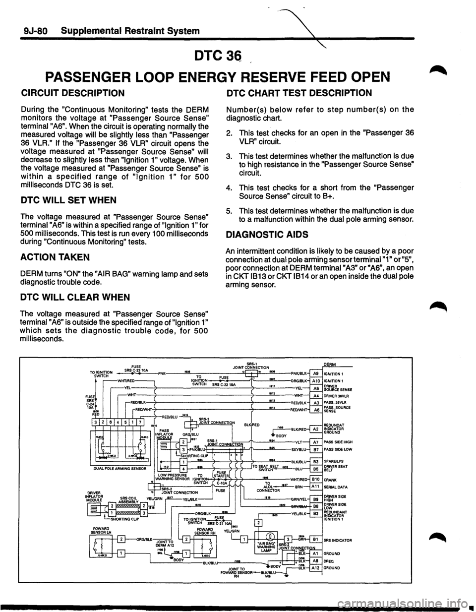
9J-80 Supplemental Restraint System
DTC36
PASSENGER LOOP ENERGY RESERVE FEED OPEN
CIRCUIT DESCRIPTION
During the "Continuous Monitoring" tests the DERM
monitors the voltage at
"Passenger Source Sense"
terminal "AS". When the circuit is operating normally the
measured voltage
will be slightly less than "Passenger
3S VLR." If the "Passenger 3S VLR" circuit opens the
voltage measured at
"Passenger Source Sense" will
decrease to slightly less than "Ignition 1" voltage. When
the voltage measured at
"Passenger Source Sense" is
within a specified range of "Ignition 1" for 500
milliseconds DTC 3S is set.
DTC WILL SET WHEN
The voltage measured at "Passenger Source Sense"
terminal "AS" is within a specified range of "Ignition 1" for
500 milliseconds. This test is run every 100 milliseconds
during "Continuous Monitoring" tests.
ACTION TAKEN
DERM turns "ON" the "AIR BAG" warning lamp and sets
diagnostic trouble code.
DTC WILL CLEAR WHEN
The voltage measured at "Passenger Source Sense"
terminal "AS" is outside the specified range of "Ignition 1"
which sets the diagnostic trouble code, for 500
milliseconds.
DTC CHART TEST DESCRIPTION
Number(s) below refer to step number(s) on the
diagnostic chart.
2. This test checks for an open in the "Passenger 3S
VLR" circuit.
3. This test determines whether the malfunction is due
to high resistance
in the "Passenger Source Sense"
circuit.
4. This test checks for a short from the
"Passenger
Source Sense"
circuit to B+.
5. This test determines whether the malfunction is due
to a malfunction within the dual pole arming sensor.
DIAGNOSTIC AIDS
An intermittent condition is likely to be caused by a poor
connection at dual pole arming sensor terminal
"1" or "5",
poor connection at DERM terminal "A3" or" AS", an open
in CKT 1813 or CKT 1814 or an open inside the dual pole
arming sensor.
SAS·l
JOINT CONNECTION ,.,. " IGNITION 1
DRIVER 38VLR PASS.38VLR PASS. SOURCE SENSE
PASS SIDE HIGH PASS SIDE LOW
SERIAL DATA
SRS INDICATOR
..
Page 1742 of 1928
9J-118 Supplemental Restraint System
attachments
- Driver seat and belt
- Passenger seat and belt
- Dual Pole Arming
Sensor
-Discriminating Sensors
-DERM
The sensor replacement policy specifies mandatory
replacement of the sensors, after crash involving
AIR
BAG deployment. If AIR BAG has not been deployd,
Replace the sensors
in the area of accident damage only.
The
"area of accident damage" is defined as that area of
the vehicle which is crushed, bent ,or damaged in other
ways. An example might be a front-end collision
in which
the forward portions of the vehicle have contacted
another vehicle, tree, guardrail,etc.
In this example,
1)
If AIR BAG has deployed, All Sensor should be
replaced.
2)
If AIR BAG has not deployed, replace the sensors
in the area of accident damage only.
sensor(s) on the radiator tie bar would require
replacement, since that portion of the vehicle was
damaged in the accident. The Dual Pole Arming Sensor
would not require mandatory replacement. Of course, if
the DERM sets a code and the diagnostic chart leads to
a faulty sensor that was not in the area of accident
damage, that sensor should also be replaced.Sensors
in
the area of accident damage should be replaced even if
those sensors do not appear to be damaged. Do not
attempt to determine whether a sensor is
OK-ALWAYS
replace it if it is in the area of accident damage.Aiso, if a
sensor is
in an area of accident damage,but the SRS has
NOT been deployed,replace the sensor.The sensor
bracket may be slightly bent,wiring may be
damaged, etc., and the sensor might not work properly
in
another collision. Again, do not attempt to determine
whether a sensor is
OK --ALWAYS replace it if it is in
the area of accident damage. Also,
inspect
SRS coil assembly wiring and steering
wheel for any signs of scorching, melting, or damage due
to excessive heat.
If the coil assembly wire or steering ~
wheel is damaged, replace them. The steering column
and wheel must be dimensionally checked to determine
if they are damaged. Refer to
in this Section 3 of this
manual.
Never use
SRS parts from another vehicle. This does not
include remanufactured parts purchased from an
authorized
ISUZU Dealer; they may be used for SRS
repairs.
Do not attempt to repair the forward discriminating
sensors ,the dual pole arming senor, the DERM, the
SRS
coil assembly, the inflator modules, the steering wheel, or
the steering column. Service of these items is
replacement only.
Verify replacement part numbers.
CAUTION: PROPER OPERATION OF THE
SENSORS AND SUPPLEMENTAL RESTRAINT
SYSTEM(SRS)REQUIRES THAT ANY REPAIRS TO
THE VEHICLE STRUCTURE RETURN IT TO ITS
ORIGINAL PRODUCTION CONFIGURATION.
II
Page 1784 of 1928
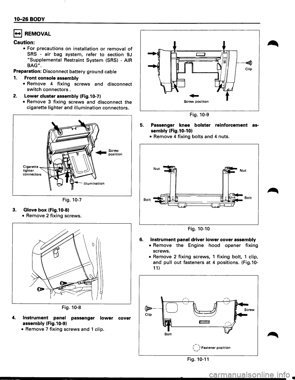
10-26 BODY
l••l REMOVAL
Caution:
• For precautions on installation or removal of
SRS -air bag system, refer to section 9J
"Supplemental Restraint System (SRS) -AIR
BAG".
Preparation: Disconnect battery ground cable
1. Front console assembly
•
Remove 4 fixing screws and disconnect
switch connectors .
2. Lower cluster assembly (Fig.10-7)
• Remove 3 fixing screws and disconnect the
cigarette
lighter and illumination connectors.
Cigarette ~c--!H---1\.+.....,. lighter connectors
Fig. 10-7
3. Glove box (Fig.10-8)
• Remove 2 fixing screws.
Fig.
10-8
4. Instrument panel passenger lower cover
assembly (Fig.10-9)
• Remove 7 fixing screws and 1 clip.
--41llj])
Clip
Screw posi iton
Fig. 10-9
5. Passenger knee bolster reinforcement as
sembly (Fig.10-10)
• Remove 4 fixing bolts and 4 nuts.
Bolt
Fig. 10-10
6. Instrument panel driver lower cover assembly
•
Remove the Engine hood opener fixing
screws.
• Remove 2 fixing screws, 1 fixing bolt, 1 clip,
and pull out fasteners at 4 positions. (Fig.10-
11)
@ate----
Clip
Bolt
{-J Fastener position '--
Fig. 10-11
..
Page 1787 of 1928
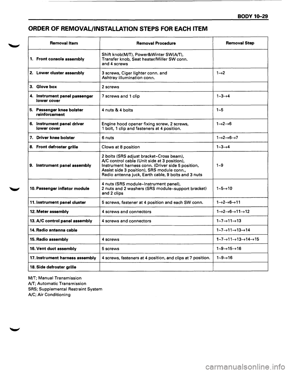
ORDER OF REMOVAL/INSTALLATION STEPS FOR EACH ITEM
Removal Item
1. Front console assembly
2. Lower cluster assembly
3. Glove box
4. Instrument panel passenger lower cover
5. Passenger knee bolster reinforcement
6. Instrument panel driver lower cover
7. Driver knee bolster
8. Front defroster grille
9. Instrument panel assembly
10. Passenger inflator module
11.1nstrument panel cluster
12. Meter assembly
13. A/C control panel assembly
14. Radio antenna cable
15. Radio assembly
16. Vent duct assembly
17 .Instrument harness assembly
18. Side defroster grille
MfT; Manual Transmission
A/T;
Automatic Transmission Removal
Procedure
Shift
knob(MfT), Power&Winter SW(A/T),
Transfer knob, Seat heater/Miller SW conn.
and 4 screws
3 screws, Ciger lighter conn. and
Ashtray illumination conn.
2 screws
7 screws and 1 clip
4 nuts & 4 bolts
Engine hood opener fixing screw, 2 screws, 1 bolt, 1 clip and fasteners at 4 position.
6 nuts
Claws at 8 position
2 bolts (SRS adjust bracket-Cross beam), A!C control cable (Unit side at 3 position), Instrument harness conn. (Driver side 5 position,
Assist side 3 position), SRS module conn.,
Radio antenna juck, Earth
cable, 9 bolts and 3 nuts
4 nuts (SRS module-Instrument panel), 2 nuts and 2 washers (SRS module-support bracket)
and 2 clips
5 screws, fastener at 4 position and each SW conn.
4 screws and connectors
4 screws and connectors
4 screws
5 screws
4 screws, fasteners at 4 position, and clips at 7 position.
SRS; Supplemental Restraint System
A!C; Air Conditioning
BODY 10-29
Removal Step
1~2
1~3~4
1~5
1~2~6
1~2~6~7
1-3~4
1~9
1-5~10
1~2~6~11
1~2~6~11~12
1-7~11~13
1-7~11~13~14
1~7~11~13~14~15
1-9~15~16
1-9~16