reset ISUZU TROOPER 1995 Workshop Manual
[x] Cancel search | Manufacturer: ISUZU, Model Year: 1995, Model line: TROOPER, Model: ISUZU TROOPER 1995Pages: 1928
Page 371 of 1928
REAR WHEEL ANTILOCK BRAKE SYSTEM 5A3-3
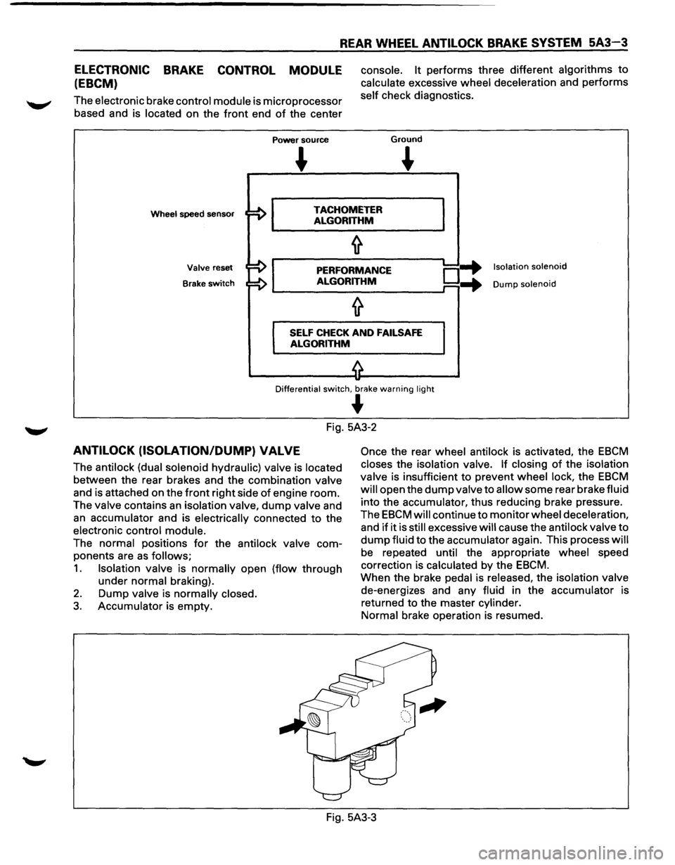
ELECTRONIC BRAKE CONTROL MODULE
(EBCM)
The electronic brake control module is microprocessor
based and is located on the
front end of the center
Power source
console. It performs three different algorithms to
calculate excessive wheel deceleration and performs
self check diagnostics.
Ground
~
Wheel speed sensor TACHOMETER
ALGORITHM
Valve reset
Brake
switch
PERFORMANCE
ALGORITHM o-+ ...
Isolation solenoid
Dump solenoid
SELF CHECK AND FAILSAFE
ALGORITHM
Differential switch, br<'!ke warning light
~
Fig. 5A3-2
ANTILOCK (ISOLATION/DUMP) VALVE
The antilock (dual solenoid hydraulic) valve is located
between the rear brakes and the combination valve
and is attached on the
front right side of engine room.
The valve contains
an isolation valve, dump valve and
an accumulator and is electrically connected to the
electronic control module.
The normal positions
for the antilock valve com
ponents are
as follows;
1. Isolation valve is normally open (flow through
under normal braking).
2. Dump valve is normally closed.
3. Accumulator is empty.
Once the rear wheel antilock is activated, the EBCM
closes the isolation valve. If closing of the isolation
valve is insufficient to prevent wheel lock, the
EBCM
will open the dump valve to allow some rear brake fluid
into the accumulator, thus reducing brake pressure.
The
EBCM will continue to monitor wheel deceleration,
and
if it is still excessive will cause the antilock valve to
dump fluid to the accumulator again. This process will
be repeated until the appropriate wheel speed
correction is calculated by the
EBCM.
When the brake pedal is released, the isolation valve
de-energizes and any fluid in the accumulator is
returned to the master cylinder.
Normal brake operation is resumed.
Fig. 5A3-3
Page 374 of 1928
5A3-6 REAR WHEEL ANTILOCK BRAKE SYSTEM
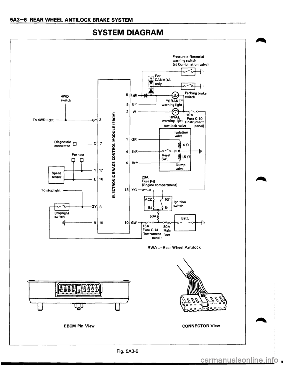
SYSTEM DIAGRAM
4WD
switch
To 4WD
light -----11~-----lGY 3
Diagnostic Of------0 7 connector
For test
1-----11---+--y 17 Speed
sensor 1-----lt-----L
16
To
stoplight -----,
Stoplight switch
•IJI-----B 15
EBCM Pin View
i
&l ~ IU _, :;) Q
~ _, 0 a: .... z
8 IU ~ c( a: liD (.) z 0 a: 1-(.) IU _, IU
Pressure differential warning switch
(at Combination valve)
r-----+-<1 ~+II•
I•
6 LgB Parking brake _.-MI ____ ___,I'\.JI.Jr-, switch
5
BP -----'
2 w ------------~~._~
GR
4 BrR
9 BrY
20A Fuse F-9
RWAL 10
A •
1• h Fuse C-10
warnmg IQ t (Instrument
Antilock valve panel)
Isolation
valve
~ 4il .J o--1> ~
Reset ~1.5il
I
sw.
Dump valve
(Engine compartment)
13 YG -
82 81 switch
50 A
Batt.
10 GW + ,,
15A BOA Fuse C-14 Main (Instrument fuse panel)
RWAL=Rear Wheel Antilock
CONNECTOR View
Fig. 5A3-6
•
Page 375 of 1928
REAR WHEEL ANTILOCK BRAKE SYSTEM 5A3-7
REAR WHEEL ANTILOCK (RWAL) SYSTEM DIAGNOSTICS
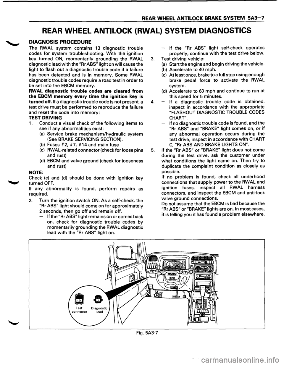
DIAGNOSIS PROCEDURE
The RWAL system contains 13 diagnostic trouble
codes
for system troubleshooting. With the ignition
key turned
ON, momentarily grounding the RWAL
diagnostic lead
with the "Rr ABS" light on will cause the
light
to flash out a diagnostic trouble code if a failure
has been detected and is in memory.
Some RWAL
diagnostic trouble codes require a road test in order
to
be set into the EBCM memory.
RWAL diagnostic trouble codes are cleared from
the
EBCM memory every time the ignition key is
turned off. If a diagnostic trouble code is not present, a
test drive
must be performed to reproduce the failure
and reset the code into
memory:
TEST DRIVING
1. Conduct a visual check of the following items to
see if any abnormalities exist:
(a) Service brake mechanism/hydraulic system
(See BRAKE SERVICING SECTION).
(b) Fuses #2, #7, #14 and main fuse
(c) RWAL-related connector (check for loose pins
and rust)
(d) EBCM and valve ground (check for looseness
and rust)
NOTE:
Check
(c) and (d) should be done with ignition key
turned
OFF.
If any abnormality is found, perform repairs as
required.
2. Turn the ignition switch ON. As a self-check, the
"Rr ABS" light should come on for approximately
2 seconds, then go
off and remain off.
If the "Rr ABS" light remains on or comes back
on, check
for diagnostic trouble codes by
momentarily grounding the RWAL diagnostic
lead
with the "Rr ABS" light on. -
If the "Rr
ABS" light self-check operates
properly, continue
with the test drive below.
3. Test driving vehicle:
(a) Start the engine and begin driving the vehicle.
(b) Accelerate to 40 mph.
(c) At least once, brake to a full stop using enough
brake pedal force
to activate the RWAL
system.
(d) Accelerate to 60 mph and continue to run at
this speed
for 5 minutes.
4. If a diagnostic trouble code is obtained.
inspect in accordance
with the appropriate
"FLASHOUT DIAGNOSTIC TROUBLE CODES
CHART".
If
no diagnostic trouble code is found, and the
"Rr ABS" and "BRAKE" light comes on, or if
any abnormal operation occurs during the
test drive, inspect in accordance
with CHART
C, "Rr ABS AND BRAKE LIGHTS ON".
5. If the "Rr ABS" or "BRAKE" light does not come
during the test drive, ask the customer under
what conditions the light came on. Then try to
duplicate the complaint condition
as closely as
possible.
If no problem is found, check all underhood
connections that supply power
to the RWAL and
ignition fuses, inspect
all RWAL harness
connectors, and inspect the
EBCM and anti-lock
valve ground connections.
Do not assume that the
EBCM is bad because the
"Rr ABS" or "BRAKE" lights are on. In most cases,
it is telling you it has found a problem elsewhere.
Fig. 5A3-7
Page 388 of 1928
5A3-20 REAR WHEEL ANTILOCK BRAKE SYSTEM
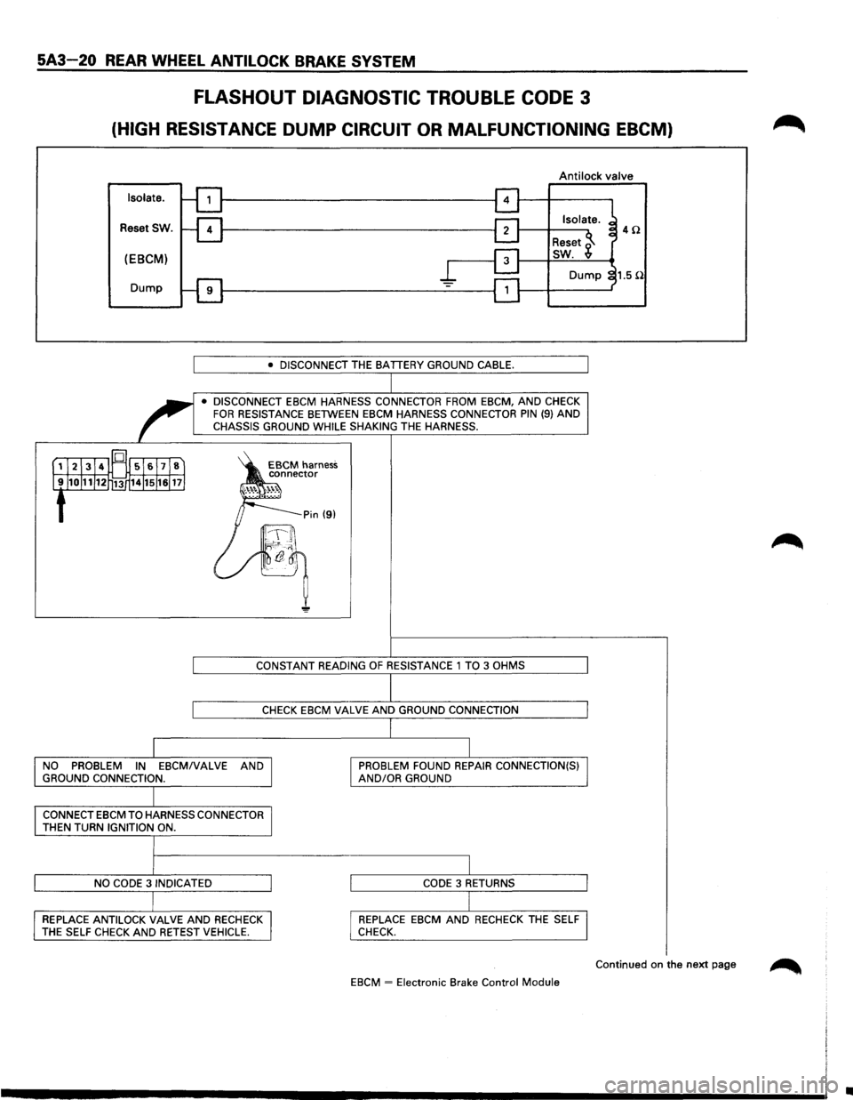
FLASHOUT DIAGNOSTIC TROUBLE CODE 3
(HIGH RESISTANCE DUMP CIRCUIT OR MALFUNCTIONING EBCM)
Anti lock valve
Isolate.
Reset SW.
(EBCM)
Dump
• DISCONNECT THE BATTERY GROUND CABLE.
• DISCONNECT EBCM HARNESS CONNECTOR FROM EBCM,
AND CHECK FOR RESISTANCE BETWEEN EBCM HARNESS CONNECTOR PIN (9) AND CHASSIS GROUND WHILE SHAKING THE HARNESS.
CONSTANT READING
OF RESISTANCE 1 TO 3 OHMS
CHECK EBCM
VALVE AND GROUND CONNECTION
NO
PROBLEM IN EBCMIVALVE AND
GROUND CONNECTION.
CONNECT EBCM TO HARNESS CONNECTOR
THEN TURN IGNITION ON.
NO CODE 31NDICATED
REPLACE ANTILOCK
VALVE AND RECHECK THE SELF CHECK AND RETEST VEHICLE.
PROBLEM FOUND REPAIR CONNECTION(S) AND/OR GROUND
CODE 3 RETURNS
REPLACE EBCM
AND RECHECK THE SELF
CHECK.
EBCM
~ Electronic Brake Control Module
4Q
1.5 !l
Continued on the next page
•
Page 390 of 1928
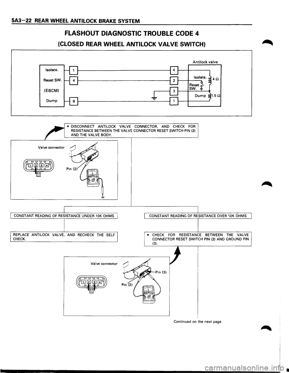
5A3-22 REAR WHEEL ANTILOCK BRAKE SYSTEM
FLASHOUT DIAGNOSTIC TROUBLE CODE 4
(CLOSED REAR WHEEL ANTILOCK VALVE SWITCH)
Isolate.
Reset SW.
(EBCM)
Dump
Valve connector
Anti lock valve
• DISCONNECT ANTILOCK VALVE CONNECTOR, AND CHECK FOR RESISTANCE BETWEEN THE VALVE CONNECTOR RESET SWITCH PIN {2) AND THE VALVE BODY.
4Q
CONSTANT READING OF RESISTANCE UNDER 10K OHMS
CONSTANT READING OF RESISTANCE OVER 10K OHMS
REPLACE ANTILOCK VALVE, AND RECHECK THE SELF CHECK.
Valve connector
• CHECK FOR RESISTANCE BETWEEN THE VALVE CONNECTOR RESET SWITCH PIN {2) AND GROUND PIN (3).
Continued on the next page
•
Page 391 of 1928
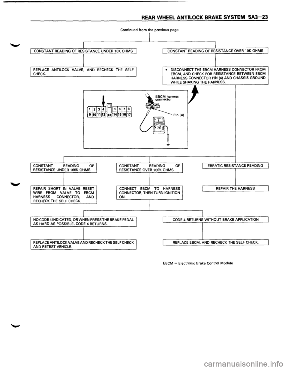
REAR WHEEL ANTILOCK BRAKE SYSTEM 5A3-23
Continued from the previous page
CONSTANT READING OF RESISTANCE UNDER 10K OHMS
REPLACE ANTILOCK VALVE, AND RECHECK THE SELF
CHECK. CONSTANT
READING
OF RESISTANCE OVER 10K OHMS
• DISCONNECT
THE EBCM HARNESS CONNECTOR FROM
EBCM, AND CHECK FOR RESISTANCE BETWEEN EBCM HARNESS CONNECTOR PIN (4) AND CHASSIS GROUND WHILE SHAKING THE HARNESS.
CONSTANT READING
OF CONSTANT READING OF ERRATIC RESISTANCE READING RESISTANCE UNDER 100K OHMS
REPAIR SHORT IN VALVE RESET
WIRE FROM VALVE TO EBCM HARNESS CONNECTOR, AND
RECHECK THE SELF CHECK. RESISTANCE
OVER 100K OHMS
CONNECT
EBCM TO HARNESS
CONNECTOR, THEN TURN IGNITION
ON. REPAIR THE HARNESS
NO CODE 41NDICATED,
OR WHEN PRESS THE BRAKE PEDAL AS HARD AS POSSIBLE, CODE 4 RETURNS. CODE 4 RETURNS WITHOUT BRAKE APPLICATION
REPLACE ANTI LOCK VALVE AND RECHECK THE SELF CHECK AND RETEST VEHICLE. REPLACE EBCM, AND RECHECK THE SELF CHECK.
EBCM
-Electronic Brake Control Module
Page 395 of 1928
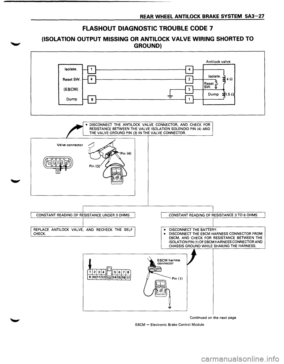
REAR WHEEL ANTILOCK BRAKE SYSTEM 5A3-27
FLASHOUT DIAGNOSTIC TROUBLE CODE 7
(ISOLATION OUTPUT MISSING OR ANTI LOCK VALVE WIRING SHORTED TO
GROUND)
Anti lock valve
Isolate.
ResetSW. 40
(EBCM)
Dump
• DISCONNECT THE ANTILOCK VALVE CONNECTOR, AND CHECK FOR RESISTANCE BETWEEN THE VALVE ISOLATION SOLENOID PIN (4) AND
THE VALVE GROUND PIN (3) IN THE VALVE CONNECTOR.
Valve
connector
CONSTANT READING OF RESISTANCE UNDER 3 OHMS
REPLACE ANTILOCK VALVE, AND RECHECK THE SELF CHECK.
CONSTANT READING OF RESISTANCE 3 TO 6 OHMS
• DISCONNECT
THE BATTERY. • DISCONNECT THE EBCM HARNESS CONNECTOR FROM EBCM, AND CHECK FOR RESISTANCE BETWEEN THE ISOLATION PIN (1) OF EBCM HARNESS CONNECTOR AND CHASSIS GROUND WHILE SHAKING THE HARNESS.
Continued on the next page
EBCM
= Electronic Brake Control Module
Page 397 of 1928
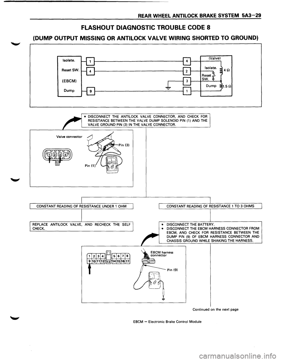
REAR WHEEL ANTILOCK BRAKE SYSTEM 5A3-29
FLASHOUT DIAGNOSTIC TROUBLE CODE 8
(DUMP OUTPUT MISSING OR ANTILOCK VALVE WIRING SHORTED TO GROUND)
Isolate.
Reset SW.
(EBCM)
Dump
• DISCONNECT THE ANTILOCK VALVE CONNECTOR, AND CHECK FOR RESISTANCE BETWEEN THE VALVE DUMP SOLENOID PIN (1) AND THE VALVE GROUND PIN (3) IN THE VALVE CONNECTOR.
Valve
connector
CONSTANT READING OF RESISTANCE UNDER 1 OHM
REPLACE ANTILOCK VALVE, AND RECHECK THE SELF CHECK.
CONSTANT READING OF RESISTANCE 1 TO 3 OHMS
• DISCONNECT
THE BATIERY.
• DISCONNECT THE EBCM HARNESS CONNECTOR FROM EBCM, AND CHECK FOR RESISTANCE BETWEEN THE
DUMP PIN (9) OF EBCM HARNESS CONNECTOR AND CHASSIS GROUND WHILE SHAKING THE HARNESS.
Pin (9)
Continued on the
next page
EBCM
-Electronic Brake Control Module
Page 512 of 1928
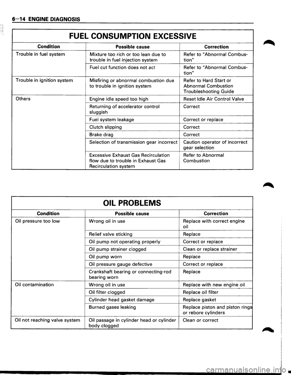
6-14 ENGINE DIAGNOSIS
1;:-
FUEL CONSUMPTION EXCESSIVE
Condition
Possible cause Correction
Trouble in fuel system
Mixture too rich or too lean due to Refer to "Abnormal Combus-
trouble in fuel injection system tion"
Fuel cut function does not act Refer to "Abnormal Combus-
tion"
Trouble in ignition system
Misfiring or abnormal combustion due Refer to Hard Start or
to trouble in ignition system Abnormal Combustion
Troubleshooting Guide
Others Engine idle speed too high Reset Idle Air Control Valve
Returning
of accelerator control Correct
sluggish
Fuel system leakage
Correct or replace
Clutch slipping Correct
Brake drag Correct
Selection of transmission gear incorrect Caution operator of incorrect
gear selection
Excessive Exhaust
Gas Recirculation Refer to Abnormal
flow due to trouble in Exhaust Gas Combustion
Recirculation system
OIL PROBLEMS
Condition
Possible cause Correction
Oil pressure too low Wrong oil in use Replace with correct
engine
oil
Relief valve sticking Replace
Oil pump not operating
properly Correct or replace
Oil pump strainer clogged Clean or replace strainer
Oil pump worn Replace
Oil pressure gauge defective Correct or replace
Crankshaft bearing or connecting-rod Replace
bearing
worn
Oil contamination Wrong oil in use Replace with new engine
oil
Oil filter clogged Replace oil filter
Cylinder head gasket damage Replace
gasket
Burned gases leaking Replace piston and piston rings
or rebore cylinders
Oil not reaching valve system Oil passage in cylinder head or cylinder Clean or correct
body clogged
•
Page 752 of 1928
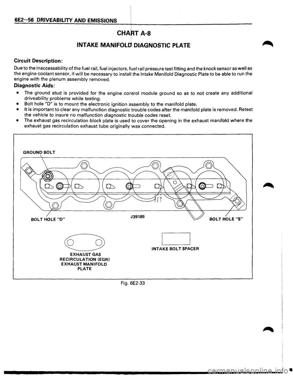
Circuit Description:
Due to the inaccessability of the fuel rail, fuel injectors, fuel rail pressure test fitting and the knock sensor as well as
the engine coolant sensor, it will be necessary to install the Intake Manifold Diagnostic Plate to be able to run the
engine with the
plenum assembly removed.
Diagnostic Aids:
• The ground stud is provided for the engine control module ground so as to not create any additional
driveability problems while
testing.
• Bolt hole "D" is to mount the electronic ignition assembly to the manifold plate.
• It
is important to clear any malfunction diagnostic trouble codes after the manifold plate is removed. Retest
the
vehicle to insure no malfunction diagnostic trouble codes reset.
• The exhaust gas recirculation block plate is used to cover the opening in the exhaust manifold where the
exhaust gas
recirculation exhaust tube originally was connected.
GROUND BOLT
~
EXHAUST GAS
RECIRCULATION
(EGR)
EXHAUST MANIFOLD PLATE
INTAKE BOLT SPACER
Fig. 6E2-33
•