octane ISUZU TROOPER 1995 Workshop Manual
[x] Cancel search | Manufacturer: ISUZU, Model Year: 1995, Model line: TROOPER, Model: ISUZU TROOPER 1995Pages: 1928
Page 506 of 1928
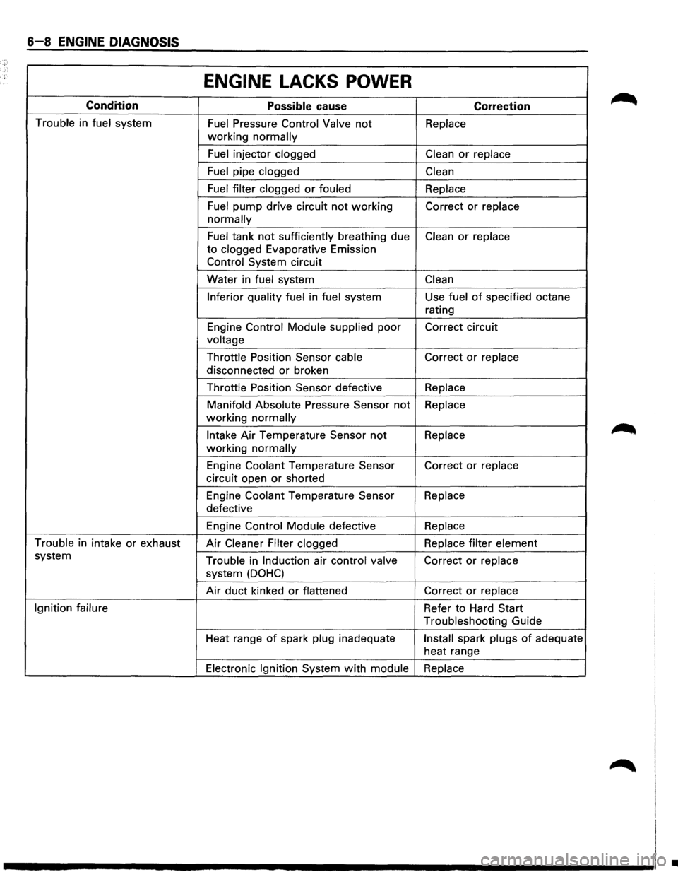
6-8 ENGINE DIAGNOSIS
ENGINE LACKS POWER
Condition
Possible cause Correction
Trouble in fuel system Fuel Pressure Control Valve not Replace
working normally
Fuel
injector clogged Clean or replace
Fuel
pipe clogged Clean
Fuel filter clogged
or fouled Replace
Fuel
pump drive circuit not working Correct or replace
normally
Fuel tank not sufficiently breathing due Clean or replace
to clogged Evaporative Emission
Control System circuit
Water in
fuel system Clean
Inferior quality fuel
in fuel system Use fuel of specified octane
rating
Engine
Control Module supplied poor Correct circuit
voltage
Throttle
Position Sensor cable Correct or replace
disconnected or broken
Throttle Position Sensor defective Replace
Manifold Absolute
Pressure Sensor not Replace
working normally
Intake Air Temperature Sensor not Replace
working normally
Engine Coolant Temperature Sensor Correct or replace
circuit open or shorted
Engine
Coolant Temperature Sensor Replace
defective
Engine
Control Module defective Replace
Trouble
in intake or exhaust Air Cleaner Filter clogged Replace filter element
system Trouble in Induction air control valve Correct or replace
system (DOHC)
Air duct kinked or flattened Correct or replace
Ignition failure
Refer to Hard Start
Troubleshooting Guide
Heat range
of spark plug inadequate Install spark plugs of adequate
heat range
Electronic Ignition System with module Replace
•
Page 509 of 1928
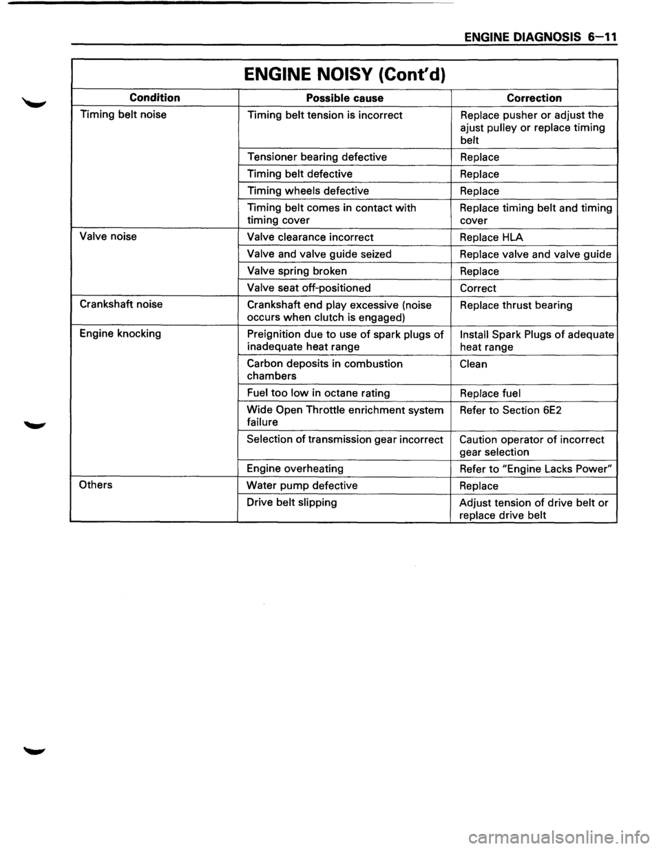
ENGINE DIAGNOSIS 6-11
ENGINE NOISY (Cont'd)
Condition Possible cause Correction
Timing belt noise
Timing belt tension is incorrect Replace pusher or adjust the
ajust
pulley or replace timing
belt
Tensioner bearing defective Replace
Timing belt defective Replace
Timing wheels defective Replace
Timing belt comes in contact with Replace timing belt and timing
timing cover
cover
Valve noise Valve clearance incorrect Replace HLA
Valve and valve guide seized Replace valve and valve guide
Valve spring broken Replace
Valve
seat off-positioned
Correct
Crankshaft noise
Crankshaft end
play excessive (noise Replace thrust bearing
occurs
when clutch is engaged)
Engine knocking
Preignition due
to use of spark plugs of Install Spark Plugs of adequate
inadequate heat range
heat range
Carbon deposits in combustion
Clean
chambers
Fuel too low in octane rating Replace fuel
Wide Open Throttle enrichment system
Refer to Section 6E2
failure
Selection
of transmission gear incorrect Caution operator of incorrect
gear
selection
Engine overheating
Refer to "Engine Lacks Power"
Others Water
pump defective Replace
Drive belt slipping Adjust tension of drive belt or
replace drive belt
Page 788 of 1928
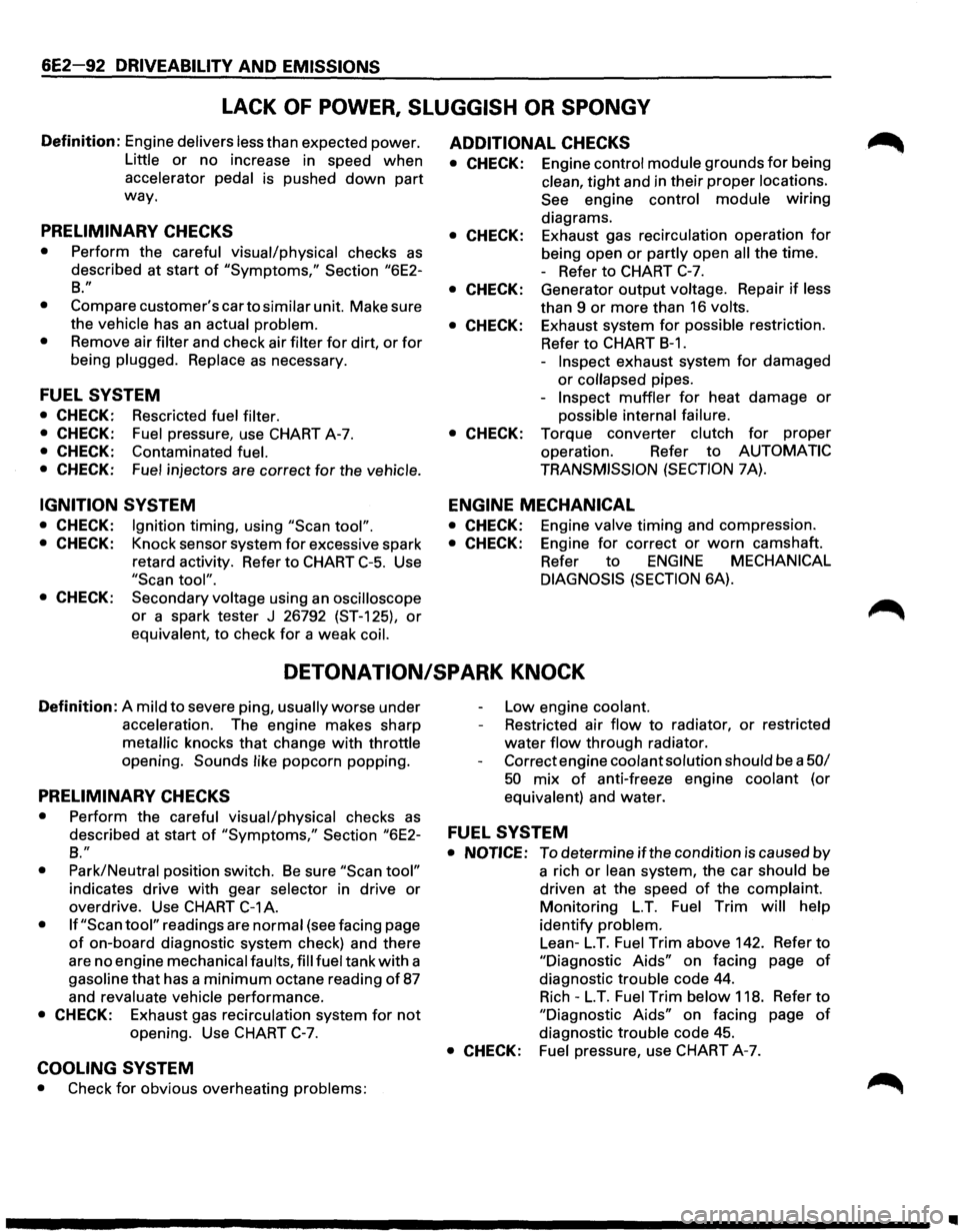
6E2-92 DRIVEABILITY AND EMISSIONS
LACK OF POWER, SLUGGISH OR SPONGY
Definition: Engine delivers less than expected power.
Little or no increase in speed when
accelerator
pedal is pushed down part
way.
PRELIMINARY CHECKS
• Perform the careful visual/physical checks as
described at start of "Symptoms," Section "6E2-
B."
•
Compare customer's car to similar unit. Make sure
the
vehicle has an actual problem.
• Remove air filter and check air filter for dirt, or for
being plugged. Replace as necessary.
FUEL SYSTEM
• CHECK: Rescricted fuel filter.
• CHECK: Fuel pressure, use CHART A-7.
• CHECK: Contaminated fuel.
• CHECK: Fuel injectors are correct for the vehicle.
IGNITION SYSTEM
• CHECK: Ignition timing, using "Scan tool".
• CHECK: Knock sensor system for excessive spark
retard activity. Refer to CHART
C-5. Use
"Scan tool".
• CHECK: Secondary voltage using an oscilloscope
or a spark tester J 26792 (ST-125), or
equivalent, to check for a weak coil.
ADDITIONAL CHECKS
• CHECK: Engine control module grounds for being
clean,
tight and in their proper locations.
See engine control module wiring
diagrams.
• CHECK: Exhaust gas recirculation operation for
being open or partly open all the time.
- Refer to CHART
C-7.
• CHECK: Generator output voltage. Repair if less
than 9
or more than 16 volts.
• CHECK: Exhaust system for possible restriction.
Refer
to CHART B-1.
-Inspect exhaust system for damaged
or collapsed pipes.
-
Inspect muffler for heat damage or
possible internal failure.
• CHECK: Torque converter clutch for proper
operation. Refer
to AUTOMATIC
TRANSMISSION
(SECTION 7A).
ENGINE MECHANICAL
• CHECK: Engine valve timing and compression.
• CHECK: Engine for correct or worn camshaft.
Refer
to ENGINE MECHANICAL
DIAGNOSIS
(SECTION 6A).
DETONATION/SPARK KNOCK
Definition: A mild to severe ping, usually worse under
acceleration. The engine makes sharp
metallic knocks that change with throttle
opening.
Sounds like popcorn popping.
PRELIMINARY CHECKS
• Perform the careful visual/physical checks as
Low engine coolant.
Restricted air
flow to radiator, or restricted
water flow through radiator.
Correct engine
coolant solution should be a 50/
50 mix of anti-freeze engine coolant (or
equivalent) and water.
described at start
of "Symptoms," Section "6E2-FUEL SYSTEM
B."
•
Park/Neutral position switch. Be sure "Scan tool"
indicates drive with gear selector in drive or
overdrive. Use
CHART C-1A.
• If "Scan tool" readings are normal (see facing page
of on-board diagnostic system check) and there
are no engine mechanical faults,
fill fuel tank with a
gasoline
that has a minimum octane reading of 87
and revaluate vehicle performance.
• CHECK: Exhaust gas recirculation system for not
opening. Use CHART C-7.
COOLING SYSTEM
• Check for obvious overheating problems:
• NOTICE: To determine if the condition is caused by
a rich
or lean system, the car should be
driven at the speed
of the complaint.
Monitoring
LT. Fuel Trim will help
identify problem.
Lean-
LT. Fuel Trim above 142. Refer to
"Diagnostic Aids" on facing page of
diagnostic trouble code 44.
Rich-LT. Fuel Trim below 118. Refer to
"Diagnostic Aids" on facing page of
diagnostic trouble code 45.
• CHECK: Fuel pressure, use CHART A-7.
..
Page 842 of 1928
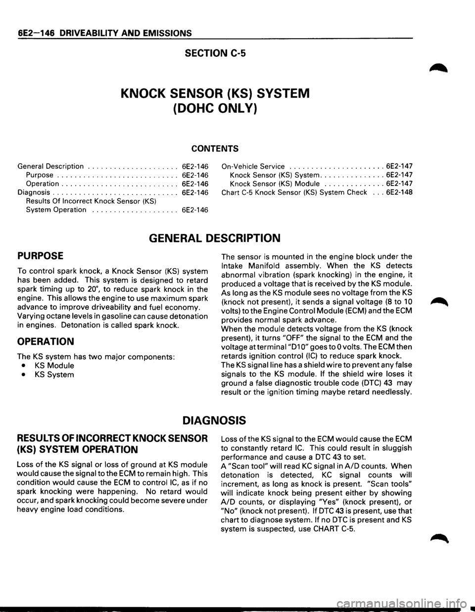
6E2-146 DRIVEABILITY AND EMISSIONS
SECTION C-5
KNOCK SENSOR (KS) SYSTEM
(DOHC ONLY)
CONTENTS
General Description ..................... 6E2-146 On-Vehicle Service ...................... 6E2-147
Purpose
............................ 6E2-146 Knock Sensor (KS) System ............... 6E2-147
Operation . . . . . . . . . . . . . . . . . . . . . . . . . . . 6E2-146 Knock
Sensor
(KS) Module .............. 6E2-147
Diagnosis
............................. 6E2-146 Chart C-5 Knock Sensor (KS) System Check ... 6E2-148
Results
Of Incorrect Knock Sensor (KS)
System Operation .................... 6E2-146
GENERAL DESCRIPTION
PURPOSE
To control spark knock, a Knock Sensor (KS) system
has been added. This system is designed to retard
spark timing up to
20·, to reduce spark knock in the
engine. This
allows the engine to use maximum spark
advance to improve driveability and fuel economy.
Varying octane
levels in gasoline can cause detonation
in engines. Detonation
is called spark knock.
OPERATION
The KS system has two major components:
• KS Module
• KS System
The sensor is mounted in the engine block under the
Intake Manifold assembly. When the KS detects
abnormal vibration (spark knocking) in the engine,
it
produced a voltage that is received by the KS module.
As long
as the KS module sees no voltage from the KS
(knock not present), it sends a signal voltage (8 to 10
volts) to the Engine Control Module (ECM) and the ECM
provides normal spark advance.
When the module detects voltage
from the KS (knock
present),
it turns "OFF" the signal to the ECM and the
voltage at terminal
"D1 0" goes toO volts. The ECM then
retards ignition control
(IC) to reduce spark knock.
The
KS signal line has a shield wire to prevent any false
signals to the
KS module. If the shield wire loses it
ground a false diagnostic trouble code (DTC) 43 may
result
or the ignition timing maybe retard needlessly.
DIAGNOSIS
RESULTS OF INCORRECT KNOCK SENSOR
(KS) SYSTEM OPERATION
Loss of the KS signal or loss of ground at KS module
would cause the signal to the ECM to remain high. This
condition
would cause the ECM to control IC, as if no
spark knocking were happening. No retard
would
occur, and spark knocking could become severe under
heavy engine load conditions. Loss
of the KS signal
to the ECM would cause the ECM
to constantly retard IC. This could result in sluggish
performance and cause a
DTC 43 to set.
A
"Scan tool" will read KC signal in A/D counts. When
detonation is detected,
KC signal counts will
increment, as long as knock is present. "Scan tools"
will
indicate knock being present either by showing
AID counts, or displaying "Yes" (knock present), or
"No" (knock not present). If DTC 43 is present, use that
chart to diagnose system. If no DTC is present and KS
system is suspected, use CHART C-5.
•