heating ISUZU TROOPER 1995 Workshop Manual
[x] Cancel search | Manufacturer: ISUZU, Model Year: 1995, Model line: TROOPER, Model: ISUZU TROOPER 1995Pages: 1928
Page 3 of 1928
•:1
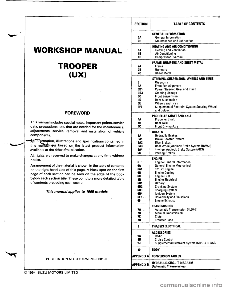
SECTION TABLE OF CONTENTS
. GENERAL INFORMATION OA General Information OB Maintenance and Lubrication
WORKSHOP MANUAL
HEATING AND AIR CONDITIONING 1A Heating and Ventilation
1B Air Conditioning 1D Compressor Overhaul
TROOPER
FRAME, BUMPERS AND SHEET METAL
2A Frame 2B Bumpers
(UX) 2C Sheet Metal
STEERING, SUSPENSION, WHEELS AND TIRES
3 Diagnosis 3A Front End Alignment 3B1 Power Steering Gear and Pump 3B3 Steering Linkage 3C Front Suspension 3D Rear Suspension 3E Wheels and Tires 3F4 Supplemental Restraint System Steering Wheel
FOREWORD and Column
PROPELLER SHAFT AND AXLE 4A Propeller Shaft This manual includes special notes, important points, service 4B Rear Axle
data, precautions, etc. that are needed for the maintenance, 4C Front Driving Axle
adjustments, service, removal and installation of vehicle BRAKES components. 5A Hydraulic Brakes
·~ m rmation, illustrations and specifications contained in 5A1 Brake Booster System
.. _,. 5A2 Disc Brakes ~ this ma. ~-based D.fl the latest product information 5A3 Rear Wheei_Antilock Brake System (RWAL)
available at the tirrHHrl·publication. 5A4 4-wheel Antilock Brake System (ABS)
5C Parking Brakes All rights are reserved to make changes at any time without ENGINE notice. 6· Engine General Information Arrangement of the material is shown in the table of contents &A General Engine Mechanical
on the right-hand side of this page. A black spot on the first 6A1 3.2L VB Engine
page of each section can be seen on the edge of the book &B Engine Cooling
6C Engine Fuel below each section title. These point to a more detailed table &D Engine Electrical of contents preceding each section. 6D1 Battery 6D2 Cranking System
This manual applies to 1995 models. 6D3 Charging System 6D4-Ignition System 6E2. Driveability and Emissions 6F Engine Exhaust
TRANSMISSION 7A-Automatic Transmission (4L30·E) 7B Manual Transmission 7C Clutch 7D Transfer Case
8 CHASSIS ELECTRICAL
ACCESSORIES 9A Radio 9B Cruise Control 9J Supplemental Restraint System (SRS)-AIR BAG
10 BODY
APPENDIX A CONVERSION TABLES PUBLICATION NO. UXOO-WSM-L0001-00
APPENDIXB HYDRAULIC CIRCUIT DIAGRAM (Automatic Transmission)
© 1994 ISUZU MOTORS LIMITED
Page 21 of 1928
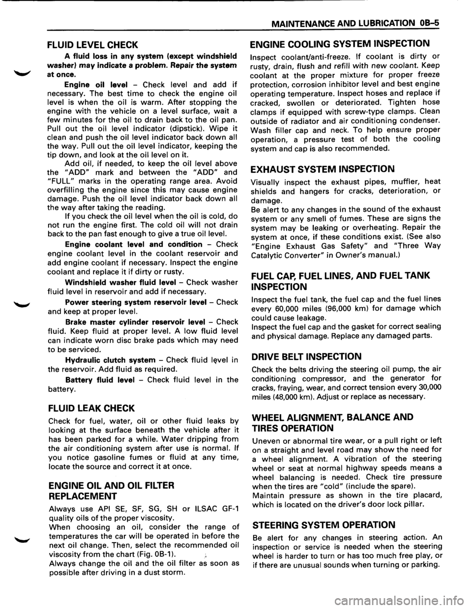
FLUID LEVEL CHECK
A fluid loss in any system (except windshield
washer) may indicate a problem. Repair the system
at once.
Engine
oil level -Check level and add if
necessary. The best time to check the engine oil
level is
when the oil is warm. After stopping the
engine with the vehicle on a level surface, wait a
few minutes for the oil to drain back to the oil pan.
Pull
out the oil level indicator (dipstick). Wipe it
clean and push the oil level indicator back down all
the
way. Pull out the oil level indicator, keeping the
tip down, and look at the oil level on it.
Add oil, if needed, to keep the oil level above
the
"ADD" mark and between the "ADD" and
"FULL" marks in the operating range area. Avoid
overfilling the engine since this may cause engine
damage. Push
the oil level indicator back down all
the
way after taking the reading.
If you check the oil level when the oil is cold, do
not run the engine first. The cold oil will not drain
back
to the pan fast enough to give a true oil level.
Engine coolant level and condition -Check
engine coolant level in the coolant reservoir and
add engine
coolant if necessary. Inspect the engine
coolant and replace it if dirty or rusty.
Windshield washer fluid level -Check washer
fluid level in reservoir and add if necessary.
Power steering system reservoir level-Check
and keep at
proper level.
Brake master cylinder reservoir level -Check
fluid. Keep fluid at proper level. A low fluid level
can indicate
worn disc brake pads which may need
to be serviced.
Hydraulic clutch system -Check fluid l~vel in
the reservoir.
Add fluid as required.
Battery fluid level -Check fluid level in the
battery.
FLUID LEAK CHECK
Check for fuel, water, oil or other fluid leaks by
looking at the surface beneath the vehicle after it
has been parked for a while. Water dripping from
the air conditioning system after use is normal. If
you notice gasoline fumes or fluid at any time,
locate the source and correct it at once.
ENGINE OIL AND OIL FILTER
REPLACEMENT
Always use API SE, SF, SG, SH or ILSAC GF-1
quality oils of the proper viscosity.
When choosing an oil, consider the range of
temperatures the car will be operated in before the
next oil change. Then, select the recommended oil
viscosity
from the chart (Fig. OB-1).
Always change the oil and the oil filter as soon as
possible after driving in a dust storm.
MAINTENANCE AND LUBRICATION OB-5
ENGINE COOLING SYSTEM INSPECTION
Inspect coolant/anti-freeze. If coolant is dirty or
rusty, drain, flush and refill with new coolant. Keep
coolant at the proper mixture for proper freeze
protection,
corrosion inhibitor level and best engine
operating temperature.
Inspect hoses and replace if
cracked, swollen or deteriorated. Tighten hose
clamps if equipped with screw-type clamps. Clean
outside of radiator and air conditioning condenser.
Wash
filler cap and neck. To help ensure proper
operation, a pressure test of both the cooling
system and cap is also recommended.
EXHAUST SYSTEM INSPECTION
Visually inspect the exhaust pipes, muffler, heat
shields and hangers
for cracks, deterioration, or
damage.
Be alert to any changes in the sound of the exhaust
system
or any smell of fumes. These are signs the
system may be leaking or overheating. Repair the
system at once,
if these conditions exist. (See also
"Engine Exhaust Gas Safety" and "Three Way
Catalytic Converter" in Owner's manual.)
FUEL CAP, FUEL LINES, AND FUEL TANK
INSPECTION
Inspect the fuel tank, the fuel cap and the fuel lines
every
60,000 miles (96,000 km) for damage which
could cause leakage.
Inspect the fuel cap and the gasket for correct sealing
and physical damage. Replace any damaged parts.
DRIVE BELT INSPECTION
Check the belts driving the steering oil pump, the air
conditioning compressor, and the generator
for
cracks, fraying, wear, and correct tension every 30,000
miles (48,000 km). Adjust or replace as necessary.
WHEEL ALIGNMENT, BALANCE AND
TIRES OPERATION
Uneven or abnormal tire wear, or a pull right or left
on a straight and level road may show the need for
a wheel alignment. A vibration of the steering
wheel or seat at normal highway speeds means a
wheel balancing is needed. Check tire pressure
when the tires are "cold" (include the spare).
Maintain pressure as shown in the tire placard,
which is located on the driver's door lock pillar.
STEERING SYSTEM OPERATION
Be alert for any changes in steering action. An
inspection
or service is needed when the steering
wheel is harder
to turn or has too much free play, or
if there are unusual sounds when turning or parking.
Page 31 of 1928
HEATING AND VENTILATION 1A-1
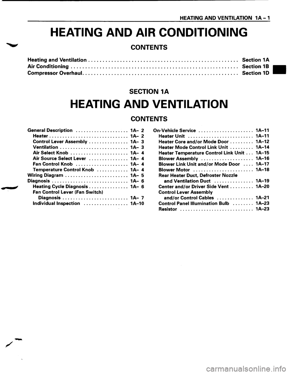
HEATING AND AIR CONDITIONING
CONTENTS
Heating and Ventilation .................................................... Section 1A
Air Conditioning . . . . . . . . . . . . . . . . . . . . . . . . . . . . . . . . . . . . . . . . . . . . . . . . . . . . . . . . . . Section 1 B
Compressor Overhaul. . .
. . . . . . . . . . . . . . . . . . . . . . . . . . . . . . . . . . . . . . . . . . . . . . . . . . . Section 1 D
SECTION 1A
HEATING AND VENTILATION
CONTENTS
General Description .................... 1A-2 On-Vehicle Service ..................... 1A-11
Heater . . . . . . . . . . . . . . . . . . . . . . . . . . . . . . 1
A-2 Heater Unit . . . . . . . . . . . . . . . . . . . . . . . . . 1A-11
Control Lever Assembly . . . . . . . . . . . . . . . 1 A-3 Heater Core and/or Mode Door ......... 1A-12
Ventilation .......................... 1A-3 Heater Mode Control Link Unit ......... 1A-14
Air Select Knob . . . . . . . . . . . . . . . . . . . . . . 1 A-4 Heater Temperature Control Link Unit ... 1A-15
Air Source Select Lever ............... 1A-4 Blower Assembly .................... 1A-16
Fan Control Knob .................... 1A-4 Blower Link Unit and/or Mode Door . . . . 1A-17
Temperature Control Knob ............ 1A-4 Blower Motor ....................... 1A-18
Wiring Diagram . . . . . . . . . . . . . . . . . . . . . . . . 1A-5
Rear Heater Duct, Defroster Nozzle
Diagnosis ............................. 1A-6 and Ventilation Duct ............... 1A-19
.. # Heating Cycle Diagnosis ............... 1A-6 Center and/or Driver Side Vent ......... 1A-20
Fan Control Lever (Fan Switch) Control Lever Assembly
Diagnosis . . . . . . . . . . . . . . . . . . . . . . . . . 1 A-7 and/or Control Cables .............. 1A-21
Individual Inspection ................. 1A-10 Control Panel Illumination Bulb ........ 1A-23
Resistor ............................ 1A-23
Page 32 of 1928
1A-2 HEATING AND VENTILATION
GENERAL DESCRIPTION
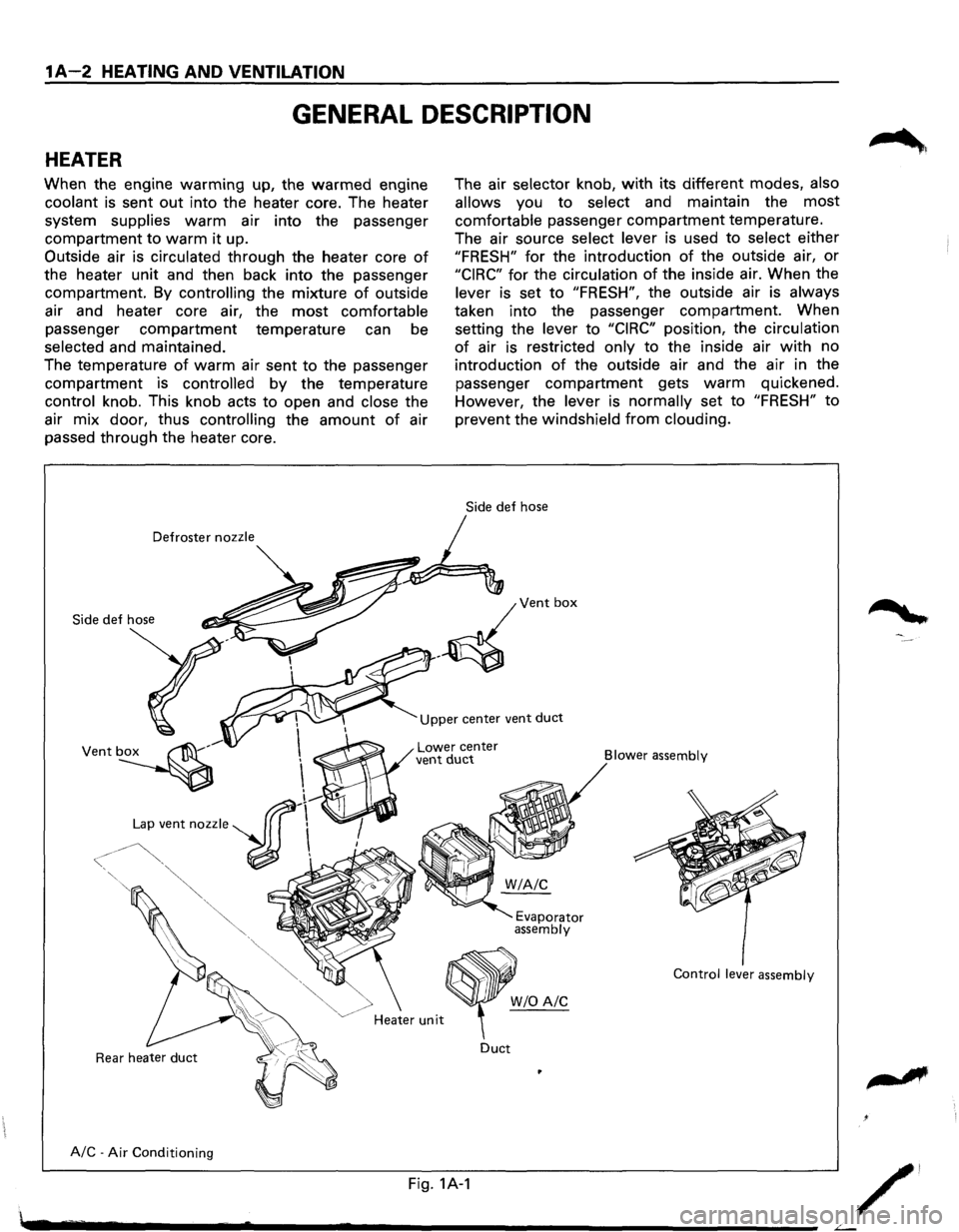
HEATER
When the engine warming up, the warmed engine
coolant is sent out into the heater core. The heater
system
supplies warm air into the passenger
compartment to warm it up.
Outside air is
circulated through the heater core of
the heater unit and then back into the passenger
compartment. By
controlling the mixture of outside
air and heater core air, the
most comfortable
passenger compartment temperature can be
selected and maintained.
The temperature
of warm air sent to the passenger
compartment is controlled by the temperature
control knob. This knob acts to open and close the
air
mix door, thus controlling the amount of air
passed through the heater core.
Defroster nozzle
Side
def hose
The air selector knob, with its different modes, also
allows
you to select and maintain the most
comfortable passenger compartment temperature.
The air source
select lever is used to select either
"FRESH" for the introduction of the outside air, or
"CIRC" for the circulation of the inside air. When the
lever is set to "FRESH", the outside air is always
taken into the passenger compartment. When
setting the
lever to "CIRC" position, the circulation
of air is restricted only to the inside air with no
introduction
of the outside air and the air in the
passenger
compartment gets warm quickened.
However, the
lever is normally set to "FRESH" to
prevent the windshield from clouding.
Upper center vent duct
A/C-Air Conditioning Lower
center vent duct
<
Heater unit
Duct
Fig. 1A-1
Blower
assembly
Evaporator assembly
Control lever assembly
W/0 A/C
/'
Page 33 of 1928
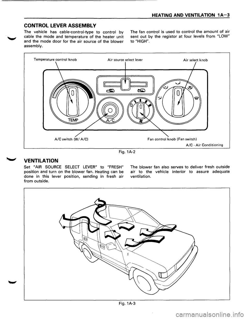
CONTROL LEVER ASSEMBL V
The vehicle has cable-control-type to control by
cable the mode and temperature of the heater unit
and the mode door for the air source of the blower
assembly.
HEATING AND VENTILATION 1A-3
The fan control is used to control the amount of air
sent
out by the registor at four levels from "LOW"
to "HIGH".
Temperature control knob Air source select lever Air select knob
A/C switch (WI A/C) Fan control knob (Fan switch)
A/C-Air Conditioning
Fig. 1A-2
,__,.. VENTILATION
Set "AIR SOURCE SELECT LEVER" to "FRESH"
position and turn on the blower fan. Heating can be
done in this
lever position, sending in fresh air
from outside. The
blower fan also serves
to deliver fresh outside
air
to the vehicle interior to assure adequate
ventilation.
Fig. 1A-3
Page 34 of 1928
1A-4 HEATING AND VENTILATION
AIR SELECT KNOB
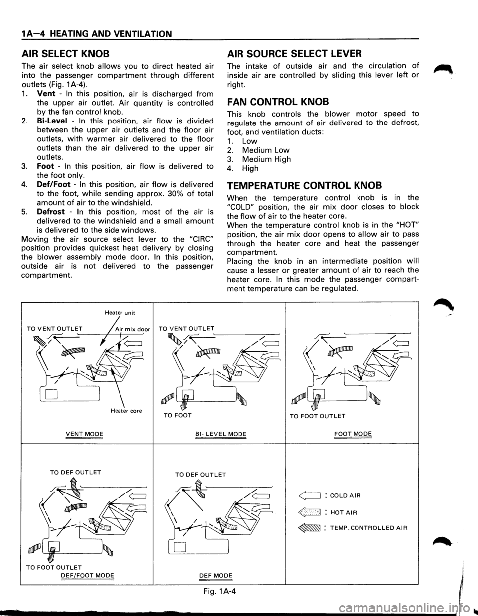
The air select knob allows you to direct heated air
into the passenger
compartment through different
outlets (Fig. 1A-4).
1. Vent -In this position, air is discharged from
the upper air
outlet. Air quantity is controlled
by the fan control knob.
2. Bi-Level -In this position, air flow is divided
between the upper air
outlets and the floor air
outlets, with warmer air delivered to the floor
outlets
than the air delivered to the upper air
outlets.
3. Foot -In this position, air flow is delivered to
the foot only.
4. Def/Foot -In this position, air flow is delivered
to the foot, while sending approx. 30% of total
amount of air to the windshield.
5. Defrost -In this position, most of the air is
delivered to the windshield and a small amount
is delivered to the side windows.
Moving the air source select lever to the "CIRC"
position provides quickest heat delivery by closing
the blower assembly mode door. In this position,
outside air
is not delivered to the passenger
compartment.
Heater unit
D
Heater core TO FOOT
AIR SOURCE SELECT LEVER
The intake of outside air and the circulation of
inside air are controlled by sliding this lever left or
right.
FAN CONTROL KNOB
This knob controls the blower motor speed to
regulate the amount of air delivered to the defrost,
foot, and
ventilation ducts:
1. Low
2. Medium Low
3. Medium High
4. High
TEMPERATURE CONTROL KNOB
When the temperature control knob is in the
"COLD" position, the air mix door closes to block
the flow of air to the heater core.
When the temperature
control knob is in the "HOT"
position, the air mix door opens to allow air to pass
through the heater core and heat the passenger
compartment.
Placing the knob in an intermediate position will
cause a lesser or greater amount of air to reach the
heater core.
In this mode the passenger compart
ment temperature can be regulated.
.r.( /
<_;~~
'--'R!I=---_____.J'
TO FOOT OUTLET
VENT MODE 81-LEVEL MODE FOOT MODE
TO FOOT OUTLET
DEF/FOOT MODE DEF MODE
Fig. 1A-4
<==:J : COLD AIR
~: HOTAIR
~ : TEMP.CONTROLLED AIR
I ........................................................................\
...... ------------------~1
Page 35 of 1928
~~[II] BODY ENG. FRAME
HEATING AND VENTILATION 1A-5
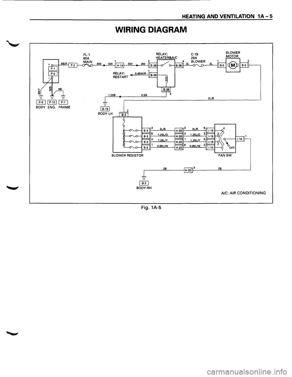
WIRING DIAGRAM
aw
RELAY;
RESTART
1.258
I 8-1el BODY-LH
0.58 2LJ8
BLOWER RESISTOR
r------'2::.::8:,__ __ _,H-201~4 ____ __,2""8 _____ __,
~ BODY-RH
AJC: AIR CONDITIONING
Fig. 1A-5
Page 36 of 1928
1A-6 HEATING AND VENTILATION
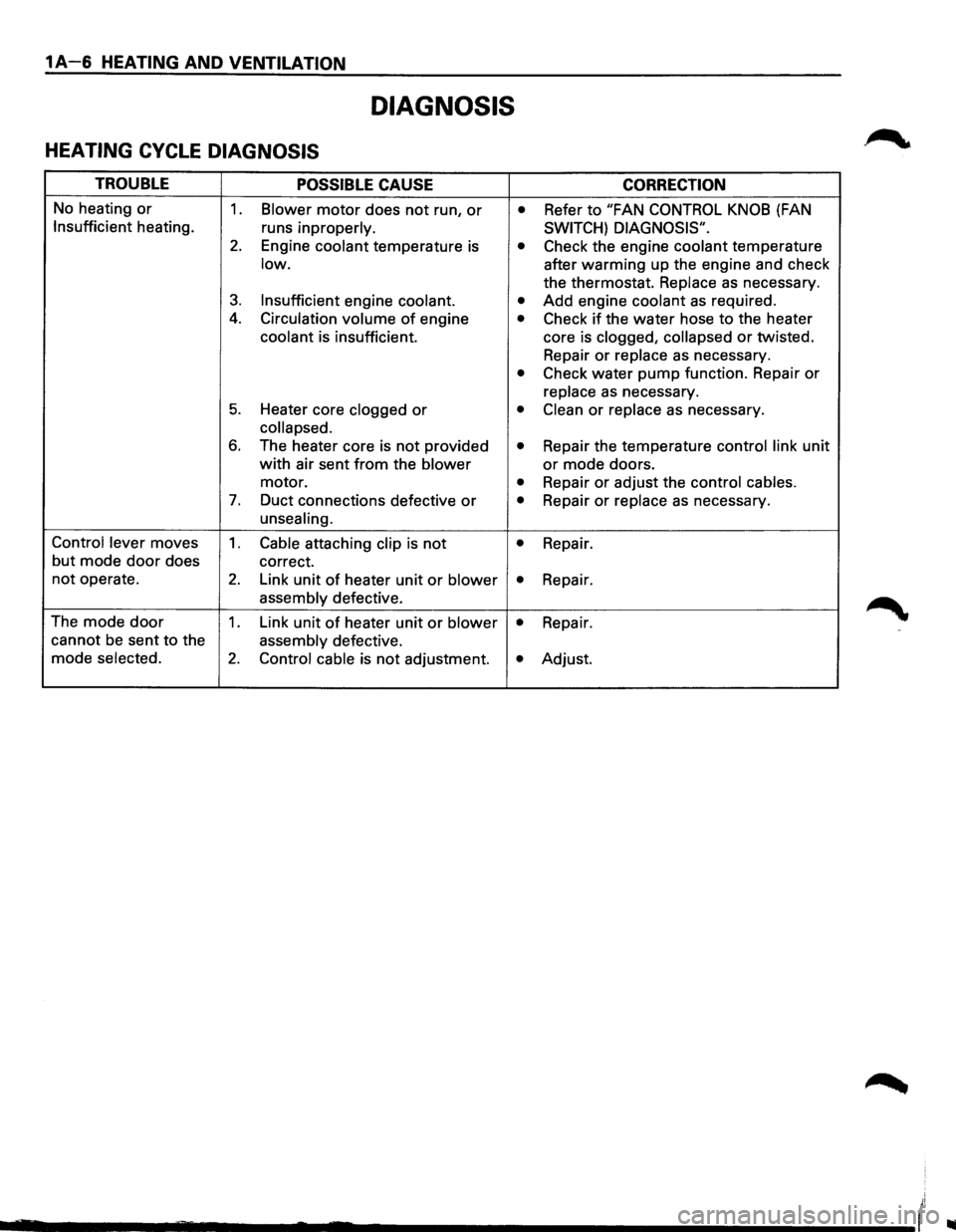
DIAGNOSIS
HEATING CYCLE DIAGNOSIS
TROUBLE POSSIBLE CAUSE CORRECTION
No heating or 1. Blower motor does not run, or • Refer to "FAN CONTROL KNOB (FAN
Insufficient heating.
runs inproperly. SWITCH) DIAGNOSIS".
2. Engine coolant temperature is • Check the engine coolant temperature
low. after warming up the engine and check
the thermostat.
Replace as necessary.
3. Insufficient engine coolant. • Add engine coolant as required .
4. Circulation volume of engine • Check if the water hose to the heater
coolant is insufficient. core is clogged, collapsed or twisted.
Repair
or replace as necessary.
• Check water pump function. Repair or
replace as necessary.
5. Heater core clogged or • Clean or replace as necessary.
collapsed.
6. The heater core is not provided • Repair the temperature control link unit
with air sent from the blower or mode doors.
motor.
• Repair or adjust the control cables.
7. Duct connections defective or • Repair or replace as necessary.
unsealing.
Control lever
moves 1. Cable attaching clip is not • Repair.
but
mode door does correct.
not operate. 2. Link unit of heater unit or blower • Repair.
assembly defective.
The
mode door 1. Link unit of heater unit or blower • Repair.
cannot
be sent to the assembly defective.
mode
selected. 2. Control cable is not adjustment. • Adjust.
_______ __... ..... ..._ ____________ (
Page 37 of 1928
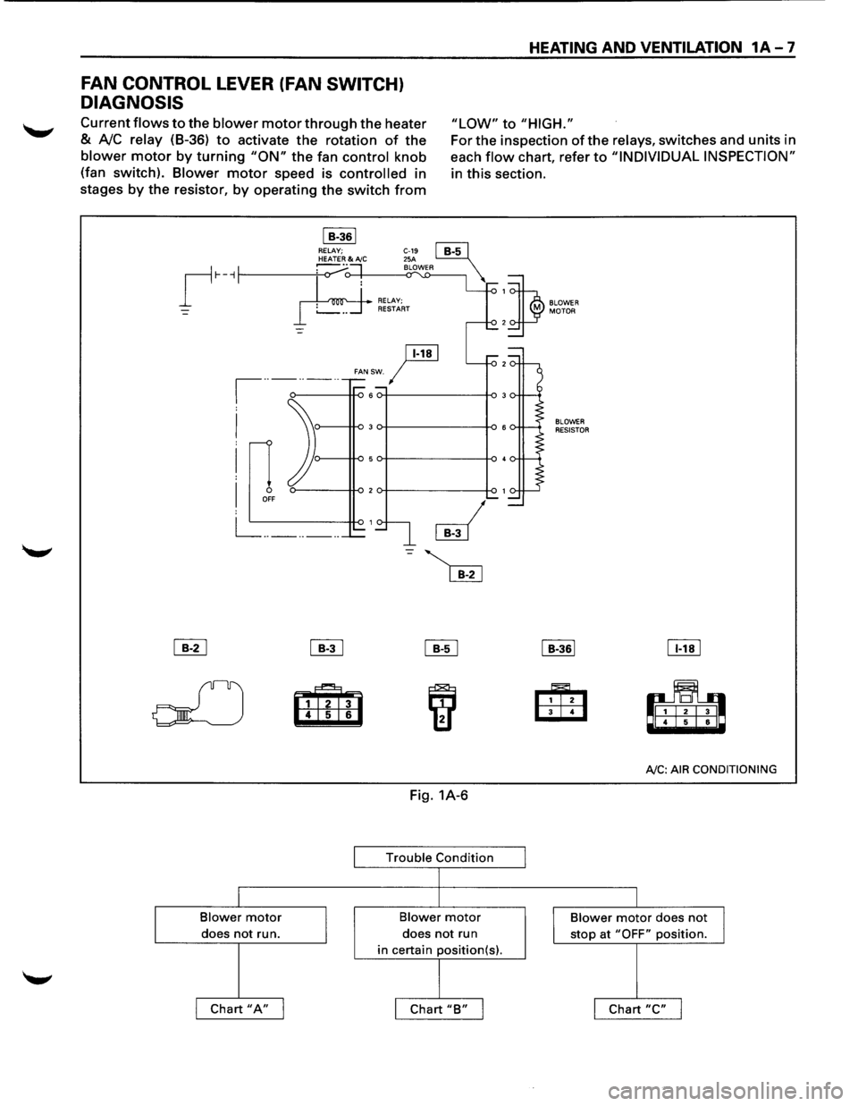
FAN CONTROL LEVER (FAN SWITCH)
DIAGNOSIS
HEATING AND VENTILATION 1A-7
Current flows to the blower motor through the heater
& A!C relay (8-36) to activate the rotation of the
blower motor by turning "ON" the fan control knob
(fan switch).
Blower motor speed is controlled in
stages
by the resistor, by operating the switch from
"LOW" to "HIGH."
I B-361 RELAY;
ji!!J
For the inspection of the relays, switches and units in
each
flow chart, refer to "INDIVIDUAL INSPECTION"
in this section.
1
)
BLOWER MOTOR 2
r-··-··-··
FANSW. I
I
I
I
0 OFF
L= _______ _
~ ~
olJ m 6
I
Blower motor
I does not run.
I Chart "A" I
~
iif1
Fig. 1A-6
Trouble Condition
I
l
Blower motor
does not run
in certain position(s).
I
I Chart "B" I I
BLOWER RESISTOR
I B-361
Eili3 4
IT!!]
rl! 6
AJC: AIR
CONDITIONING
I
Blower motor does not
J stop at "OFF" position.
I Chart "C" I
Page 38 of 1928
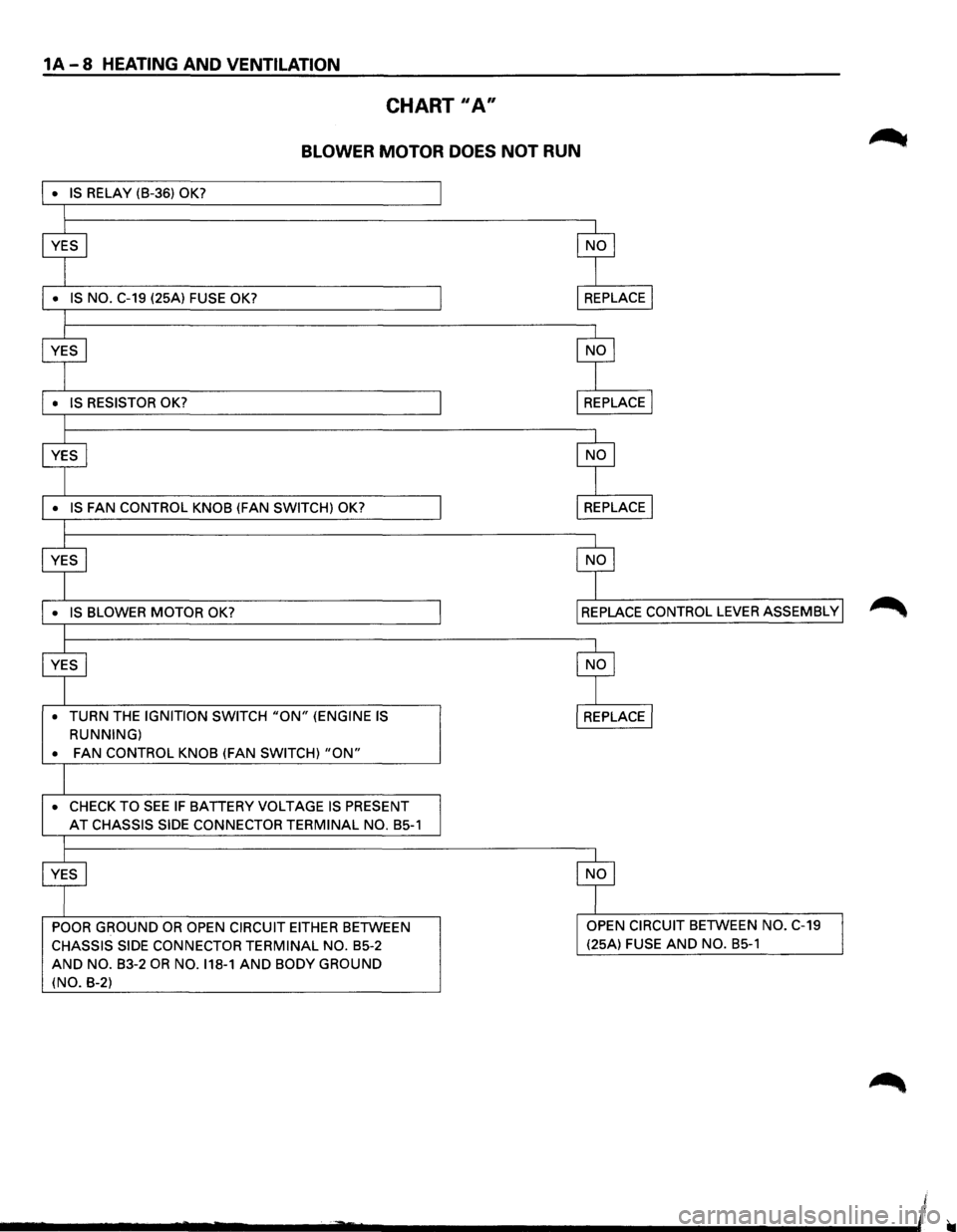
1A-8 HEATING AND VENTILATION
CHART II A"
BLOWER MOTOR DOES NOT RUN
• TURN THE IGNITION SWITCH "ON" (ENGINE IS
RUNNING)
•
FAN CONTROL KNOB (FAN SWITCH) "ON"
• CHECK TO SEE IF BATTERY VOLTAGE IS PRESENT
AT CHASSIS SIDE CONNECTOR TERMINAL NO. B5-1
POOR GROUND OR OPEN CIRCUIT EITHER BETWEEN
CHASSIS SIDE CONNECTOR TERMINAL NO. B5-2
AND NO. B3-2 OR NO. 118-1 AND BODY GROUND
(NO. B-2) (25A)
FUSE AND NO. B5-1