check engine ISUZU TROOPER 1995 Service Manual
[x] Cancel search | Manufacturer: ISUZU, Model Year: 1995, Model line: TROOPER, Model: ISUZU TROOPER 1995Pages: 1928
Page 455 of 1928
![ISUZU TROOPER 1995 Service Manual CHART A-5, TA-5 I):Eet<(] I TECH 1 I
5) BRAKING SOUND (FROM HYDRAULIC UNIT) IS HEARD WHILE NOT BRAKING
IS THIS THE FIRST VEHICLE START AFTER ENGINE
START? AND IS VEHICLE SPEED UNDER 10 KM/H](/img/61/57183/w960_57183-454.png "ISUZU TROOPER 1995 Service Manual CHART A-5, TA-5 I):Eet<(] I TECH 1 I
5) BRAKING SOUND (FROM HYDRAULIC UNIT) IS HEARD WHILE NOT BRAKING
IS THIS THE FIRST VEHICLE START AFTER ENGINE
START? AND IS VEHICLE SPEED UNDER 10 KM/H")
CHART A-5, TA-5 I):Eet<(] I TECH 1 I
5) BRAKING SOUND (FROM HYDRAULIC UNIT) IS HEARD WHILE NOT BRAKING
IS THIS THE FIRST VEHICLE START AFTER ENGINE
START? AND IS VEHICLE SPEED UNDER 10 KM/H
(6MPH)?
WHEN
DID IT OCCUR? 1. AT THE TIME OF SHIFT DOWN OR CLUTCH OPERATION 2. AT THE TIME OF LOW J.l DRIVE (ICE OR SNOW ROAD) OR ROUGH ROAD DRIVE 3. AT THE TIME OF HIGH-SPEED TURN 4. AT THE TIME OF PASSING CURB 5. AT THE TIME OF OPERATING ELECTRICAL
EQUIPMENT SWITCHES
6. AT THE TIME OF RACING THE ENGINE (OVER
5000 RPM)
IS THERE PLAY IN EACH SENSOR/WHEEL
SPEED SENSOR RINGS?
•
CHECK HARNESS/CONNECTOR FOR SUSPECTED
DISCONNECTION
• IF NO DISCONNECTION IS FOUND,
REPLACE EBCM
IT IS SELF-CHECKING SOUND NORMAL
UNDER ANY ONE CONDITION ABOVE, ABS MAY SOMETIME BE ACTUATED EVEN WHEN BRAKE
PEDAL IS NOT APPLIED
11 = Friction Unit
Page 460 of 1928
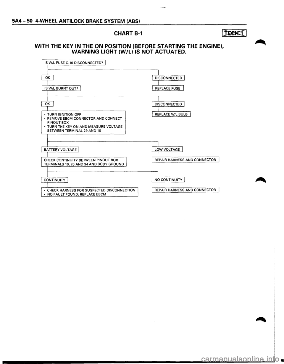
5A4-50 4-WHEEL ANTILOCK BRAKE SYSTEM (ABS)
CHART B-1
WITH THE KEY IN THE ON POSITION (BEFORE STARTING THE ENGINE),
WARNING LIGHT
{W/L) IS NOT ACTUATED.
IS W/L FUSE C-10 DISCONNECTED? j
I
IS W/L BURNT OUT? I
I
• TURN IGNITION OFF
• REMOVE EBCM CONNECTOR AND CONNECT PINOUT BOX
• TURN THE KEY ON AND MEASURE VOLTAGE BETWEEN TERMINAL 29 AND 10
I
I
BATTERYVOLTAGE I
I
CHECK CONTINUITY BETWEEN PINOUT BOX I TERMINALS 10, 20 AND 34 AND BODY GROUND
l
I CONTINUITY I
I • CHECK HARNESS FOR SUSPECTED DISCONNECTION I • NO FAULT FOUND: REPLACE EBCM
I
I
DISCONNECTED I
I L REPLACE FUSE J
I L DISCONNECTED J
I I REPLACE W/L BULB I
I
I
LOWVOLTAGE I
I
I
REPAIR HARNESS AND CONNECTOR I
I
I
NO CONTINUITY I
I I REPAIR HARNESS AND CONNECTOR I
•
Page 500 of 1928
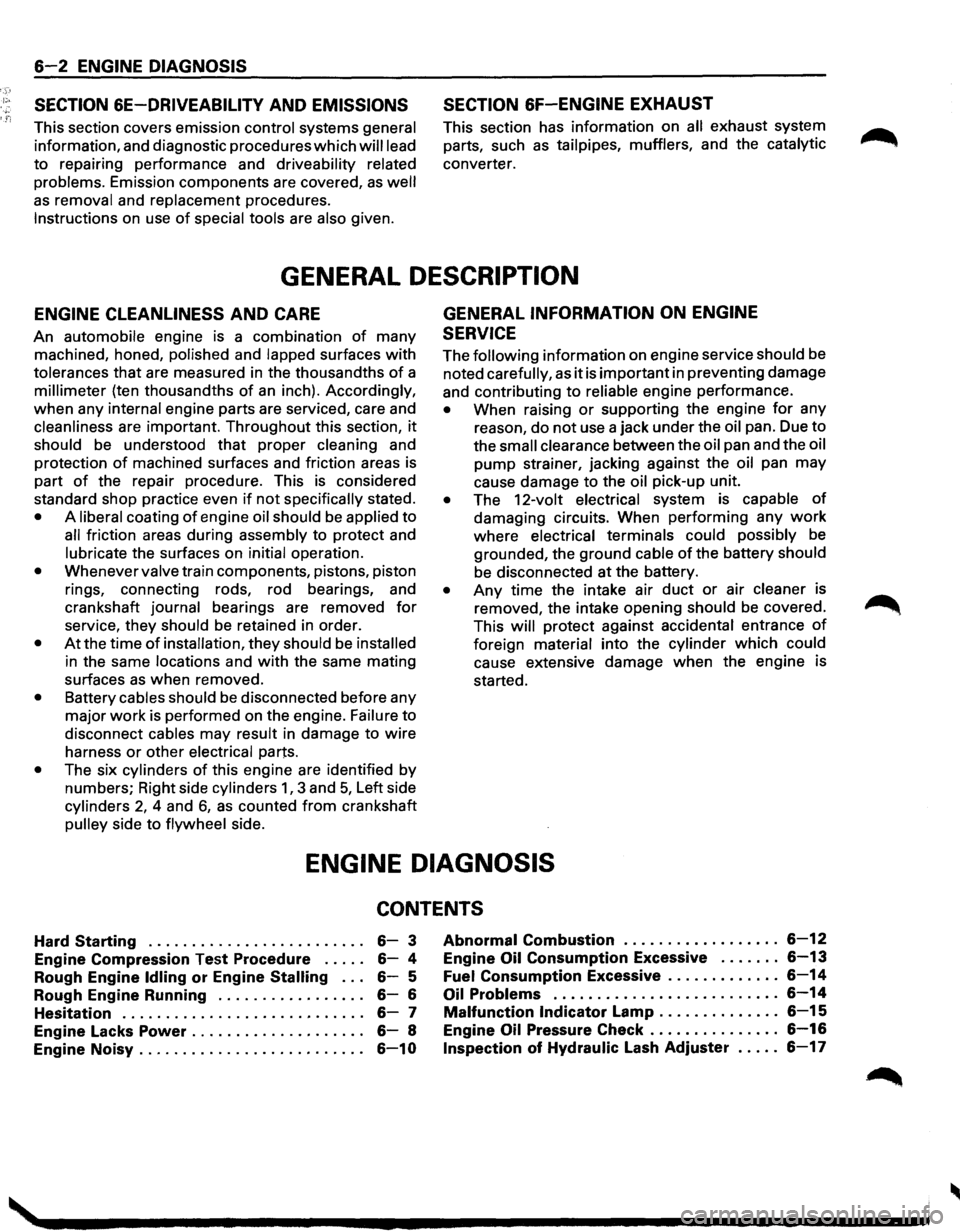
6-2 ENGINE DIAGNOSIS
SECTION 6E-DRIVEABILITY
AND EMISSIONS
This section covers emission control systems general
information, and diagnostic procedures which will lead
to repairing performance and driveability related
problems.
Emission components are covered, as well
as removal and replacement procedures.
Instructions on use
of special tools are also given.
SECTION 6F-ENGINE EXHAUST
This section has information on all exhaust system
parts, such
as tailpipes, mufflers, and the catalytic
converter.
GENERAL DESCRIPTION
ENGINE CLEANLINESS AND CARE
An automobile engine is a combination of many
machined, honed,
polished and lapped surfaces with
tolerances that are measured in the thousandths of a
millimeter (ten thousandths of an inch). Accordingly,
when any
internal engine parts are serviced, care and
cleanliness are important. Throughout this section, it
should be understood that proper cleaning and
protection
of machined surfaces and friction areas is
part
of the repair procedure. This is considered
standard shop practice even
if not specifically stated.
• A liberal coating of engine oil should be applied to
all friction areas during assembly to protect and
lubricate the surfaces on initial operation.
• Whenever valve train components, pistons, piston
rings, connecting rods, rod bearings, and
crankshaft
journal bearings are removed for
service, they should be retained in order.
• At the time of installation, they should be installed
in the same locations and with the same mating
surfaces
as when removed.
• Battery cables should be disconnected before any
major
work is performed on the engine. Failure to
disconnect
cables may result in damage to wire
harness
or other electrical parts.
• The six cylinders of this engine are identified by
numbers; Right side
cylinders 1, 3 and 5, Left side
cylinders 2, 4 and 6, as counted from crankshaft
pulley side to flywheel side.
GENERAL INFORMATION ON ENGINE
SERVICE
The following information on engine service should be
noted
carefully, as it is important in preventing damage
and contributing
to reliable engine performance.
• When raising or supporting the engine for any
reason,
do not use a jack under the oil pan. Due to
the
small clearance between the oil pan and the oil
pump strainer, jacking against the oil pan may
cause damage to the
oil pick-up unit.
• The 12-volt electrical system is capable of
damaging circuits. When performing any work
where electrical terminals could possibly be
grounded, the ground cable of the battery should
be disconnected at the battery.
• Any time the intake air duct or air cleaner is
removed, the intake opening
should be covered.
This
will protect against accidental entrance of
foreign material into the cylinder which could
cause extensive damage when the engine is
started.
ENGINE DIAGNOSIS
CONTENTS
Hard Starting . . . . . . . . . . . . . . . . . . . . . . . . . 6-3
Engine Compression
Test Procedure ..... 6-4
Rough Engine
Idling or Engine Stalling . . . 6-5
Rough Engine Running . . . . . . . . . . . . . . . . .
6-6
Hesitation . . . . . . . . . . . . . . . . . . . . . . . . . . . . 6-7
Engine Lacks
Power . . . . . . . . . . . . . . . . . . . . 6-8
Engine
Noisy .......................... 6-10
Abnormal Combustion . . . . . . . . . . . . . . . . . . 6-12
Engine Oil Consumption Excessive . . . . . . . 6-13
Fuel Consumption Excessive ............. 6-14
Oil Problems . . . . . . . . . . . . . . . . . . . . . . . . . . 6-14
Malfunction Indicator Lamp . . . . . . . . . . . . . . 6-15
Engine Oil Pressure Check ............... 6-16
Inspection of Hydraulic Lash Adjuster . . . . . 6-17
Page 501 of 1928
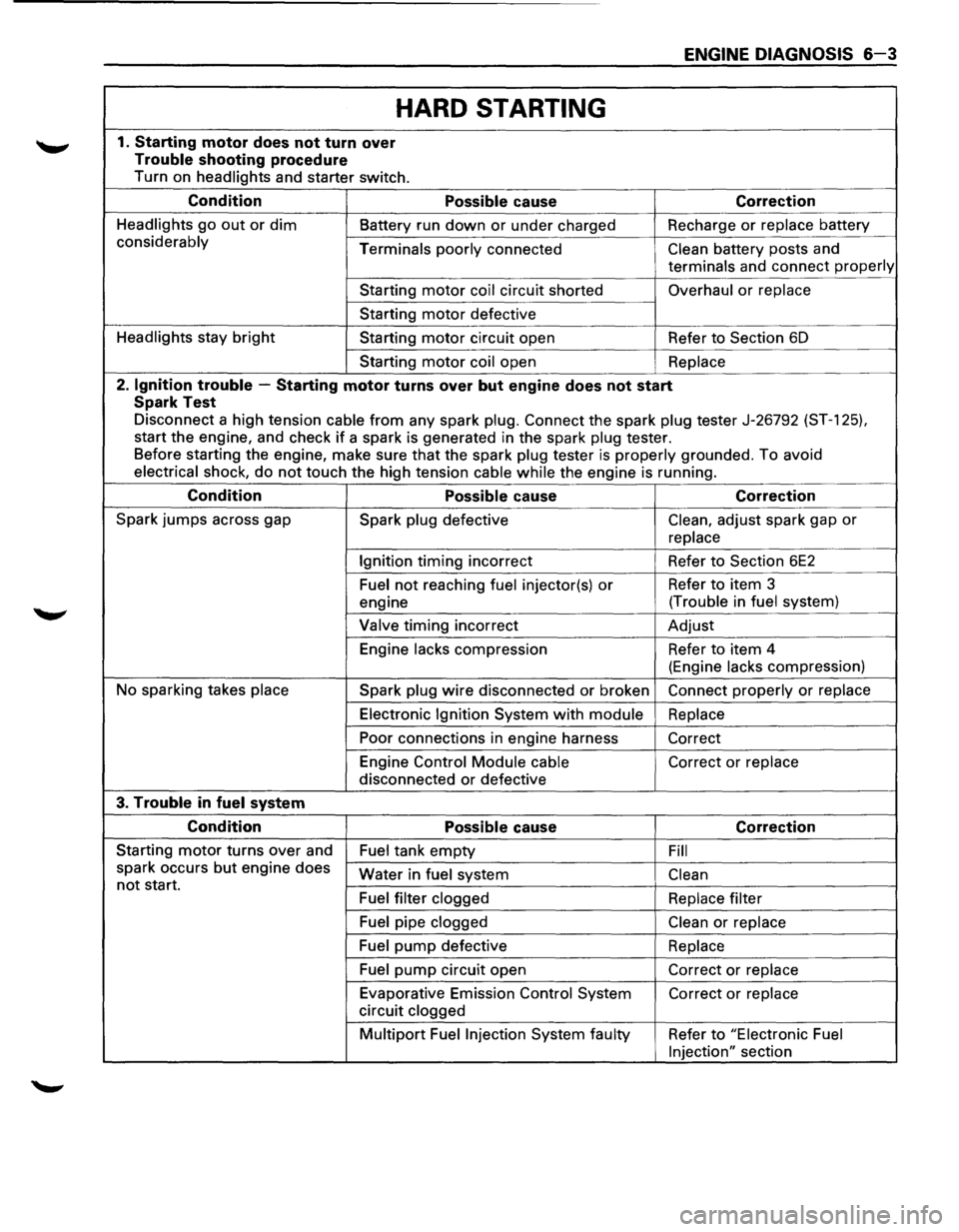
ENGINE DIAGNOSIS 6-3
HARD STARTING
1. Starting motor does not turn over
Trouble shooting procedure
Turn on headlights and starter switch.
Condition Possible cause Correction
Headlights go out or dim Battery run down or under charged Recharge or replace battery
considerably
Terminals poorly connected Clean battery posts and
terminals and connect properly
Starting motor coil circuit shorted Overhaul or replace
Starting motor defective
Headlights stay
bright Starting motor circuit open Refer to Section 6D
Starting
motor coil open Replace
2. Ignition trouble -Starting motor turns over but engine does not start
Spark Test
Disconnect a high tension cable from any spark plug. Connect the spark plug tester J-26792 (ST-1 25).
start the engine, and check if a spark is generated in the spark plug tester.
Before starting the engine, make sure
that the spark plug tester is properly grounded. To avoid
electrical shock, do not touch the high tension cable while the engine is running.
Condition Possible cause Correction
Spark jumps across gap
Spark plug defective Clean, adjust spark gap or
replace
Ignition
timing incorrect Refer to Section 6E2
Fuel not reaching fuel injector(s) or Refer to item 3
engine (Trouble
in
fuel system)
Valve
timing incorrect Adjust
Engine
lacks compression Refer to item 4
(Engine
lacks compression)
No sparking takes
place Spark plug wire disconnected or broken Connect properly or replace
Electronic Ignition System with module Replace
Poor connections in engine harness
Correct
Engine Control
Module cable Correct or replace
disconnected or defective
3. Trouble in fuel system
Condition Possible cause Correction
Starting motor turns over and
Fuel tank empty Fill
spark occurs but engine does
not start. Water in fuel system Clean
Fuel filter clogged Replace filter
Fuel pipe clogged Clean or replace
Fuel pump defective
Replace
Fuel
pump circuit open Correct or replace
Evaporative Emission Control System Correct or replace
circuit clogged
Multipart Fuel Injection System faulty Refer to "Electronic Fuel
Injection"
section
Page 502 of 1928
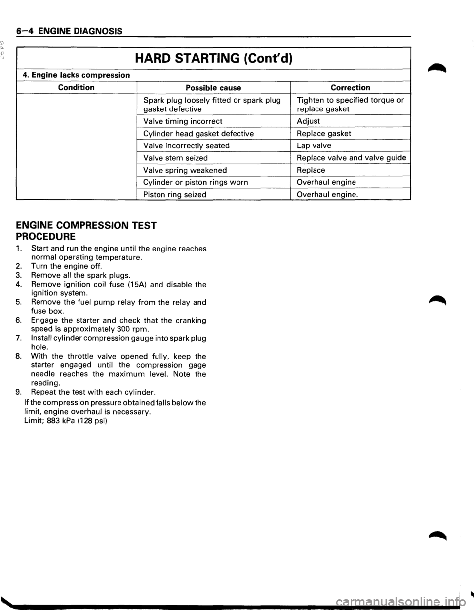
6-4 ENGINE DIAGNOSIS
HARD STARTING (Cont'd)
4. Engine lacks compression
Condition Possible cause
Spark plug loosely fitted or spark plug
gasket defective
Valve timing incorrect
Cylinder head gasket defective
Valve incorrectly seated
Valve stem seized
Valve spring weakened
Cylinder or piston rings worn
Piston ring seized
ENGINE COMPRESSION TEST
PROCEDURE
1. Start and run the engine until the engine reaches
normal operating temperature.
2. Turn the engine off.
3. Remove all the spark plugs.
4. Remove ignition coil fuse (15A) and disable the
ignition system.
5. Remove the fuel pump relay from the relay and
fuse box.
6. Engage the starter and check that the cranking
speed is approximately
300 rpm.
7. Install cylinder compression gauge into spark plug
hole.
8. With the throttle valve opened fully, keep the
starter engaged
until the compression gage
needle reaches the
maximum level. Note the
reading.
9. Repeat the test with each cylinder.
If
the compression pressure obtained falls below the
limit, engine overhaul is necessary.
Limit; 883
kPa (128 psi) Correction
Tighten
to specified torque or
replace gasket
Adjust
Replace gasket
Lap
valve
Replace valve
and valve guide
Replace
Overhaul engine
Overhaul engine.
Page 505 of 1928
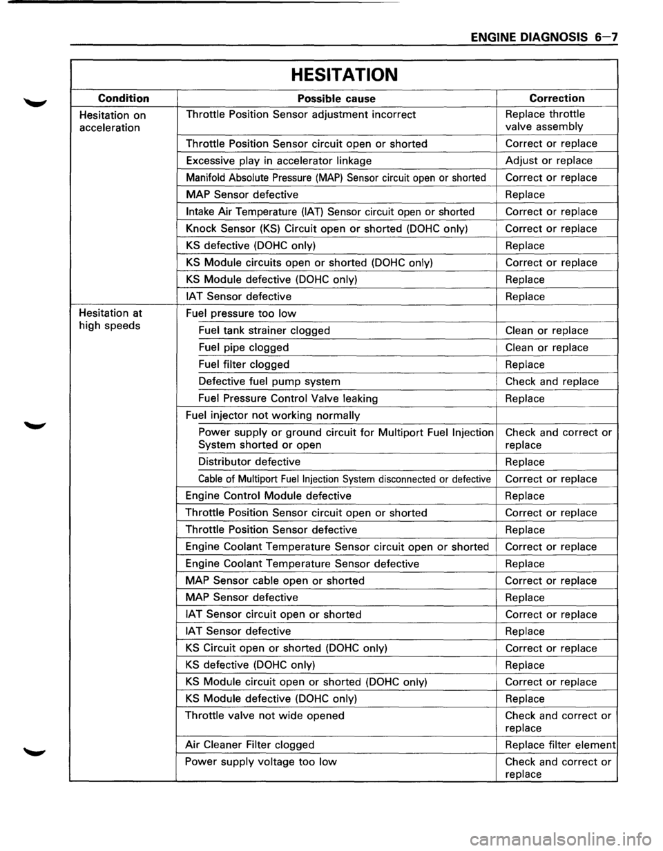
ENGINE DIAGNOSIS 6-7
HESITATION
Condition Possible cause Correction
Hesitation on Throttle
Position Sensor adjustment incorrect Replace
throttle
acceleration valve
assembly
Throttle Position Sensor circuit open
or shorted Correct
or replace
Excessive play in accelerator linkage
Adjust or replace
Manifold Absolute
Pressure (MAP) Sensor circuit open or shorted Correct or replace
MAP Sensor defective Replace
Intake Air
Temperature (IAT) Sensor circuit open or shorted Correct or replace
Knock Sensor
(KS) Circuit open or shorted (DOHC only) Correct or replace
KS defective (DOHC only) Replace
KS Module circuits open or shorted (DOHC only) Correct or replace
KS Module defective (DOHC only) Replace
IAT Sensor defective Replace
Hesitation at
Fuel pressure
too low
high speeds
Fuel tank strainer clogged Clean or replace
Fuel pipe clogged
Clean or replace
Fuel filter clogged
Replace
Defective fuel
pump system Check and replace
Fuel Pressure Control Valve leaking Replace
Fuel injector
not working normally
Power supply or ground circuit for Multipart Fuel Injection Check and correct or
System shorted or open
replace
Distributor defective Replace
Cable of Multipart Fuel Injection System disconnected or defective Correct or replace
Engine Control Module defective Replace
Throttle Position Sensor circuit open
or shorted Correct or replace
Throttle Position Sensor defective Replace
Engine Coolant Temperature Sensor circuit open
or shorted Correct or replace
Engine Coolant Temperature Sensor defective Replace
MAP Sensor cable open
or shorted Correct or replace
MAP Sensor defective
Replace
IAT Sensor circuit open or shorted
Correct or replace
IAT Sensor defective Replace
KS Circuit open or shorted (DOHC only)
Correct or replace
KS defective (DOHC only) Replace
KS Module circuit open or shorted (DOHC only) Correct or replace
KS Module defective (DOHC only) Replace
Throttle valve
not wide opened
Check and correct or
replace
Air Cleaner Filter clogged
Replace filter element
Power supply voltage
too low Check and correct or
replace
Page 513 of 1928
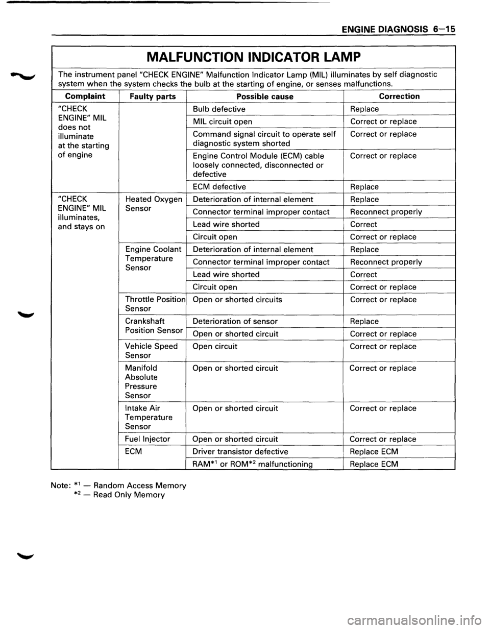
ENGINE DIAGNOSIS 6-15
MALFUNCTION INDICATOR LAMP
The instrument panei"CHECK ENGINE" Malfunction Indicator Lamp (MIL) illuminates by self diagnostic
system
when the system checks the bulb at the starting of engine, or senses malfunctions.
Complaint
Faulty parts
"CHECK
ENGINE" MIL
does not
illuminate
at the starting
of engine
"CHECK Heated Oxygen
ENGINE" MIL Sensor
illuminates,
and stays on
Engine
Coolant
Temperature Sensor
Throttle Position
Sensor
Crankshaft Position Sensor
Vehicle Speed
Sensor
Manifold
Absolute
Pressure Sensor
Intake Air
Temperature Sensor
Fuel Injector
ECM
Note: *1
-Random Access Memory
*2
-Read Only Memory
Possible cause Correction
Bulb defective Replace
MIL
circuit open Correct or replace
Command signal
circuit to operate self Correct or replace
diagnostic system shorted
Engine
Control Module (ECM) cable Correct or replace
loosely
connected, disconnected or
defective
ECM defective Replace
Deterioration of internal element Replace
Connector terminal improper contact Reconnect properly
Lead wire shorted Correct
Circuit
open Correct or replace
Deterioration of internal element Replace
Connector terminal improper contact Reconnect properly
Lead wire shorted Correct
Circuit
open Correct or replace
Open
or shorted circuits Correct or replace
Deterioration of sensor Replace
Open
or shorted circuit Correct or replace
Open
circuit Correct or replace
Open
or shorted circuit Correct or replace
Open
or shorted circuit Correct or replace
Open
or shorted circuit Correct or replace
Driver transistor defective Replace ECM
RAM*1 or ROM*2 malfunctioning Replace ECM
Page 514 of 1928
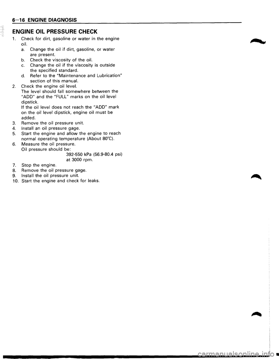
6-16 ENGINE DIAGNOSIS
ENGINE OIL PRESSURE CHECK
1. Check for dirt, gasoline or water in the engine
oil.
a. Change the oil if dirt, gasoline, or water
are present.
b. Check the viscosity of the oil.
c. Change the oil if the viscosity is outside
the specified standard.
d. Refer to the "Maintenance and Lubrication"
section of this manual.
2. Check the engine oil level.
The level should fall somewhere between the
"ADD" and the "FULL" marks on the oil level
dipstick.
If the oil level does not reach the "ADD" mark
on the
oil level dipstick, engine oil must be
added.
3. Remove the oil pressure unit.
4. Install an oil pressure gage.
5. Start the engine and allow the engine to reach
normal operating temperature (About 80°C).
6. Measure the oil pressure.
Oil pressure should be:
7. Stop the engine.
392-550 kPa (56.9-80.4 psi)
at
3000 rpm.
8. Remove the oil pressure gage.
9. Install the oil pressure unit.
10. Start the engine and check for leaks.
m ... cw
•
Page 522 of 1928
6A-6 GENERAL ENGINE MECHANICAL
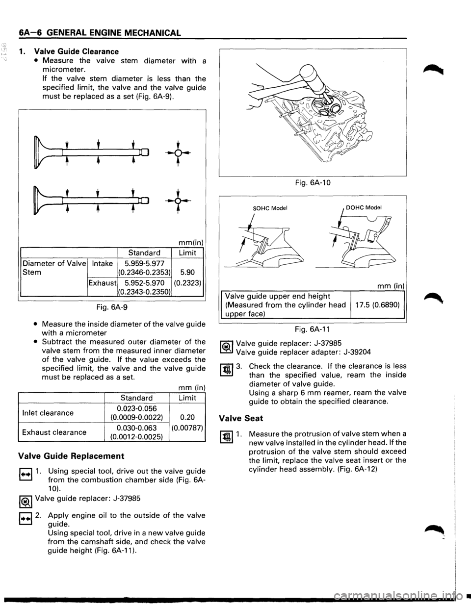
1. Valve Guide Clearance
• Measure the valve stem diameter with a
micrometer.
If the valve stem diameter is less than the
specified
limit, the valve and the valve guide
must be replaced as a set (Fig. 6A-9).
~
1: : !o:J
+
~ li : :~
+
mm(in)
Standard Limit
Diameter
of Valve Intake 5.959-5.977
Stem (0.2346-0.2353)
5.90
Exhaust 5.952-5.970 (0.2323)
(0.2343-0.2350)
Fig. 6A-9
• Measure
the inside diameter of the valve guide
with a micrometer
• Subtract the measured outer diameter of the
valve stem from the measured inner diameter
of the valve guide. If the value exceeds the
specified
limit, the valve and the valve guide
must be replaced as a set.
mm (in)
Standard Limit
Inlet
clearance 0.023-0.056
(0.0009-0.0022) 0.20
Exhaust clearance 0.030-0.063
(0.00787)
(0.0012-0.0025)
Valve Guide Replacement
r::l 1. Using special tool, drive out the valve guide
L::.l from the combustion chamber side (Fig. 6A-
10).
1®..1 Valve guide replacer: J-37985
1••12. Apply engine oil to the outside of the valve
guide.
Using
special tool, drive in a new valve guide
from the camshaft side, and check the valve
guide height (Fig. 6A-11 ).
Fig. 6A-1 0
SOHC Model
mm (in)
Valve guide upper end height
(Measured from the
cylinder head 17.5 (0.6890)
upper face)
Fig. 6A-11
li0\1 Valve guide replacer: J-37985
~ Valve guide replacer adapter: J-39204
~3. Check the clearance. If the clearance is less
than the specified value, ream the inside
diameter
of valve guide.
Using a sharp 6
mm reamer, ream the valve
guide to obtain the specified clearance.
Valve Seat
~1. Measure the protrusion of valve stem when a
new valve installed in the cylinder head. If the
protrusion
of the valve stem should exceed
the
limit, replace the valve seat insert or the
cylinder head assembly. (Fig. 6A-12)
•
Page 523 of 1928
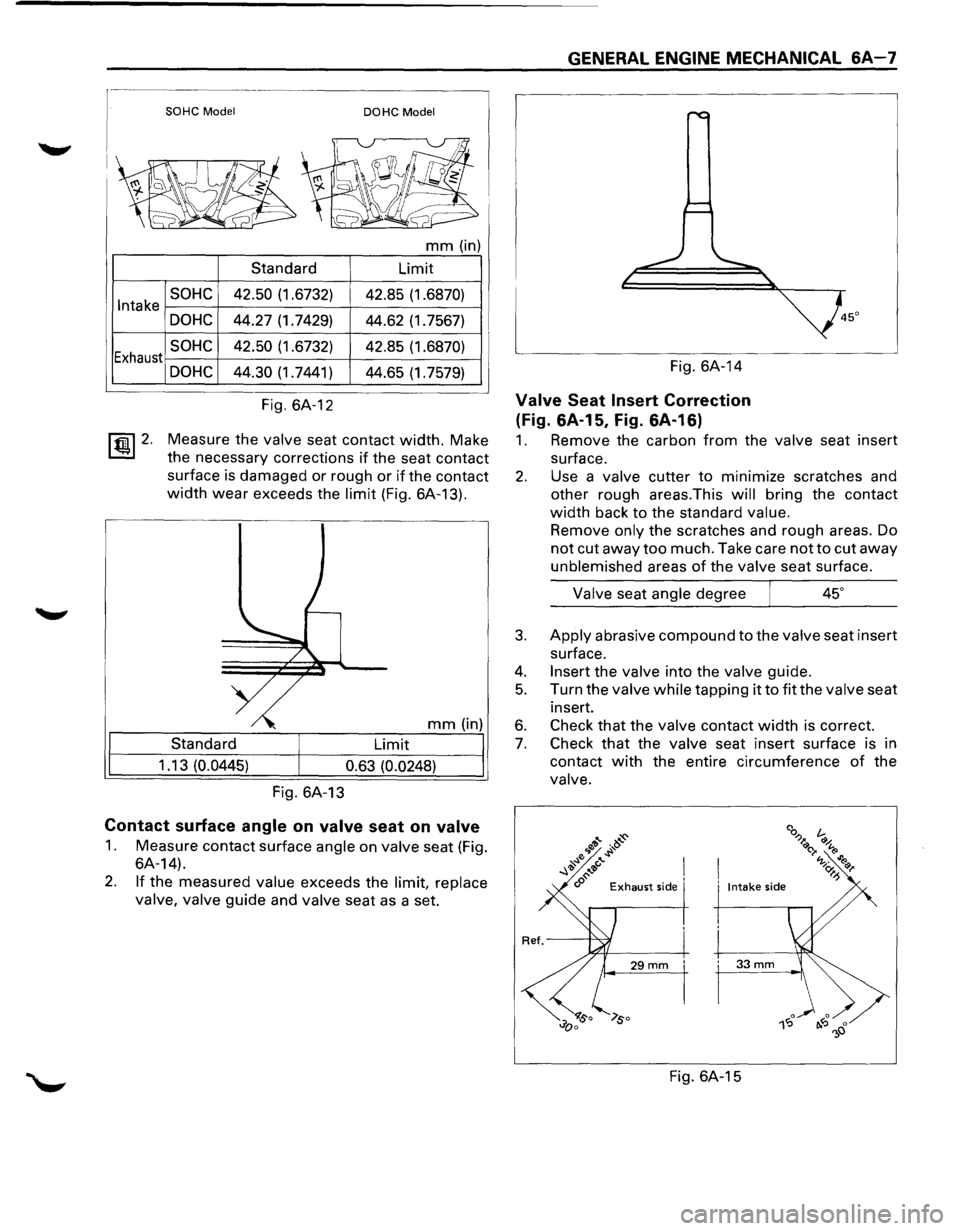
Intake
Exhaust
~ 2.
SOHC Model DOHC Model
mm (in)
Standard Limit
SOHC 42.50 (1.6732)
42.85 (1.6870)
DOHC 44.27 (1.7429)
44.62 (1.7567)
SOHC 42.50 (1.6732) 42.85 (1.6870)
DOHC 44.30 (1.7441) 44.65 (1.7579)
Fig. 6A-12
Measure the
valve seat contact width. Make
the necessary corrections
if the seat contact
surface is damaged or rough
or if the contact
width wear exceeds the limit (Fig. 6A-13).
mm (in)
Standard Limit
1 .13
(0.0445)
0.63 (0.0248)
Fig. 6A-13
Contact surface angle on valve seat on valve
1. Measure contact surface angle on valve seat (Fig.
6A-14).
2. If the measured value exceeds the limit, replace
valve, valve
guide and valve seat as a set.
GENERAL ENGINE MECHANICAL 6A-7
Fig. 6A-14
Valve Seat Insert Correction
(Fig. 6A-15, Fig. 6A-16)
1. Remove the carbon from the valve seat insert
surface.
2. Use a valve cutter to minimize scratches and
other rough areas.This
will bring the contact
width back to the standard value.
Remove only the scratches and rough areas. Do
not cut away too much. Take care not to cut away
unblemished areas of the valve seat surface.
Valve seat angle degree
3. Apply abrasive compound to the valve seat insert
surface.
4. Insert the valve into the valve guide.
5. Turn the valve while tapping it to fit the valve seat
insert.
6. Check that the valve contact width is correct.
7. Check that the valve seat insert surface is in
contact
with the entire circumference of the
valve.
Fig. 6A-15