check engine ISUZU TROOPER 1995 User Guide
[x] Cancel search | Manufacturer: ISUZU, Model Year: 1995, Model line: TROOPER, Model: ISUZU TROOPER 1995Pages: 1928
Page 64 of 1928
18-10 AIR CONDITIONING
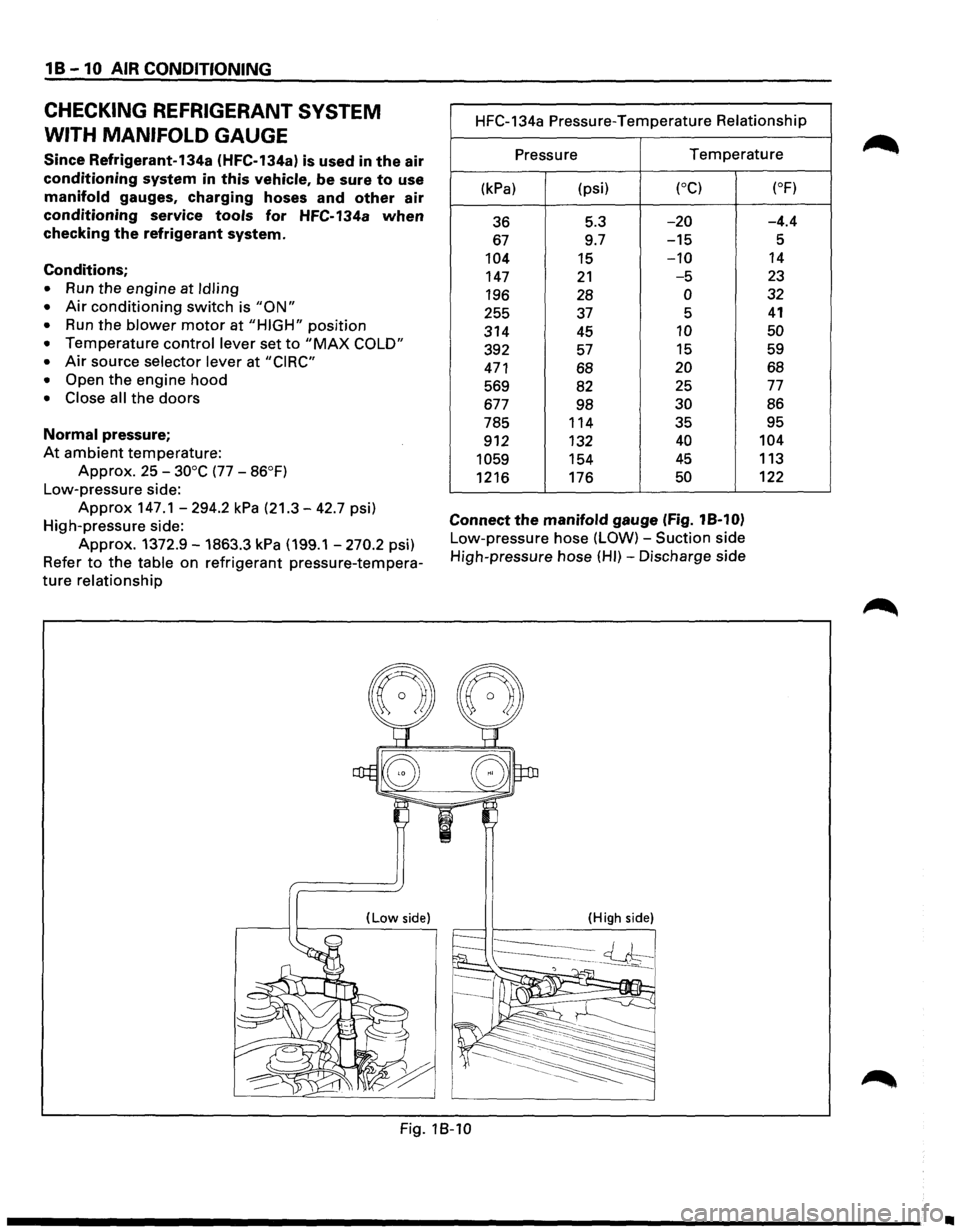
CHECKING REFRIGERANT SYSTEM
WITH MANIFOLD
GAUGE
Since Refrigerant-134a (HFC-134a) is used in the air
conditioning system in this vehicle, be sure to use
manifold gauges, charging hoses and other air
conditioning service tools for HFC-134a when
checking the refrigerant system.
Conditions;
• Run the engine at Idling
• Air conditioning switch is "ON"
• Run the blower motor at "HIGH" position
• Temperature control lever set to "MAX COLD"
•
Air source selector lever at "CIRC"
• Open
the engine hood
• Close all the doors
Normal pressure;
At ambient temperature:
Approx. 25 -30°C (77 -86°F)
Low-pressure side:
Approx 147.1-294.2 kPa (21.3-42.7 psi)
High-pressure side:
Approx. 1372.9-1863.3 kPa (199.1 -270.2 psi}
Refer
to the table on refrigerant pressure-tempera
ture relationship
(Low side)
HFC-134a Pressure-Temperature Relationship
Pressure
Temperature
(kPa) (psi) (oC)
36 5.3 -20
67 9.7 -15
104
15 -10
147 21 -5
196 28 0
255 37 5
314
45 10
392
57 15
471 68 20
569
82 25
677 98 30
785 114 35
912 132
40
1059 154 45
1216
176 50
Connect the manifold gauge (Fig. 18-10)
Low-pressure hose (LOW) -Suction side
High-pressure hose
(HI)-Discharge side
(High side)
(oF)
-4.4
5
14
23
32
41
50
59
68
77
86
95
104
113
122
Fig. 18-10
•
Page 69 of 1928
AIR CONDITIONING 1 B -15
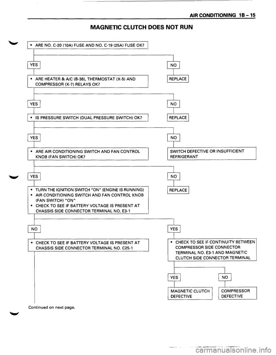
MAGNETIC CLUTCH DOES NOT RUN
• ARE NO. C-20 (10A) FUSE AND NO. C-19 (25A) FUSE OK?
•
ARE HEATER & A!C (B-36), THERMOSTAT (X-5) AND
COMPRESSOR (X-7) RELAYS OK?
•
ARE AIR CONDITIONING SWITCH AND FAN CONTROL
KNOB
(FAN SWITCH) OK?
•
TURN THE IGNITION SWITCH "ON" (ENGINE IS RUNNING)
• AIR CONDITIONING SWITCH
AND FAN CONTROL KNOB
(FAN SWITCH) "ON"
• CHECK TO SEE IF BATTERY VOLTAGE IS PRESENT AT
CHASSIS SIDE CONNECTOR TERMINAL NO. E3-1
• CHECK TO SEE IF BATTERY VOLTAGE IS PRESENT AT
CHASSIS SIDE CONNECTOR TERMINAL NO. C25-1
Continued on next page.
SWITCH DEFECTIVE OR INSUFFICIENT
REFRIGERANT
• CHECK TO
SEE IF CONTINUITY BETWEEN
COMPRESSOR SIDE CONNECTOR
TERMINAL NO.
E3-1 AND MAGNETIC
CLUTCH SIDE CONNECTOR TERMINAL
Page 73 of 1928
AIR CONDITIONING 1 B -19
ON-VEHICLE SERVICE
GENERAL REPAIR PROCEDURE
Precautions for Replacement or Repair of Air
Conditioning Parts
There are certain procedures, practices and pre
cautions
that should be followed when servicing air
conditioning systems:
• Keep your work area clean.
•
Always wear safety goggle and protective gloves
when working on refrigerant systems.
• Beware of the danger of carbon monoxide fumes
caused by running the engine.
• Beware of discharged refrigerant in enclosed or
improperly ventilated garages.
• Always disconnect the negative battery cable and
discharge and recover the refrigerant
whenever
repairing the air conditioning system.
• When discharging and recovering the refrigerant,
do not allow refrigerant to discharge too fast; it
will draw compressor oil out of the system.
• Keep moisture and contaminants out of the sys
tem.
When disconnecting or removing any lines
or parts, use plugs or caps to close the fittings
immediately.
Never remove the caps or plugs until the lines or
parts are reconnected or installed.
•
When disconnecting or reconnecting the lines,
use
two wrenches to support the line fitting, to
prevent from twisting or other damage.
• Always install new 0-rings whenever a connec
tion is disassembled.
• Before connecting any hoses or lines, apply new
specified compressor oil to the 0-rings.
• When removing and replacing any parts which
require discharging the refrigerant circuit, the
operations described in
this section must be per
formed in the following sequence:
1. Use the J-39500 (ACR4
: HFC-134a Refrigerant
Recovery/Recycling/Recharging/System)
or
equivalent to thoroughly discharge and re
cover
the refrigerant.
2. Remove and replace the defective part.
3.
After evacuation, charge the air conditioning
system and check for leaks.
Repair of Refrigerant Leaks
Refrigerant Line Connections
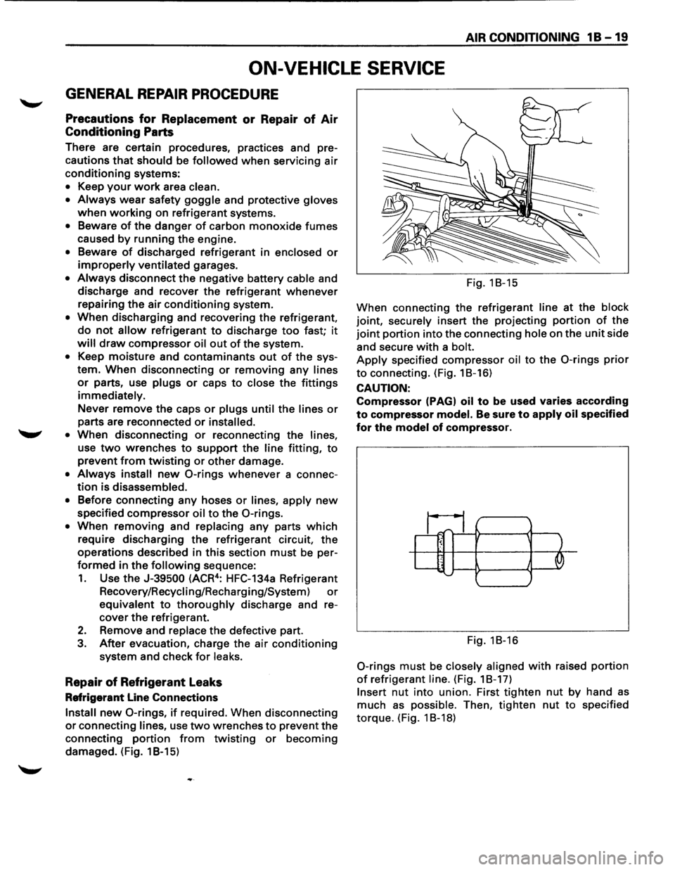
Install new 0-rings, if required. When disconnecting
or connecting lines, use two wrenches to prevent the
connecting
portion from twisting or becoming
damaged. (Fig. 1 B-15) Fig.
18-15
When connecting the refrigerant
line at the block
joint, securely insert the projecting portion of the
joint portion into the connecting hole on the unit side
and secure
with a bolt.
Apply specified compressor oil to the 0-rings prior
to connecting. (Fig. 18-16)
CAUTION:
Compressor (PAGI oil to be used varies according
to compressor model. Be sure to apply oil specified
for the model of compressor.
~1;1_ ~ ' .. J '--......
Fig. 18-16
0-rings must be closely aligned with raised portion
of refrigerant line. (Fig. 18-17)
Insert nut into union. First tighten nut by hand as
much as possible. Then, tighten nut to specified
torque. (Fig. 1 8-18)
Page 77 of 1928
6.
7.
Perform system leak test.
• Charge the system with approx. 200 g (0.44
lbs) of HFC-134a.
• Make sure the high pressure valve of the
manifold gauge is closed.
• Check
to ensure that the degree of pressure
does
not change.
• Check for refrigerant leaks by using a HFC-
134a leak detector.
• If a leak occurs, recover the refrigerant. Repair
the leak, and start all over again from the first
step of evacuation.
If no leaks are found, continue charging re
frigerant to the air conditioning system.
• Charge the refrigerant until the scale reading
decreases
by the amount of the charge
specified.
Specified
amount g (lbs.) I 750 (1.65)
• If charging the system becomes difficult:
( 1) Run the engine at idle and close all the
vehicle doors.
(2) Turn A!C switch "ON".
(3) Set the fan switch to its highest position.
(4) Set air source selector lever to "CIRC".
(5) Slowly open the low side valve on the
manifold gauge set.
WARNING: BE ABSOLUTELY SURE NOT TO
OPEN THE HIGH PRESSURE VALVE OF THE
MANIFOLD GAUGE. SHOULD THE HIGH
PRESSURE VALVE BE OPENED, THE HIGH
PRESSURE REFRIGERANT WOULD FLOW
BACKWARD, AND
THIS MAY CAUSE THE
REFRIGERANT CONTAINER TO BURST.
8. When finished with the refrigerant charging,
close the low pressure valve of the manifold
gauge and container valve.
9. Check for refrigerant leaks.
AIR CONDITIONING 18 -23
Checking
the A/C system
1. Run the engine and close all the vehicle doors.
2. Turn A!C switch "ON", set the fan switch to its
highest position, set air source
lever to "CIRD"
and set temperature lever to full cool position.
3. Check the high and low pressure of the manifold
gauge.
• Immediately after charging refrigerant, both
high and low pressure are slightly high, but
they settle down to the pressure guidelines
shown below:
Ambient temperature: 25-30°C (77 -86°F)
Pressure guidelines:
• High-pressure side;
Approx. 1372.9-1863.3kPa (199.1-270.2psi)
• Low-pressure side;
Approx. 147.1-294.2 kPa (21.3-42.7 psi)
• If an abnormal pressure is found, refer to
"CHECKING REFRIGERANT SYSTEM WITH
MANIFOLD
GAUGE" in this section.
4. Put your hand in front of the air outlet and move
the temperature control lever of the control
panel
to different positions. Check if the outlet
temperature changes as selected by the control
knob.
Page 92 of 1928
1 D-4 COMPRESSOR OVERHAUL
6. Perform oil return operation.
7. Remove the compressor and recheck the
amount of oil.
8. Adjust the compressor oil, if necessary.
Collected Amount
more than 90cc
(3.0
fl.oz.)
Charging Amount
same as collected amount
less than 90cc (3.0 fl.oz.) 90cc (3.0 fl.oz.)
Checking and Adjusting for Compressor
Replacement
150cc (5.0 fl.oz.) of oil is charged in compressor
(service parts).
So it is necessary to drain the
proper
amount of oil from the new compressor.
1. Perform oil return operation.
2. Discharge and recover refrigerant and remove
the compressor.
3. Drain the compressor oil and measure the
extracted
oil.
4. Check the compressor oil for contamination.
5. Adjust oil level as required.
Amount of oil drained
from used compressor
less than 90cc
(3.0
fl.oz.)
Draining amount of oil
from new compressor
Same as drained
amount
more than 90cc (3.0 fl.oz.) 90cc (3.0 fl.oz.)
6. Evacuate, charge and perform oil return oper
ation.
7. Check system operation.
CONTAMINATION OF COMPRESSOR OIL
Unlike engine oil, no cleaning agent is added to the
compressor
oil. Even if the compressor runs for a
long period
of time (approximately 1 season), the
oil never becomes contaminated as long
as there is
nothing
wrong with the compressor or its method
of use.
Inspect the extracted oil for any of the following
conditions:
• The capacity of the oil has increased.
• The oil has changed color to red.
• Foreign substances, metal powder, etc., are
present in the oil.
If any of these conditions exists, compressor oil
is contaminated. Whenever contaminated com
pressor
oil is discovered, the receiver/dryer must
be
replaced.
OIL RETURN OPERATION
There is close affinity between the oil and the
refrigerant. During normal operation, part
of the oil
recirculates
with the refrigerant in the system.
When checking the
amount of oil in the system, or
replacing any component of the system, the com
pressor
must be run in advance for oil return oper
ation. The procedure is as
follows:
1. Open the all doors and engine hood.
2. Start the engine and air conditioning switch is
"ON" and Set the fan control knob at its hig
hest position.
3. Run the compressor for more than 20 minutes
between
800 and 1,000 rpm in order to operate
the system.
4. Stop the engine.
REPLACEMENT OF COMPONENT PARTS
When replacing system component parts, supply
the following
amount of oil to the component parts
to be installed.
Component parts to be installed Amount of oil
Evaporator 50cc
(1.7
fl.oz.)
Condenser 30cc
(1.0 fl.oz.)
Receiver/dryer 30cc
(1.0 fl.oz.)
Refrigerant line (one piece) 1 Occ (0.3 fl. oz.)
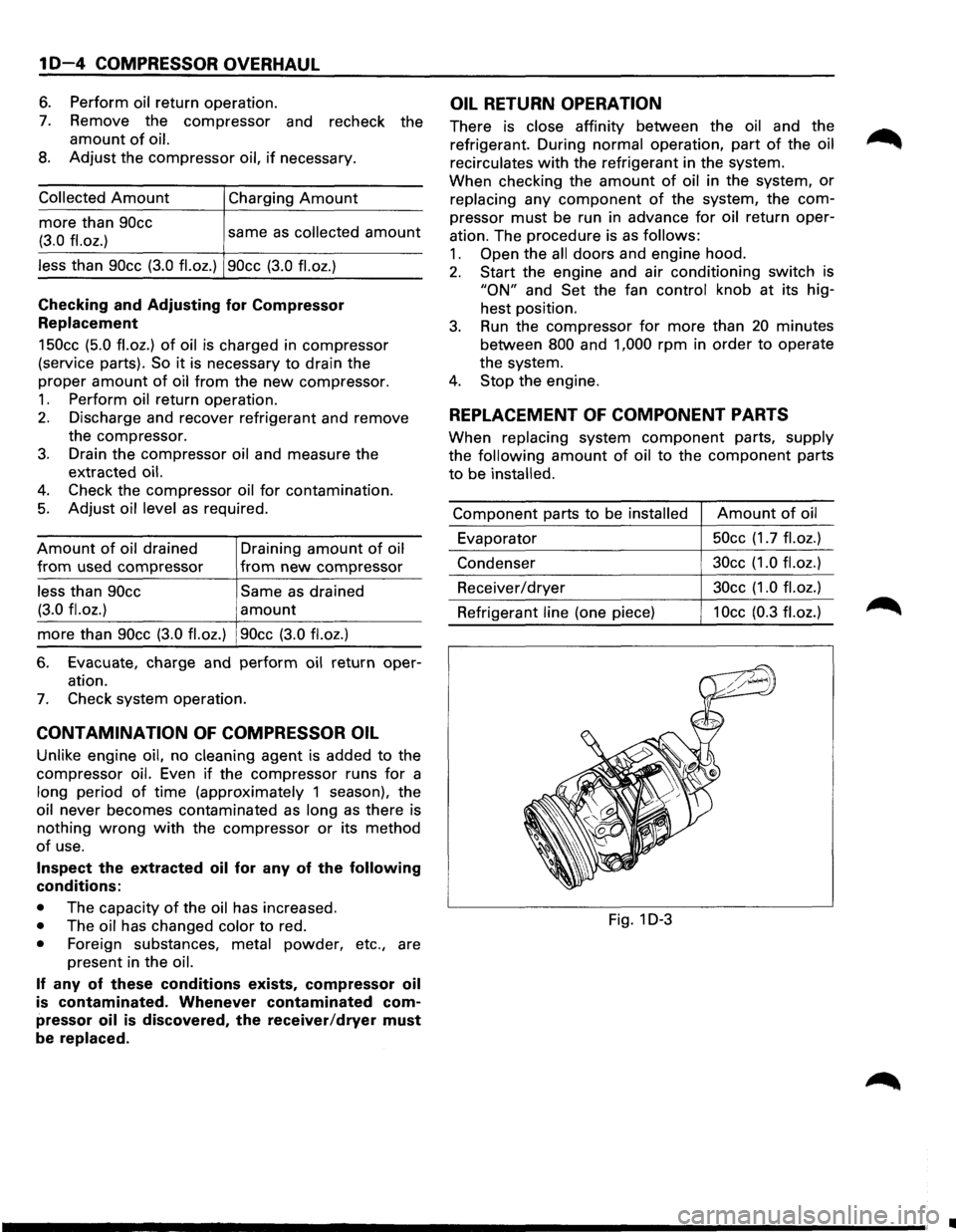
Fig. 1 D-3
•
Page 111 of 1928
1••1 REMOVAL (Fig. 2C-1)
Preparation: • Open the hood.
'-"' • Support the hood.
1. Front wiper arms
• Refer to "Front wiper removal" in section 8.
2. Cowl cover brackets
• Disconnect two screws each side.
3. Cowl cover
• Disconnect three screws.
4. Cowl cover seals
5. Front window lower molding
6. Cowl cover stoppers
I•• I INSTALLATION
To install, follow the removal steps in reverse order.
ENGINE HOOD
1••1 REMOVAL
Preparation: • Open the hood.
• Support the hood.
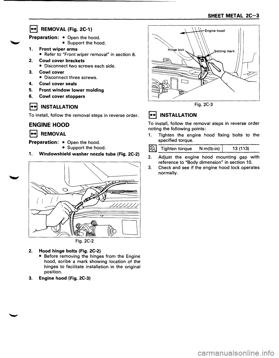
1. Windowshield washer nozzle tube (Fig. 2C-2)
( f
0
Fig. 2C-2
2. Hood hinge bolts (Fig. 2C-2)
• Before removing the hinges from the Engine
hood, scribe a mark showing
location of the
hinges
to facilitate installation in the original
position.
3. Engine hood (Fig. 2C-3)
SHEET METAL 2C-3
Fig. 2C-3
1••1 INSTALLATION
To install, follow the removal steps in reverse order
noting the following points:
1. Tighten the engine hood fixing bolts to the
specified torque.
1~1 Tighten torque N·m(lb·in) I 13 (113)
2. Adjust the engine hood mounting gap with
reference to "Body dimension" in section 10.
3. Check and see if the engine hood lock operates
normally.
Page 113 of 1928
ENGINE HOOD LOCK
5
2
4
SHEET METAL 2C-5
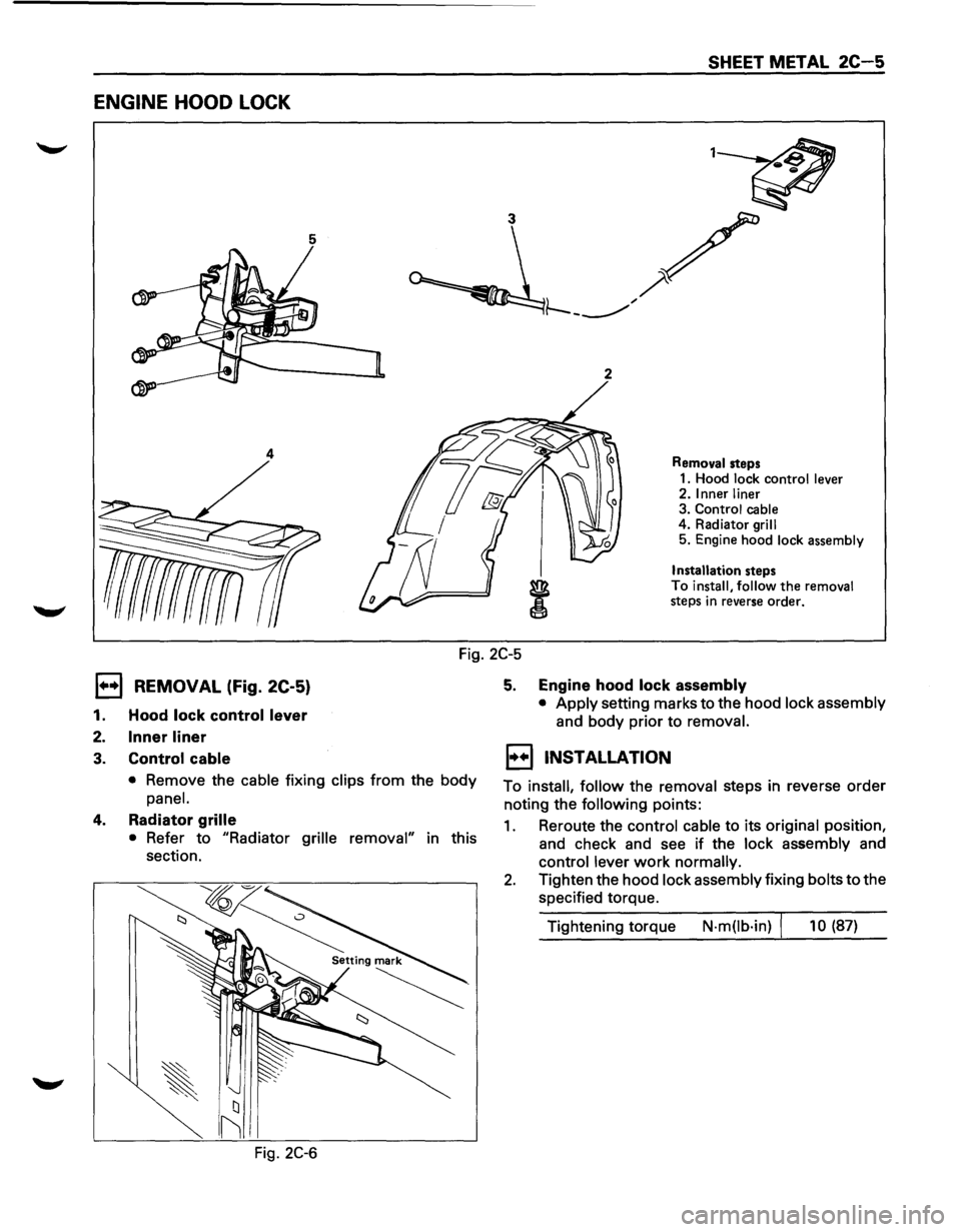
Removal steps
1. Hood lock control lever
2. Inner liner
3. Control cable
4. Radiator
grill
5. Engine hood lock assembly
Installation steps
To install, follow the removal
steps in reverse order.
Fig. 2C-5
1••1 REMOVAL (Fig. 2C-5)
1. Hood lock control lever
2. Inner liner
3. Control cable
• Remove the cable fixing clips from the body
panel.
4. Radiator grille
• Refer to "Radiator grille removal" in this
section.
Fig.
2C-6
5. Engine hood lock assembly
• Apply setting marks to the hood lock assembly
and body prior to removal.
EJ INSTALLATION
To install, follow the removal steps in reverse order
noting the
following points:
1. Reroute the control cable to its original position,
and check and see if the
lock assembly and
control lever work normally.
2. Tighten the hood lock assembly fixing bolts to the
specified torque.
Tightening torque
N·m(lb·in) I 10 (87)
Page 141 of 1928
POWER STEERING SYSTEM TEST
TEST PROCEDURE
Test of fluid pressure in the power steering system is
performed to determine whether
or not the oil pump
and
power steering unit are functioning normally.
The power steering system test is method used to
identify and
isolate hydraulic circuit difficulties. Prior
to performing this test, the following inspections and
corrections,
if necessary, must be made.
[!) INSPECT
• Pump reservoir for proper fluid level.
•
Pump belt for proper tension.
• Pump driver pulley condition.
1. Place a container under the pump to catch the
fluid when disconnecting or connecting the
hoses.
2. With the engine NOT running, disconnect the
pressure hose
at the power steering pump and
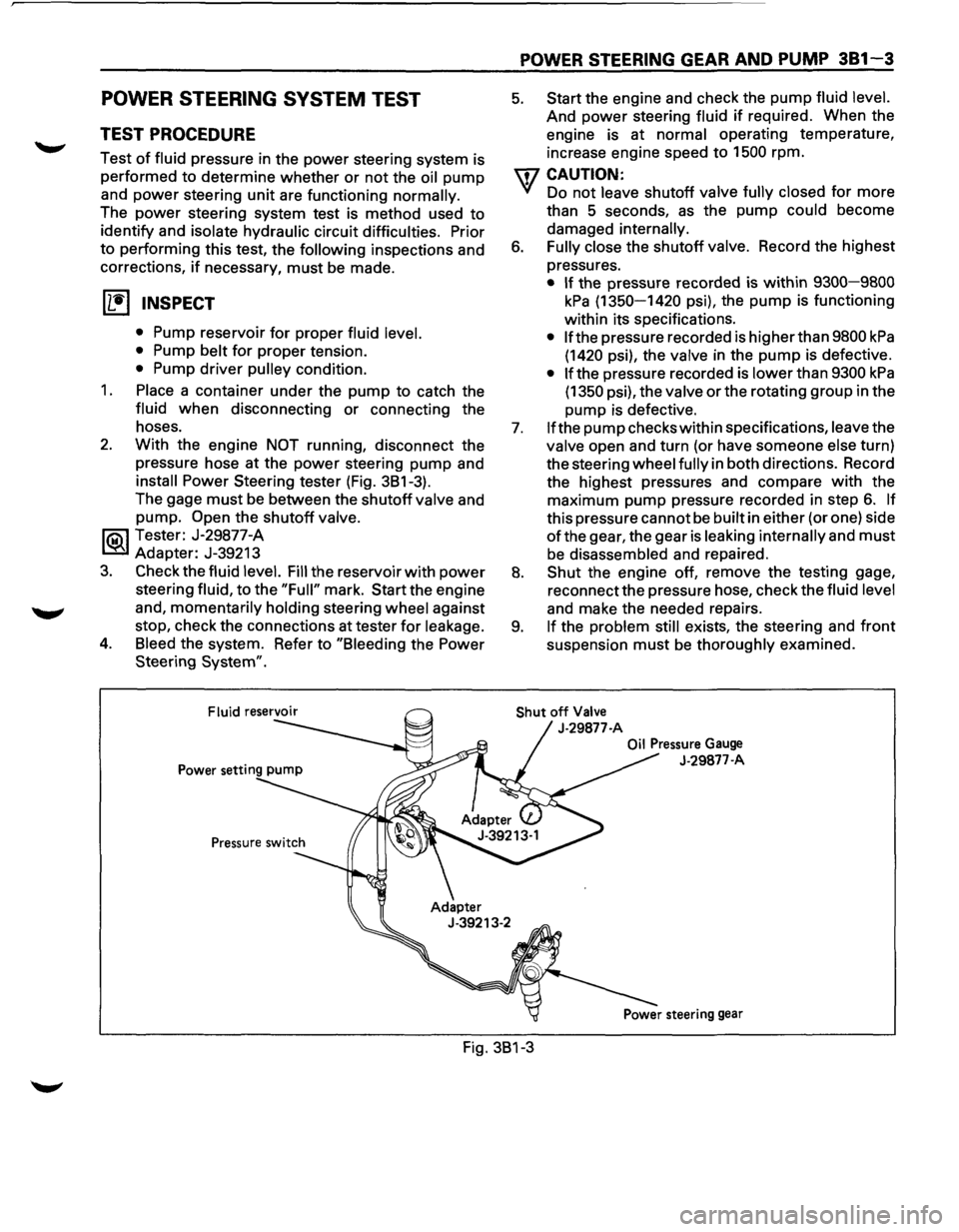
install Power Steering tester (Fig. 3B1-3).
The gage
must be between the shutoff valve and
pump.
Open the shutoff valve.
li5\l Tester: J-29877-A
~ Adapter: J-39213
3. Check the fluid level. Fill the reservoir with power
steering fluid, to the "Full" mark. Start the engine
and,
momentarily holding steering wheel against
stop, check the connections at tester
for leakage.
4. Bleed the system. Refer to "Bleeding the Power
Steering
System".
POWER STEERING GEAR AND PUMP 381-3
5. Start the engine and check the pump fluid level.
And power steering fluid if required. When the
engine is at
normal operating temperature,
increase engine speed to 1500 rpm.
U7 CAUTION:
VI Do not leave shutoff valve fully closed for more
than 5 seconds,
as the pump could become
damaged
internally.
6. Fully close the shutoff valve. Record the highest
pressures.
• If the pressure recorded is within 9300-9800
kPa (1350-1420 psi), the pump is functioning
within its specifications.
• If the pressure recorded is higher than 9800 kPa
(1420 psi), the valve in the pump is defective.
• If the pressure recorded is lower than 9300 kPa
(1350 psi), the valve or the rotating group in the
pump is defective.
7. If the pump checks within specifications, leave the
valve open and turn (or have someone else turn)
the steering
wheel fully in both directions. Record
the highest pressures and compare
with the
maximum pump pressure recorded in step
6. If
this pressure cannot be built in either (or one) side
ofthe gear, the gear is leaking internally and must
be disassembled and repaired.
8. Shut the engine off, remove the testing gage,
reconnect the pressure hose, check the
fluid level
and make the needed repairs.
9. If the problem still exists, the steering and front
suspension must be thoroughly examined.
Shut off Valve
J-29877-A
Oil Pressure Gauge
J-29877-A
Fig. 3B1-3
Page 142 of 1928
381 - 4 POWER STEERING GEAR AND PUMP
ON-VEHICLE SERVICE
MAINTENANCE
The hydraulic system should be kept clean and fluid
level in the reservoir should be checked at regular
intervals
and fluid added when required. Refer to
"MAINTENANCE AND LUBRICATION" in section OB
ofthe manual for type offluid to be used and intervals
for filling.
If the system contains some dirt, flush it as detailed
later
in this section. If it is exceptionally dirty, both the
pump and the gear must be completely disassembled
before further usage.
All tubes, hoses, and fittings should be inspected for
leakage at regular intervals. Fittings must be tight.
Make sure the clips, clamps and supporting tubes and
hoses are in
place and properly secured.
Power steering hoses and lines must not be twisted,
kinked or tightly bent. Air in the system will cause
spongy action and noisy operation. When a hose is
disconnected
or when fluid is lost, for any reason, the
system must be bled after refilling. Refer to "Bleeding
the Power Steering System" in this section.
FLUID LEVEL
1. Run the engine until the power steering fluid
reaches normal operating temperature, about
55°C (130°F), then shut the engine off.
2. Check the level of fluid in the reservoir.
3. If the fluid level is low, add power steering fluid
as specified in "MAINTENANCE AND LUBRI
CATION" in Section OB to the proper level and
install the receiver cap.
4. When checking the fluid level after the steering
system has been serviced,
air must be bled from
the system. Refer to "Bleeding the Power
Steering
System" in this section.
BLEEDING THE POWER STEERING
SYSTEM
When a power steering pump or gear has been
installed, or an oil line has been disconnected, the air
that has entered the system must be bled out before
the vehicle is operated. If air is allowed to remain in
the power steering fluid system, noisy and
unsatisfactory operation of the system may result.
BLEEDING PROCEDURE
When bleeding the system, and any time fluid is
added
to the power steering system, be sure to use
only power steering fluid as specified in
"MAINTENANCE AND LUBRICATION" in section OB.
1. Fill the pump fluid reservoir to the proper level
and let the fluid settle for at least two minutes.
2. Start the engine and let it run for a few seconds.
Do
not turn the steering wheel. Then turn the
engine off.
3. Add fluid if necessary.
4. Repeat the above procedure until the fluid level
remains constant after running the engine.
5. Raise the front end of the vehicle so that the
wheels are off the ground.
6. Start the engine. Slowly turn the steering wheel
right and left, lightly contacting the wheel stops.
7. Add power steering fluid if necessary.
8. Lower the vehicle and turn the steering wheel
slowly from lock to lock.
9. Stop the engine. Check the fluid level and refill
as required.
10.
If the fluid is extremely foamy, allow the vehicle
to stand a few minutes and repeat the above
procedure.
~ INSPECT
• Belt for tightness.
• Pulley for looseness or damage. The pulley
should not wobble with the engine running.
• Hoses so they are not touching any other parts
of the vehicle.
• Fluid level
and fill to the proper level.
FLUSHING THE POWER STEERING
SYSTEM
1. Raise the front end of the vehicle off the ground
until the wheels are free to turn.
2. Remove the fluid return line at the pump inlet
connector and plug the connector port on the
pump.
Position the line toward a large container to
catch the draining fluid.
3. While running the engine at idle, fill the reservoir
with new power steering fluid. Turn the steering
wheel in both directions. DO NOT contact wheel
stops or hold the wheel in a corner, or fluid will
stop and the pump will be in pressure relief mode.
A sudden
overflow from the reservoir may
develop if the wheel is held at a stop.
4. Install all the lines and hoses. Fill the system with
new power steering fluid and bleed the system
as described in "Bleeding The Power Steering
System". Operate the engine for about 15
minutes.
Remove the
pump return line at the pump inlet
and plug the connection on the pump. While
refilling the reservoir, check the draining fluid for
contamination. If foreign material is still evident,
replace all lines, disassemble and clean or replace
the power steering system components. Do not
re-use any drained power steering fluid.
~
~
Page 143 of 1928
STEERING WHEEL FREE PLAY ADJUST
MENT
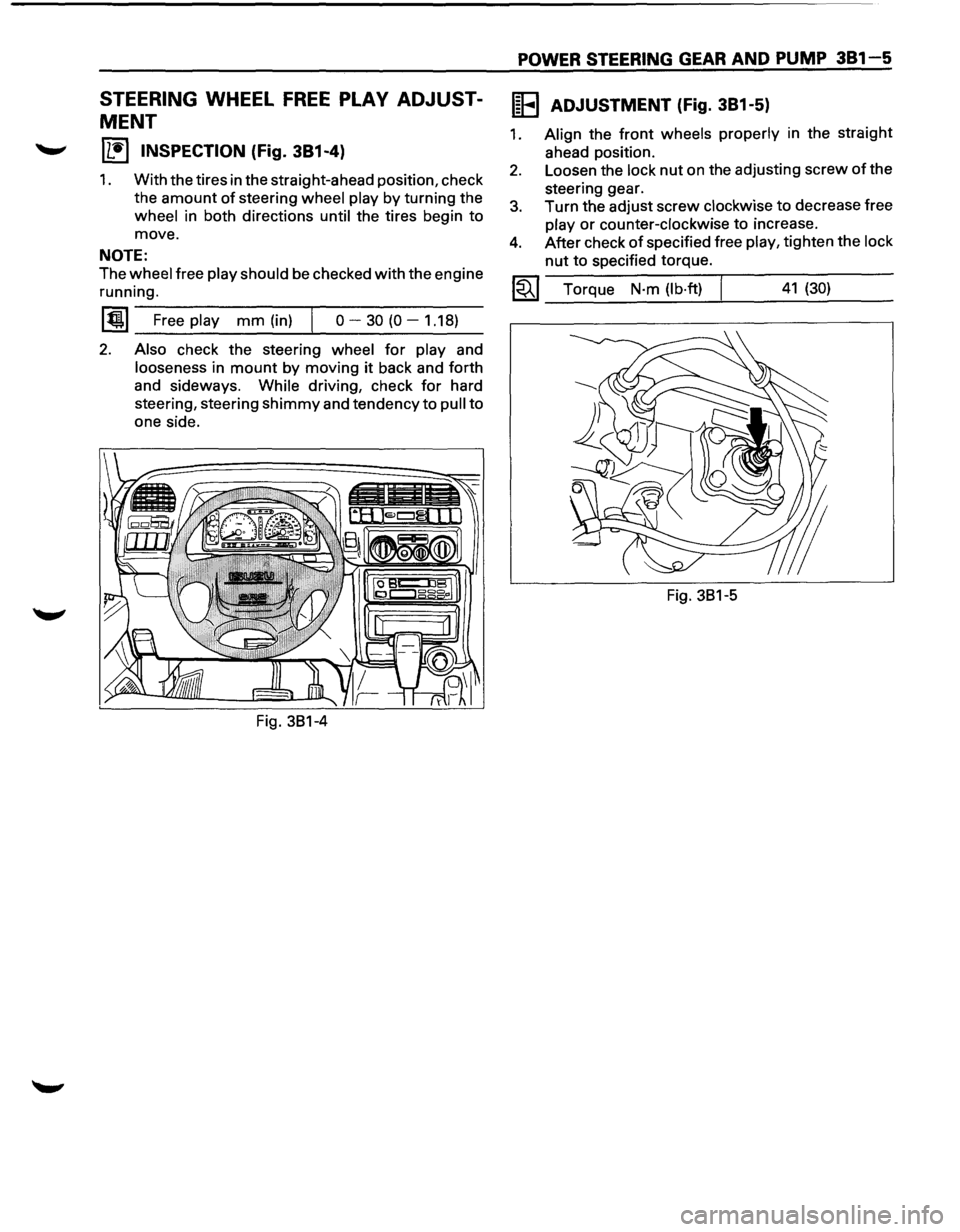
IL•I INSPECTION (Fig. 381-4)
1. With the tires in the straight-ahead position, check
the
amount of steering wheel play by turning the
wheel in both directions until the tires begin to
move.
NOTE:
The wheel free play should be checked with the engine
running.
~~~~F-r-ee--pl-ay---m-m--(in_)_,j--o----3-0-(0----1-.1-8~)-
2. Also check the steering wheel for play and
looseness in mount by moving it back and forth
and sideways.
While driving, check for hard
steering, steering
shimmy and tendency to pull to
one side.
POWER STEERING GEAR AND PUMP 381-5
IEEI ADJUSTMENT (Fig. 381-5)
1. Align the front wheels properly in the straight
ahead position.
2. Loosen the lock nut on the adjusting screw of the
steering gear.
3. Turn the adjust screw clockwise to decrease free
play or counter-clockwise to incre~se.
4. After check of specified free play, t1ghten the lock
nut to specified torque.
~~~ Torque N·m (lb·ft) I 41 (30)
Fig. 381-5