fuse chart ISUZU TROOPER 1995 Service Manual
[x] Cancel search | Manufacturer: ISUZU, Model Year: 1995, Model line: TROOPER, Model: ISUZU TROOPER 1995Pages: 1928
Page 1448 of 1928
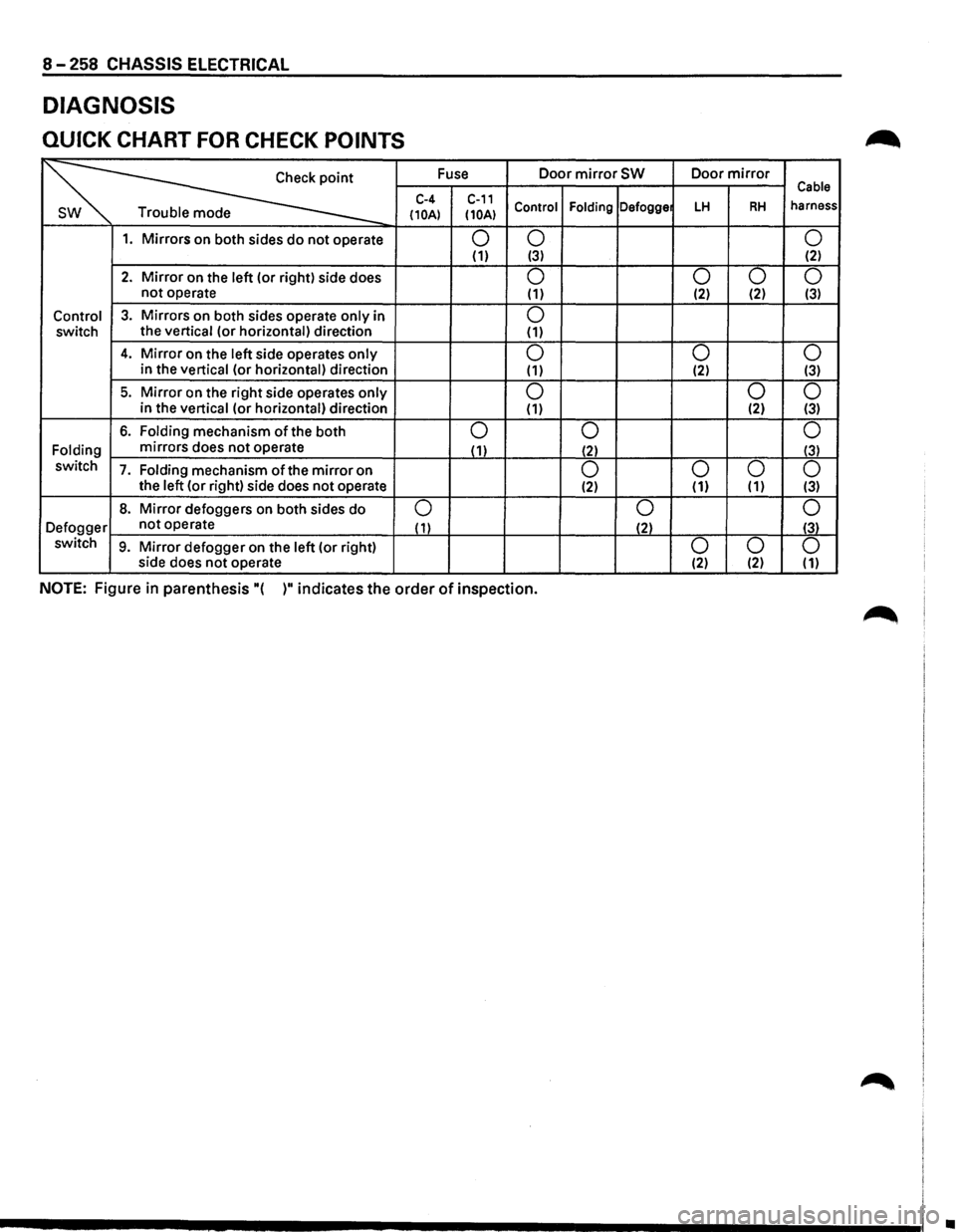
8 -258 CHASSIS ELECTRICAL
DIAGNOSIS
QUICK CHART FOR CHECK POINTS
~
Fuse Door mirror SW Door mirror Cable C-4 C-11 Control Folding Defogge LH RH harness Trouble mode (10A) (10A)
1. Mirrors on both sides do not operate 0 0
0 (1) (3) (2)
2. Mirror on the left (or right) side does 0 0 0 0 not operate (1) (2) (2) (3)
Control 3. Mirrors on both sides operate only in 0 switch the vertical
(or horizontal) direction (1)
4. Mirror on the left side operates only 0 0 0 in
the vertical (or horizontal) direction (1) (2) (3)
5. Mirror on
the right side operates only 0 0 0 in the vertical (or horizontal) direction (1) (2) (3)
6. Folding
mechanism of the both 0 0 0
Folding mirrors
does not operate (1)
(2) (3)
switch 7. Folding mechanism ofthe mirror on 0 0
0
0 the left (or right) side does not operate (2) (1) (1) (3)
8. Mirror defoggers
on both sides do 0 0
0
Defogger not
operate ( 1) (2) (3)
switch 9. Mirror defogger on the left (or right) 0 0
0 side does not operate (2) (2) (1)
NOTE: Figure in parenthesis "( )" indicates the order of inspection.
•
Page 1540 of 1928
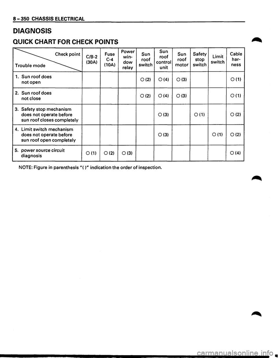
8 -350 CHASSIS ELECTRICAL
DIAGNOSIS
QUICK CHART FOR CHECK POINTS
~
Fuse Power Sun Sun
Sun Safety Cable
C/B-2 win-roof Limit
(30A) C-4 dow roof control roof stop switch har-
(10A) relay switch unit motor switch
ness T
1. Sun roof does 0 (2) 0 (4) 0 (3) 0 (1) not open
2. Sun roof does 0 (2) 0 (4) 0 (3) 0 (1) not close
3. Safety stop
mechanism
does
not operate before 0(3) 0 (1) 0 (2)
sun roof closes completely
4. Limit switch mechanism
does
not operate before 0 (3) 0 (1) 0 (2)
sun roof open completely
5. power source circuit 0 (1) 0 (2) 0 (3) 0 (4)
diagnosis
NOTE: Figure in parenthesis
"( )" indication the order of inspection.
Ill
Page 1568 of 1928
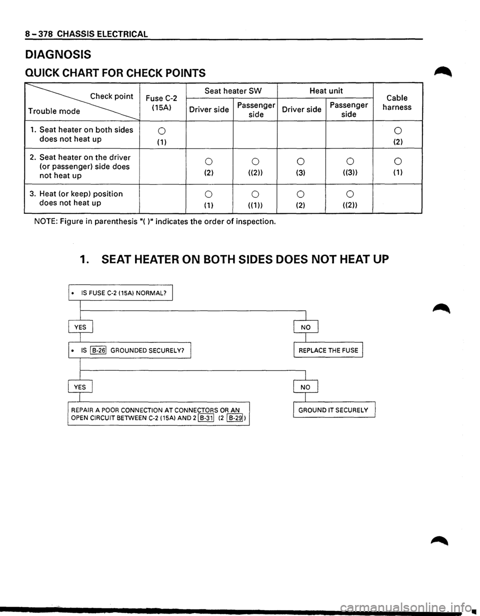
8-378 CHASSIS ELECTRICAL
DIAGNOSIS
QUICK CHART FOR CHECK POINTS
~
Seat heater SW Heat unit Fuse C-2 Cable
(15A)
Driver side Passenger
Driver side Passenger
harness
e side side
1. Seat heater
on both sides 0 0 does not heat
up (1) (2)
2. Seat heater on the driver 0 0 0 0 0 (or
passenger) side does
not heat up (2) ((2)) (3) ((3))
( 1)
3. Heat (or keep) position 0 0 0 0 does
not heat up
( 1) ( ( 1)) (2) ((2))
NOTE: Figure in parenthesis "( )" indicates the order of inspection.
1. SEAT HEATER ON BOTH SIDES DOES NOT HEAT UP
• IS FUSE C-2 (15A) NORMAL? I
I
I
YES I
l
• IS ~ GROUNDED SECURELY? I
l
l
YES I
I
REPAIR A POOR CONNECTION AT CONNECTORS OR AN
OPEN CIRCUIT BETWEEN C-2 (15A) AND 21 B-311 (2 I B-291)
I
I NO I
I
l REPLACE THE FUSE I
I
I NO I
I
l GROUND IT SECURELY J
Page 1592 of 1928
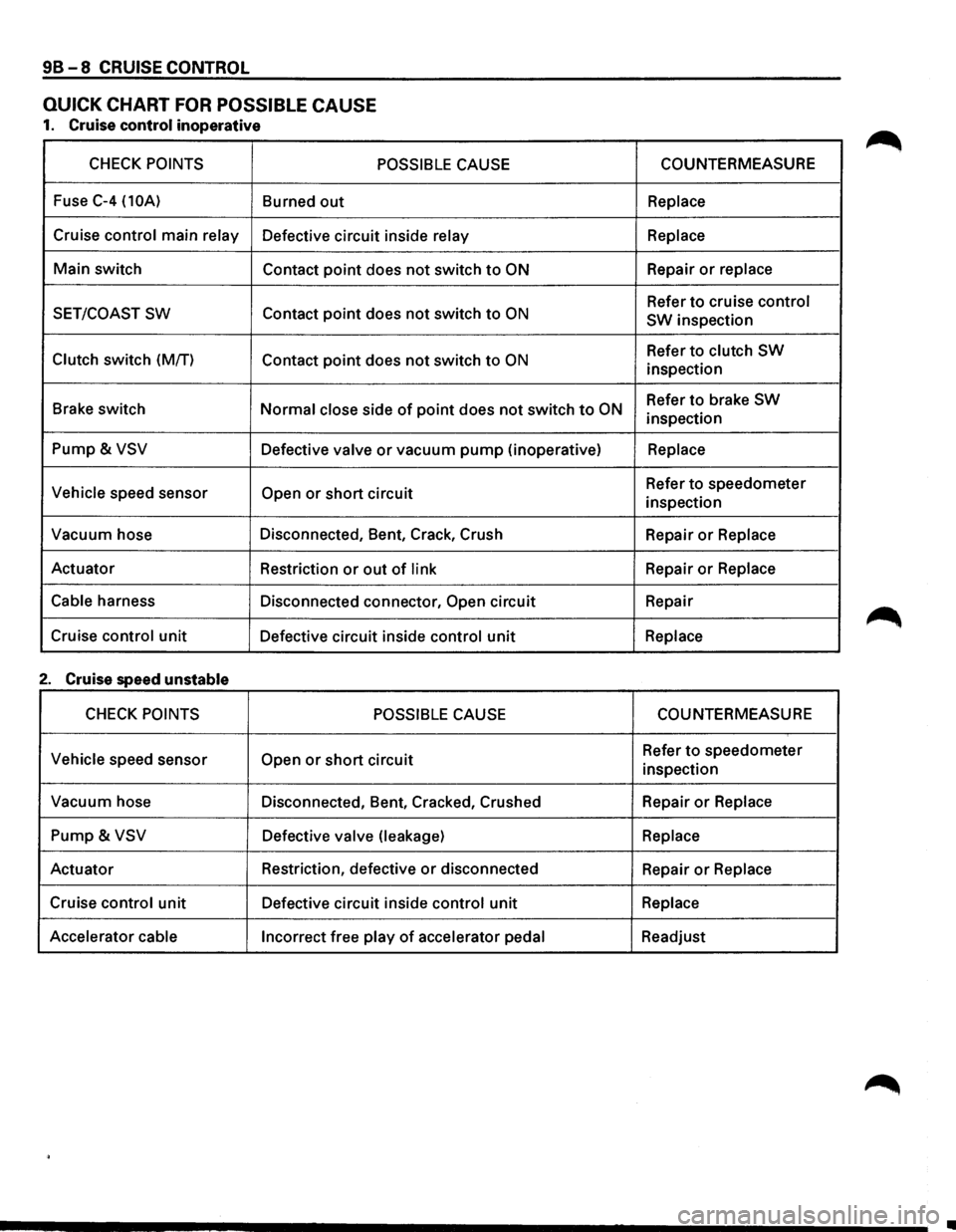
98-8 CRUISE CONTROL
QUICK CHART FOR POSSIBLE CAUSE
1. Cruise control inoperative
CHECK POINTS POSSIBLE CAUSE
Fuse C-4 (10A) Burned out
Cruise control main relay Defective circuit inside relay
Main switch
Contact point does not switch to ON
SET/COAST SW Contact point does not switch to ON
Clutch switch (M/T)
Contact point does not switch to ON
Brake switch Normal close side of point does not switch to ON
Pump & VSV Defective valve or vacuum pump (inoperative)
Vehicle speed sensor Open or short circuit
Vacuum hose Disconnected, Bent, Crack, Crush
Actuator Restriction
or out of link
Cable
harness Disconnected connector, Open circuit
Cruise
control unit Defective circuit inside control unit
2. Cruise speed unstable
CHECK POINTS POSSIBLE CAUSE
Vehicle
speed sensor Open or short circuit
Vacuum hose
Disconnected, Bent, Cracked, Crushed
Pump & VSV Defective valve (leakage)
Actuator Restriction,
defective or disconnected
Cruise
control unit Defective circuit inside control unit
Accelerator cable
Incorrect free play of accelerator pedal COUNTERMEASURE
Replace
Replace
Repair or replace
Refer to cruise control
SW
inspection
Refer
to clutch SW
inspection
Refer
to brake SW
inspection
Replace
Refer to speedometer
inspection
Repair
or Replace
Repair or Replace
Repair
Replace
COUNTERMEASURE
Refer to speedometer
inspection
Repair
or Replace
Replace
Repair or Replace
Replace
Readjust
•
Page 1595 of 1928
CRUISE CONTROL 98-11
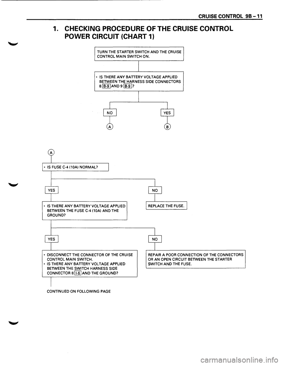
1. CHECKING PROCEDURE OF THE CRUISE CONTROL
POWER CIRCUIT
(CHART 1)
TURN THE STARTER SWITCH AND THE CRUISE
CONTROL MAIN SWITCH ON.
• IS THERE ANY BATTERY VOLTAGE APPLIED BETWEEN THE HARNESS SIDE CONNECTORS
sl B-9IAND 9IB-91?
• IS THERE ANY BATTERY VOLTAGE APPLIED
BETWEEN THE FUSE C-4 (10Al AND THE
GROUND?
• DISCONNECT THE CONNECTOR OF THE CRUISE
CONTROL MAIN SWITCH.
• IS THERE ANY BATTERY VOLTAGE APPLIED
BETWEEN THE SWITCH HARNESS SIDE
CONNECTOR a [I§] AND THE GROUND?
CONTINUED ON FOLLOWING PAGE
REPAIR A POOR CONNECTION OF THE CONNECTORS OR AN OPEN CIRCUIT BETWEEN THE STARTER
SWITCH
AND THE FUSE.
Page 1611 of 1928
CRUISE CONTROL 9B-27
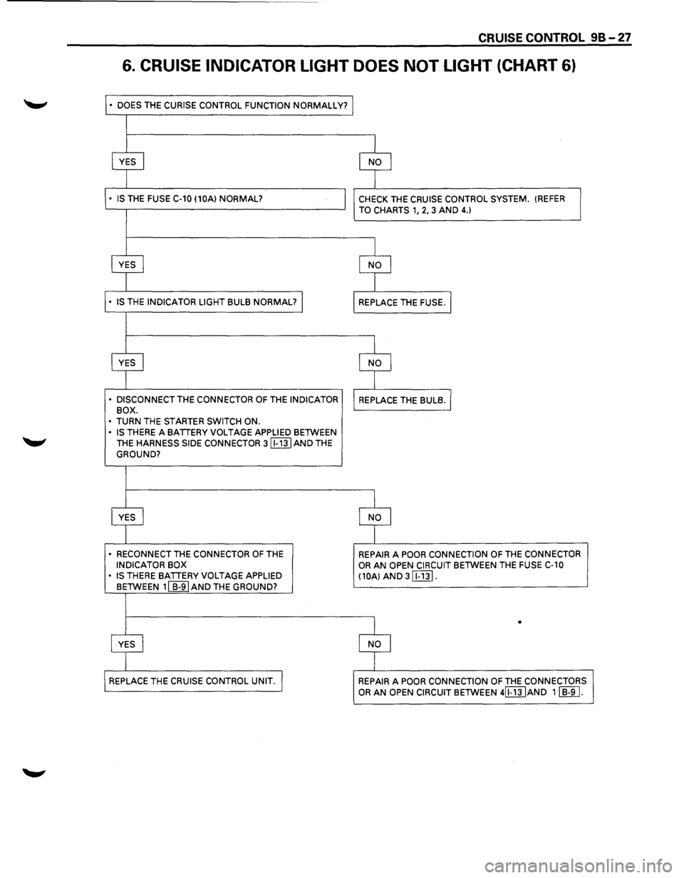
6. CRUISE INDICATOR LIGHT DOES NOT LIGHT (CHART 6)
• DOES THE CURISE CONTROL FUNCTION NORMALLY?
• DISCONNECT THE CONNECTOR OF THE INDICATOR
BOX.
•
TURN THE STARTER SWITCH ON.
• IS THERE A BATIERY VOLTAGE APPLIED BETWEEN
THE
HARNESS SIDE CONNECTOR 3 (EIT] AND THE
GROUND?
• RECONNECT THE CONNECTOR OF THE INDICATOR BOX
• IS THERE BATIERY VOLTAGE APPLIED
BETWEEN 11 B-91 AND THE GROUND?
CHECK THE CRUISE CONTROL SYSTEM. (REFER
TO CHARTS 1, 2, 3 AND 4.)
REPAIR A POOR CONNECTION OF THE CONNECTOR OR AN OPEN CIRCUIT BETWEEN THE FUSE C-10
(10A) AND 3 [Ej1].
•
REPAIR A POOR CONNECTION OF THE CONNECTORS
OR AN OPEN CIRCUIT BETWEEN 4[f"j]JAND 11 B-9 I.
Page 1637 of 1928
Supplemental Restraint System 9J-13
ON-VEHICLE SERVICE
SERVICE PRECAUTIONS
WARNING: WHEN PERFORMING SERVICE ON OR
AROUND SRS COMPONENTS OR SRS WIRING,
FOLLOW
THE PROCEDURES LISTED BELOW TO
TEMPORARILY DISABLE THE SRS. FAILURE TO
FOLLOW PROCEDURES COULD RESULT IN
POSSIBLE AIR
BAG DEPLOYMENT, PERSONAL
INJURY OR OTHERWISE
UNNEEDED SRS
REPAIRS.
The DERM in Driver-Passenger SRS can maintain
sufficient voltage to cause a deployment for up to 2
minutes after the ignition switch is turned
"OFF," the
battery is disconnected, or the fuse powering the DERM
is removed.
Many of the service procedures require removal of the
"AIR BAG" fuse, and disconnection of the inflator
modules from the deployment loop to avoid an accidental
deployment.
If the inflator module is disconnected from
the deployment loop as noted in the "Disabling the
SRS"
procedure that follows, service can begin immediately
without waiting for the 2-minute time period to expire.
DISABLING THE SRS
REMOVAL
Turn the ignition switch to "OFF"
1. Remove SRS fuse C-21, C-22, C-23 and C-24 from
left dash side lower fuse block.
2. Disconnect yellow 3-way connector at the base of
steering column.
3. Remove 1/P compartment door assembly, Refer to
"Passenger inflator module replacement" in section
9J-132.
4. Disconnect yellow 4-way connector behind the 1/P
compartment door assembly.
IMPORTANT
• With the "AIR BAG" fuse removed and ignition switch
"ON," if Fuse 21 left. the "AIR BAG" warning lamp will
be "ON." This is normal operation and does not
indicate an
SRS malfunction.
ENABLING THE SRS
INSTALLATION
Turn ignition switch to "LOCK" and remove key.
1. Connect yellow 4-way connector for passenger
inflator module.
2. 1/P compartment door assembly, Refer to
"Passenger inflator module replacemenf' in section
9J-3.
3. Connect yellow 2-way connector at the base of the
steering column.
4. Install "AIR BAG" fuse C-21, C-22, C-23 and C-24 to
left dash side lower fuse block.
Turn ignition switch to
"RUN" and verify that the "AIR
BAG"
warning lamp flashes seven times and then turns
"OFP' If it does not operate as described, perform the
"SRS Diagnostic System Check" in section 9J-2.
HANDLING/INSTALLATION/DIAGNOSIS
1. Inflator modules should not be subjected to
temperatures above
65°C{150°F).
2. Discriminating sensors, inflator modules, arming
sensors, or DERMs should not be used if they have
been dropped from a height
of 91.4 centimeters
{3feet).
3. When a discriminating sensor or arming sensor is
replaced, it must be oriented with the arrow on the
sensor pointing toward the front of the vehicle.
It is
very important for the discriminating sensors and
arming sensor to be located flat on the mounting
surface, parallel to the vehicle datum line.
It is
important that the sensor mounting surface is free of
any dirt or other foreign material.
4. Do not apply power to the SRS unless all
components are connected or a diagnostic chart
requests it, as this
will set a diagnostic trouble code.
5. The "SRS Diagnostic System Check" must be the
starting point of any
SRS diagnostics. The "SRS
Diagnostic System Check" will verify proper "AIR
BAG"
warning lamp operation and will lead you to the
correct chart to diagnose any
SRS malfunctions.
Bypassing these procedures may result
in extended
diagnostic time, incorrect diagnosis, and incorrect
parts replacements.
Page 1656 of 1928
9J-32 Supplemental Restraint System (SRS)
SRS DIAGNOSTIC SYSTEM CHECK
WARNING: TO AVOID DEPLOYMENT WHEN
TROUBLESHOOTING THE SRS, DO NOT USE
ELECTRICAL TEST EQUIPMENT SUCH AS A
BATTERY-POWERED OR AC-POWERED
VOLTMETER, OHMMETER, ETC., OR ANY TYPE OF
ELECTRICAL EQUIPMENT OTHER THAN THAT
SPECIFIED IN THIS MANUAL. DO NOT USE A
NON-POWERED PROBE TYPE TESTER.
INSTRUCTIONS IN THIS MANUAL MUST BE
FOLLOWED CAREFULLY, OTHERWISE PERSONAL
INJURY
MAY RESULT.
The diagnostic procedures used in this section are
designed to find and repair
SRS malfunctions. To get the
best results, it is important to use the diagnostic charts
and
follow the sequence listed below:
A. PERFORM THE "SRS DIAGNOSTIC SYSTEM
CHECK."
The "SRS Diagnostic System Check" must be the
starting point of any
SRS diagnostics. The "SRS
Diagnostic System Check" checks for proper "AIR
BAG"
warning lamp operation, the ability of the
DERM to communicate through the
"Serial Data" line
and whether SRS diagnostic trouble codes exist.
B. REFER TO THE PROPER DIAGNOSTIC CHART
AS
DIRECTED BY THE SRS DIAGNOSTIC
SYSTEM CHECK."
The "SRS Diagnostic System Check" will lead you to
the correct chart to diagnose any
SRS malfunctions.
Bypassing these procedures may result
in extended
diagnostic time, incorrect diagnosis and incorrect
parts replacement.
C. REPEAT THE "SRS DIAGNOSTIC SYSTEM
CHECK" AFTER ANY REPAIR OR DIAGNOSTIC
PROCEDURES HAVE
BEEN PERFORMED.
Performing
the "SRS Diagnostic System Check"
after all repair or diagnostic procedures will ensure
that the repair has been made correctly and that no
other malfunctions exist.
CIRCUIT DESCRIPTION
When the ignition switch is first turned "ON,""Ignition 1"
voltage is applied from the "C-22·C-23" fuse to the
DERM at the
"Ignition 1" input terminals "A9" and "A10"
and from the "C-21" fuse to the DERM at the "Redundant
Indicator Ignition 1" input terminal "B2". The DERM
responds by flashing the
"AIR BAG" warning lamp seven
times while performing tests on the
SRS.When the
engine is being cranked,
"Starter'' voltage is applied from
the
"C-1" fuse to the DERM at the "Crank" input terminal
"B10".The DERM responds by grounding the "SRS
Indicator"
output terminal "B 1" until "Starter" voltage is
removed from the "Crank" input. This results in the "AIR
BAG" warning lamp being "ON" steady during
cranking.After cranking, the DERM will flash the "AIR
BAG"
warning lamp six times and perform tests on the
SRS.
NOTES ON SYSTEM CHECK CHART ~
1. The "AIR BAG" warning lamp should flash seven
times after ignition is first turned
"ON."
2. The "AIR BAG" warning lamp should remain "ON"
steady during cranking.
3. When the "AIR BAG" warning lamp flashes four
times during
"Bulb Check" this indicates a
malfunction
in the redundant lamp driver circuitry.
These malfunctions are diagnosed by
DTC 62 chart.
4. After cranking, the "AIR BAG" warning lamp should
flash six times then go
"OFF."
5. Improper operation of the "AIR BAG" warning lamp
is indicated. This test differentiates a warning lamp
stays
"ON" condition from a warning lamp does not
come
"ON" condition.
6. This test checks for the proper operation of the
"Serial Data" line. This test will also determine
whether history diagnostic trouble codes are stored
and, if so, identify them.
7. This test checks for proper operation of the
"Serial
Data"
line. This test will also identify the stored
diagnostic trouble codes and
whether they are
current or history.
~
DIAGNOSTIC AIDS
The order in which diagnostic trouble codes are
diagnosed is very important. Failure to diagnose the
diagnostic trouble codes in the order specified may result
in extended diagnostic time, incorrect diagnosis and
incorrect parts replacement.
Page 1658 of 1928
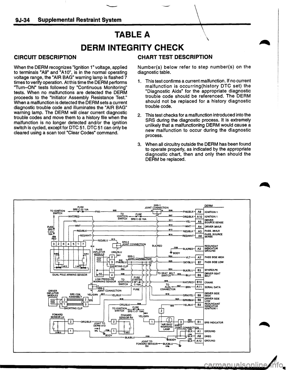
9J-34 Supplemental Restraint System
TABLE A
DERM INTEGRITY CHECK
CIRCUIT DESCRIPTION
When the DERM recognizes "Ignition 1" voltage, applied
to terminals "A9" and "A10", is in the normal operating
voltage range, the "AIR BAG" warning lamp is flashed 7
timestoverifyoperation. At this time the DERM performs
"Turn-ON" tests followed by "Continuous Monitoring"
tests. When no malfunctions are detected the DERM
proceeds to the
"Initiator Assembly Resistance Test."
When a malfunction
is detected the DERM sets a current
diagnostic
trouble code and illuminates the "AIR BAG"
warning lamp. The DERM will clear current diagnostic
trouble codes and move them to a history file when the
malfunction is no
longer detected and/or the ignition
switch is
cycled, except for DTC 51. DTC 51 can only be
cleared using a scan tool "Clear Codes" command.
TO IGNITION SWITCH
FUSEl SRS C-24 lOA .... R D
CHART TEST DESCRIPTION
Number(s) below refer to step number(s) on the
diagnostic table.
1. This test confirms a current malfunction. If no current
malfunction is occurring(history DTC set) the
"Diagnostic Aids" for the appropriate diagnostic
trouble code should be referenced. The DERM
should not be replaced for a history diagnostic
trouble code.
2. This test checks for a malfunction introduced into the
SRS during the diagnostic process. It is extremely
unlikely
that a malfunctioning DERM would cause a
new malfunction to occur during the diagnostic
process.
3. When all circuitry outside the DERM has been found
to operate
properly, as indicated by the appropriate
diagnostic chart, then and
only then should the
DERM be
replaced.
IGNITION!
IGNITION
1
DRIVER 36VLR PASS.36VLR PASS. SOURCE SENSE
PASS SlOE HIGH
PASS SIDE LOW
SPARE/LPS
--------------------~&--~/
..
Page 1660 of 1928
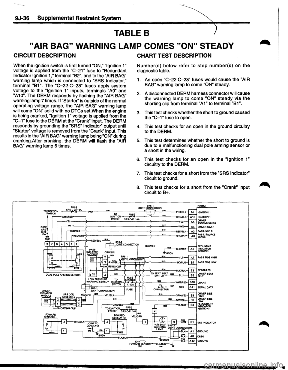
9J-36 Supplemental Restraint System
TABLE B
"AIR BAG" WARNING LAMP COMES "ON" STEADY
CIRCUIT DESCRIPTION
When the ignition switch is first turned "ON," "Ignition 1"
voltage is applied from the "C-21" fuse to "Redundant
Indicator Ignition 1 ,"terminal "B2", and to the "AIR BAG"
warning lamp which is connected to "SRS Indicator,"
terminal "B1". The "C-22·C-23" fuses apply system
voltage to the
"Ignition 1" inputs, terminals "A9" and
"A10". The DERM responds by flashing the "AIR BAG"
warning lamp 7 times. If "Starter" is outside of the normal
operating voltage range, the
"AIR BAG" warning lamp
will
come "ON" solid with no DTCs set. When the engine
is being cranked,
"Ignition 1" voltage is applied from the
"C-1" fuse to the DERM at the "Crank" input. The DERM
responds by grounding the
"SRS" Indicator" output until
"Starter" voltage is removed from the "Crank'' input. This
results in the
"AIR BAG" warning lamp being "ON" during
cranking.After cranking, the DERM
will flash the "AIR
BAG" warning lamp 6 times.
CHART TEST DESCRIPTION
Number(s) below refer to step number(s) on the
diagnostic table.
1. An open "C-22-C-23" fuses would cause the "AIR
BAG" warning lamp to come "ON" steady.
2. A disconnected DERM harness connector will cause
the warning
lamp to come "ON" steady via the
shorting clip from terminal "A1" to terminal "81".
3. This test checks whether the short to ground caused
the
"C-1" fuse to open.
4. This test checks for an open in the ground circuitry
to the DERM.
5. This test determines whether the short to ground is
due to a malfunctioning dual pole arming sensor or
a short
in the wiring.
6. This test checks for an open in the "Ignition 1"
circuitry to the DERM.
7. This test checks for a short from the "SRS Indicator''
circuit to ground.
8. This test checks for a short from the "Crank" input
circuit to 8+.
SRS-1 JOINT CONNECTION TO IGNITION FUSE SRS C·23 10A 1!015 '12 10 IGNITION I IGNITION 1 SWITCH
FUSE~ SRS C-24 10A .... R D
PASS.3eVLR PASS. SOURCE SENSE
PASS SlOE HIGH
PASS SlOE LOW
SERIAL DATA
SRS INDICATOR
..