fuse chart ISUZU TROOPER 1995 Owner's Guide
[x] Cancel search | Manufacturer: ISUZU, Model Year: 1995, Model line: TROOPER, Model: ISUZU TROOPER 1995Pages: 1928
Page 942 of 1928
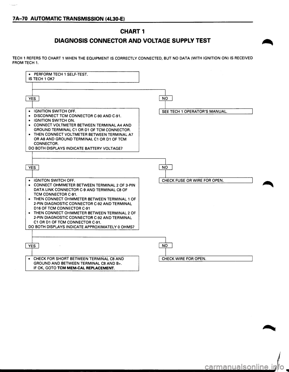
7A-70 AUTOMATIC TRANSMISSION (4L30-E)
CHART 1
DIAGNOSIS CONNECTOR AND VOLTAGE SUPPLY TEST
TECH 1 REFERS TO CHART 1 WHEN THE EQUIPMENT IS CORRECTLY CONNECTED, BUT NO DATA (WITH IGNITION ON) IS RECEIVED
FROM TECH 1.
• PERFORM TECH 1 SELF-TEST . IS TECH 1 OK?
~ ~
• IGNITION SWITCH OFF . I SEE TECH 1 OPERATOR'S MANUAL. I • DISCONNECT TCM CONNECTOR C-90 AND C-91 .
• IGNITION SWITCH ON .
• CONNECT VOLTMETER BETWEEN TERMINAL A4 AND GROUND TERMINAL C1 OR D1 OF TCM CONNECTOR.
•
THEN CONNECT VOLTMETER BETWEEN TERMINAL A7 OR AS AND GROUND TERMINAL C1 OR D1 OF TCM
CONNECTOR.
DO BOTH DISPLAYS INDICATE
BATTERY VOLTAGE?
+ ~ • IGNITON SWITCH OFF. I CHECK FUSE OR WIRE FOR OPEN. I • CONNECT OHMMETER BETWEEN TERMINAL 2 OF 3-PIN DATA LINK CONNECTOR C-9 AND TERMINAL CS OF
TCM CONNECTOR C-91.
•
THEN CONNECT OHMMETER BETWEEN TERMINAL 1 OF
2-PIN DIAGNOSTIC CONNECTOR C-92 AND TERMINAL D16 OF TCM CONNECTOR C-91
• THEN CONNECT OHMMETER BETWEEN TERMINAL 2 OF 2-PIN DIAGNOSTIC CONNECTOR C-92 AND TERMINAL C1 OR D1 OF TCM CONNECTOR C-91.
DO BOTH DISPLAYS INDICATE APPROXIMATELY 0 OHMS?
~ ~ • CHECK FOR SHORT BETWEEN TERMINAL CS AND I CHECK WIRE FOR OPEN. I GROUND AND BETWEEN TERMINAL CS AND B+. IF OK, GOTO TCM MEM-CAL REPLACEMENT.
____________ _,,(
Page 1252 of 1928
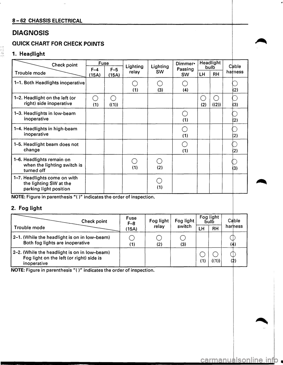
8-62 CHASSIS ELECTRICAL
DIAGNOSIS
QUICK CHART FOR CHECK POINTS ~ )-; '. ·'·• 1. Heaplight 1:·
~
Fuse Lighting Lighting Dimmer• Headlight c ~ble Passing bulb F-4
F-5 relay sw ha ness
T
(15A) (15A) sw LH RH
1-1. Both Headlights inoperative 0 0 0 b (1) (3) (4) 2)
1-2. Headlight on
the left (or 0 0 0
0 b right) side inoperative (1) ((1)) (2) ((2)) 3)
1-3. Headlights in low-beam 0 b inoperative (1) 2)
1-4. Headlights in high-beam 0 b inoperative
(1) 2)
1-5. Headlight beam does not 0 p
change (1) 2)
1-6. Headlights remain on 0 0 b when the lighting switch is
( 1) (2) 3) turned off
1-7. Headlights come on with 0 ~ the lighting SW at the
parking light position (1)
NOTE: Figure in parenthesis"( )" indicates the order of inspection.
2. Fog light
~
Fuse
Fog light Fog light Fog light Cc ble F-8 bulb
(15A) relay switch LH RH har ness Tr
2-1. (While the headlight is on in low-beam) 0 0 0 c ~ Both
fog lights are inoperative (1) (2) (3) ( )
2-2. (While the headlight is
on in low-beam) 0 0 CD Fog light on the left (or right) side is
( 1) ( ( 1)) ( ) inoperative
NOTE: Figure
in parenthesis"()" indicates the order of inspection.
~ -'
..
Page 1272 of 1928
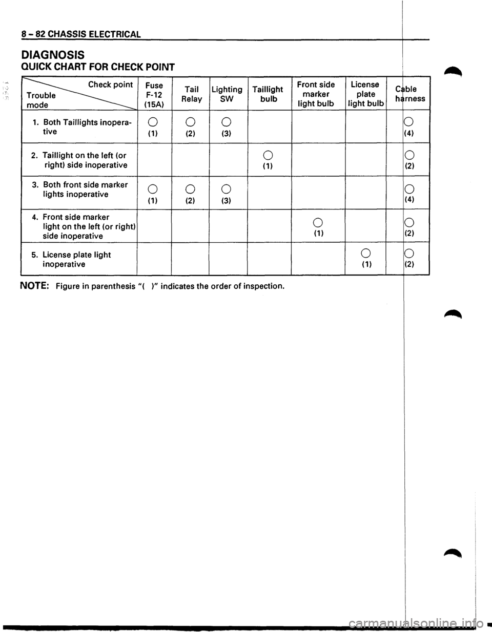
8 -82 CHASSIS ELECTRICAL
DIAGNOSIS
QUICK CHART FOR CHECK POINT
·~··
~
Fuse Front
side License ; Tail Lighting
Taillight
marker plate c ble '. F-12 e
Relay sw bulb he rness
e (15A) light bulb light bulb
1. Both Taillights inopera-0
0
0 0 tive (1) (2) (3) (4)
2. Taillight
on the left (or 0 0 right)
side inoperative
(1) (2)
3. Both front side marker 0 0
0 0 lights inoperative (1) (2) (3) (4)
4. Front
side marker 0 0 light on
the left (or right)
side inoperative (1) (2)
5. License plate light 0
0
inoperative (1) (2)
NOTE: Figure
in parenthesis "( )" indicates the order of inspection.
~
~
•
Page 1286 of 1928
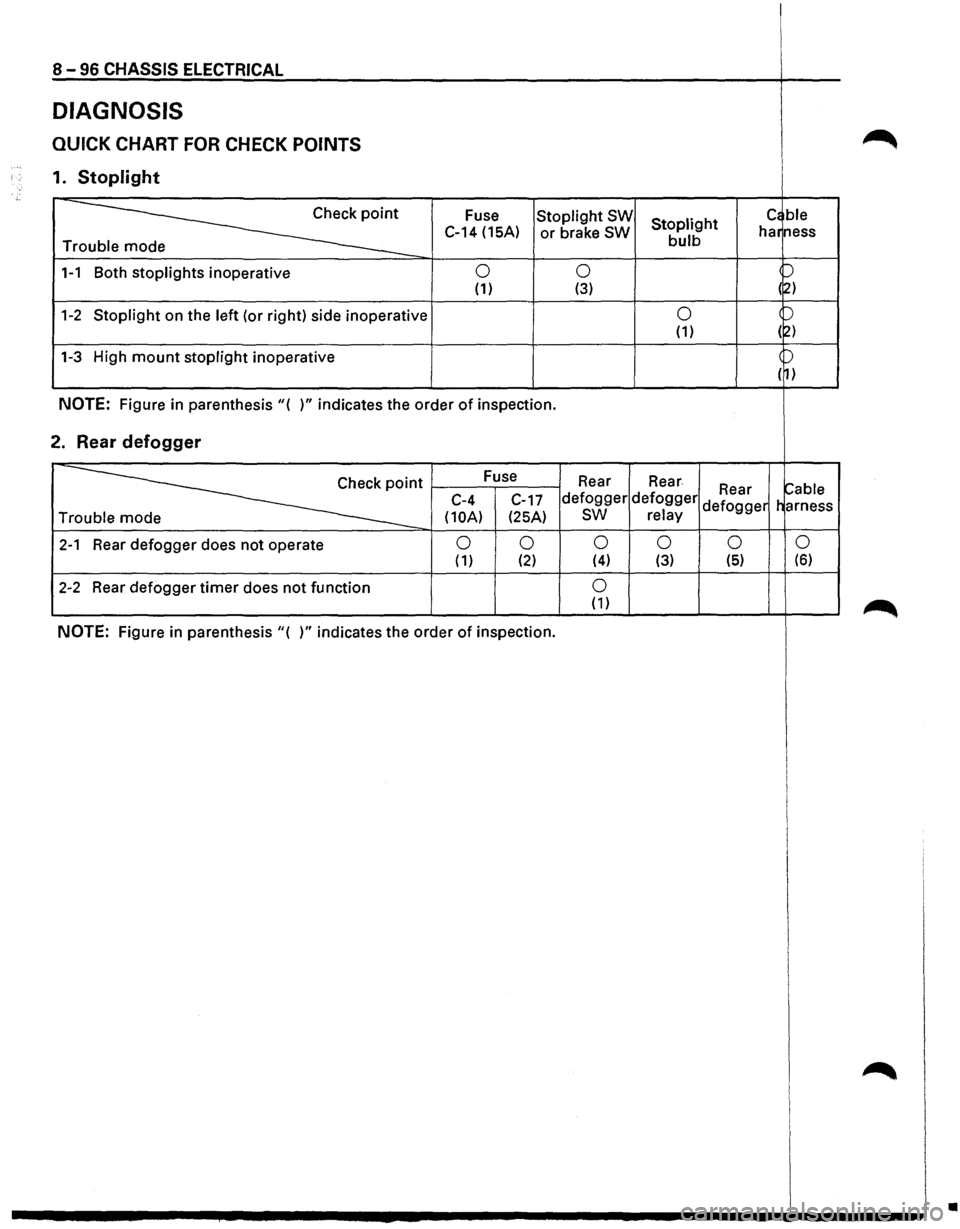
8-96 CHASSIS ELECTRICAL
DIAGNOSIS
QUICK CHART FOR CHECK POINTS
1. Stoplight
~
Fuse Stoplight SW Stoplight c~ ble
C-14 (15A) or brake SW bulb har
ness
Tr
1-1 Both stoplights inoperative 0 0 p
(1) (3) (~)
1-2 Stoplight on the left (or right) side inoperative 0 )
(1) (2)
1-3 High mount stoplight inoperative )
( 1)
NOTE: Figure in parenthesis"( )" indicates the order of inspection.
2. Rear defogger
~·
Fuse
Rear Rear ~able C-4
C-17 defogger defogger Rear
Tr
(10A) (25A) sw relay defogger
harness
2-1 Rear defogger does not operate 0 0 0 0 0
0 ( 1) (2) (4) (3) (5) (6)
2-2 Rear
defogger timer does not function 0 (1)
NOTE: Figure in parenthesis"( )" indicates the order of inspection.
•
Page 1301 of 1928
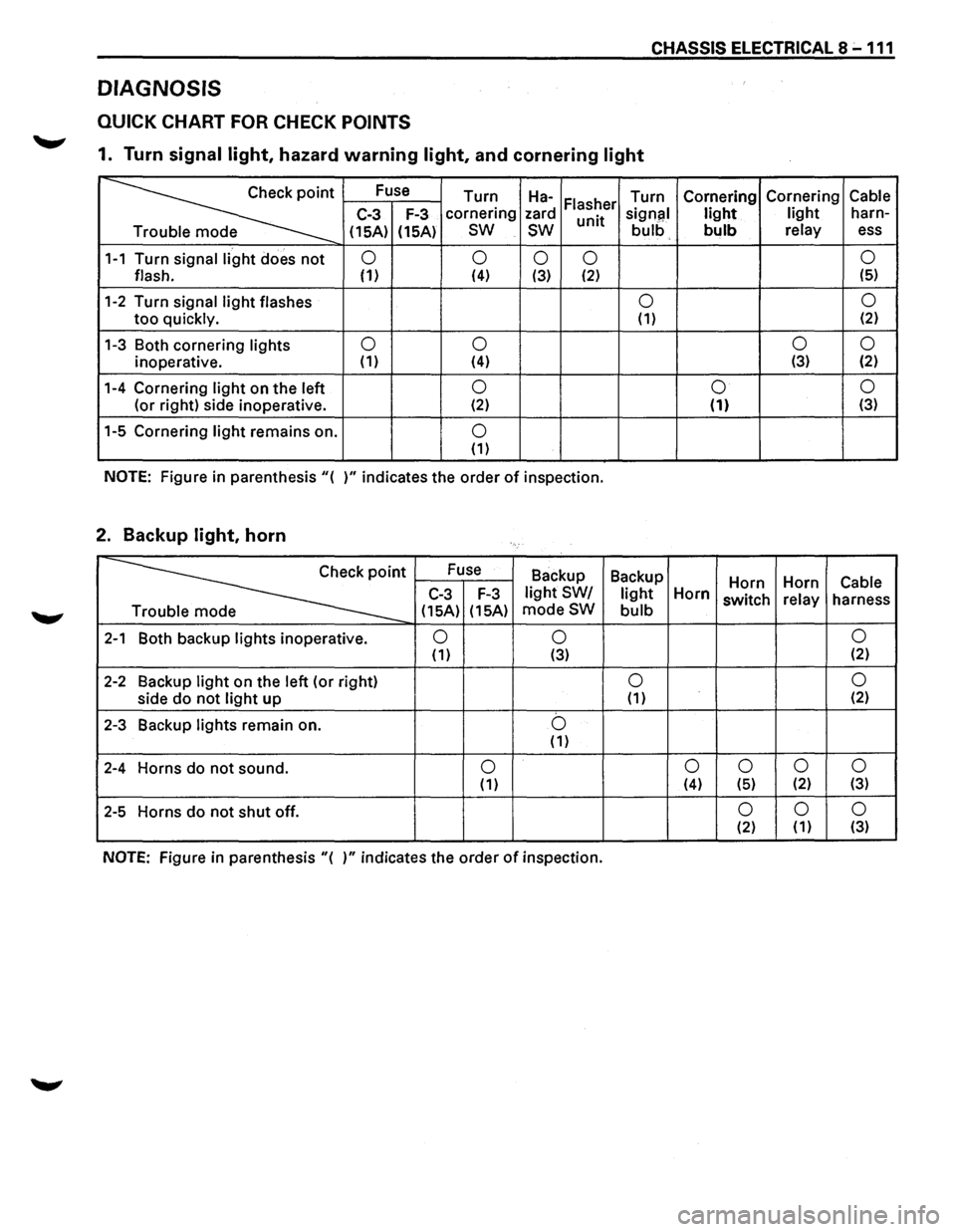
CHASSIS ELECTRICAL 8 -111
DIAGNOSIS
QUICK CHART FOR CHECK POINTS
1. Turn signal light, hazard warning light, and cornering light
~·
Fuse
Turn Ha-Turn Cornering Cornering Cable Flasher C-3 F-3 cornering
zard
unit signal light light harn-
e (15A)
(15A)
sw
sw bulb bulb relay ess
1-1 Turn signal light does not 0
0 0 0 0
flash. (1) (4) (3) (2) (5)
1-2 Turn
signal light flashes 0 0
too quickly. (1) (2)
1-3 Both
cornering lights 0
0 0
0
inoperative. (1)
(4) (3) (2)
1-4 Cornering light on the left 0 0 0
(or
right) side inoperative. (2) (1) (3)
1-5 Cornering light remains on. 0 (1)
NOTE: Figure in parenthesis"{ )"indicates the order of inspection.
2. Backup light, horn
~·
Fuse
Backup Backup
Horn Horn Cable C-3 F-3 light SW/ light Horn switch relay
harness
e {15A) {15A) modeSW bulb
2-1 Both
backup lights inoperative. 0 0 0 (1) {3) {2)
2-2 Backup light on
the left (or right) 0 0
side do not light up {1) (2)
2-3 Backup lights remain on. b {1)
2-4 Horns do not sound. 0 0
0
0 0 {1) (4) {5) {2) (3)
2-5 Horns do not shut off. 0 0 0 {2) (1) (3)
NOTE: Figure
in parenthesis "{ )" indicates the order of inspection.
Page 1304 of 1928
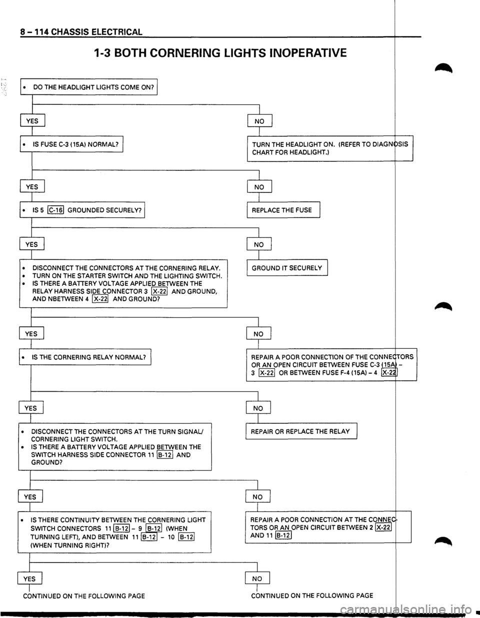
8 -114 CHASSIS ELECTRICAL
1-3 BOTH CORNERING LIGHTS INOPERATIVE
~ : ...
DO THE HEADLIGHT LIGHTS COME ON? I •
I
YES
I NO I
1
• IS FUSE C-3 {15A) NORMAL? I TURN THE HEADLIGHT ON. {REFER TO DIAGN
PSIS
CHART
FOR HEADLIGHT.)
I
YES
I NO I
I
• IS 5 IC-161 GROUNDED SECURELY? REPLACE THE FUSE I
I
YES
I NO I
I
• DISCONNECT THE CONNECTORS AT THE CORNERING RELAY . GROUND IT SECURELy I
• TURN ON THE STARTER SWITCH AND THE LIGHTING SWITCH .
• IS THERE A BATTERY VOLTAGE APPLIED BETWEEN THE
RELAY
HARNESS SIDE CONNECTOR 3 IX-221 AND GROUND, AND NBETWEEN 4 IX-221 AND GROUND?
~
I
YES
I NO I
I
• IS THE CORNERING RELAY NORMAL? I REPAIR A POOR CONNECTION OF THE CONNEC TORS
OR AN OPEN CIRCUIT BETWEEN FUSE C-3 ~ 3 IX-221 OR BETWEEN FUSE F-4 {15A)-4 X-2~
I
YES
I NO I
I
• DISCONNECT THE CONNECTORS AT THE TURN SIGNAL/ REPAIR OR REPLACE THE RELAY I CORNERING LIGHT SWITCH.
• IS THERE A BATTERY VOLTAGE APPLIED BETWEEN THE
SWITCH HARNESS SIDE CONNECTOR 11IB-12I AND GROUND?
I
YES
I NO I
I
• IS THERE CONTINUITY BETWEEN THE CORNERING LIGHT REPAIR A
POOR CONNECTION AT THE CONNI;,C
SWITCH CONNECTORS
11IB·121-i IB-yl {WHEN TORS OR AN OPEN CIRCUIT BETWEEN 2IX-22I
TURNING LEFT), AND BETWEEN 11 B-12 -10 IB-121 AND 11IB-12I
~ {WHEN TURNING RIGHT)?
I
YES
NO I
cbNTINUED ON THE FOLLOWING PAGE I CONTINUED ON THE FOLLOWING PAGE
..
Page 1336 of 1928
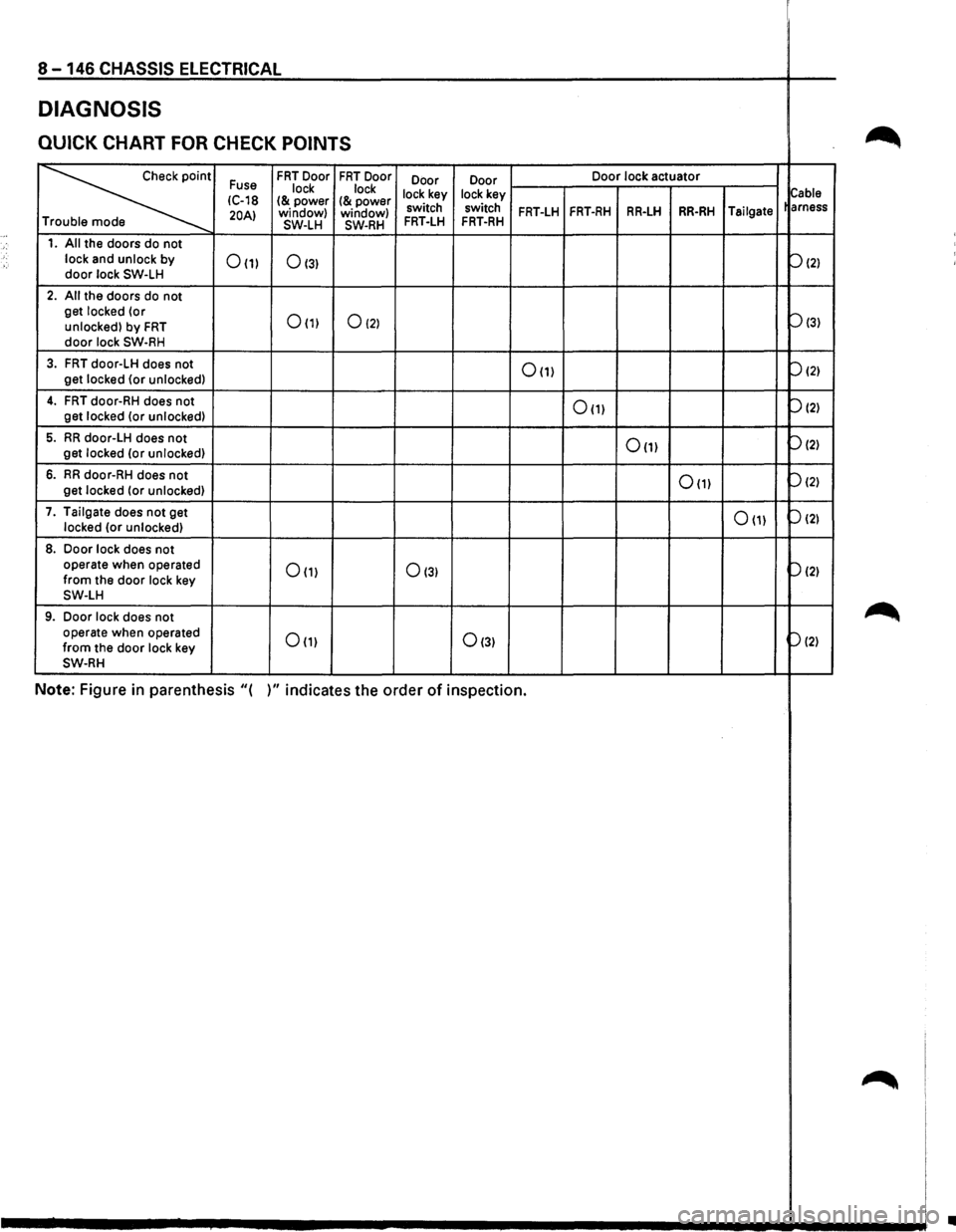
8 -146 CHASSIS ELECTRICAL
DIAGNOSIS
QUICK CHART FOR CHECK POINTS ~
~
Fuse FRT Door FRT Door
Door Door Door
lock actuator
lock lock
lock key lock key
Cable IC-18 I& power I& power 20AI window)
window) switch switch FRT-LH FRT-RH RR-LH RR-RH Tailgate
arness
T SW-LH SW-RH FRT-LH FRT-RH
1. All the doors do not
lock and unlock by
door lock SW-LH 0(1) 0131
P121
2. All the doors do not
get locked (or
0(1) 0121 Pl31 unlocked) by FRT door lock SW-RH
3. FRT door-LH does not 0(1) P121 get locked {or unlocked)
4. FRT door-RH does not 0111 P121 get
locked (or unlocked)
5. RR door-LH does not 0(1) P121 get locked (or unlocked)
6. RR door-RH does not 0111 P121 get
locked (or unlocked)
7. Tailgate does
not get 0111 P121 locked (or unlocked)
8. Door lock does not
operate when operated 0111 0131 p(2) from the door lock key SW-LH
9. Door lock does not ~ operate when operated Om 0131 P121 from the door lock key SW-RH
Note: Figure in parenthesis "( )" indicates the order of inspection.
~
•
Page 1350 of 1928
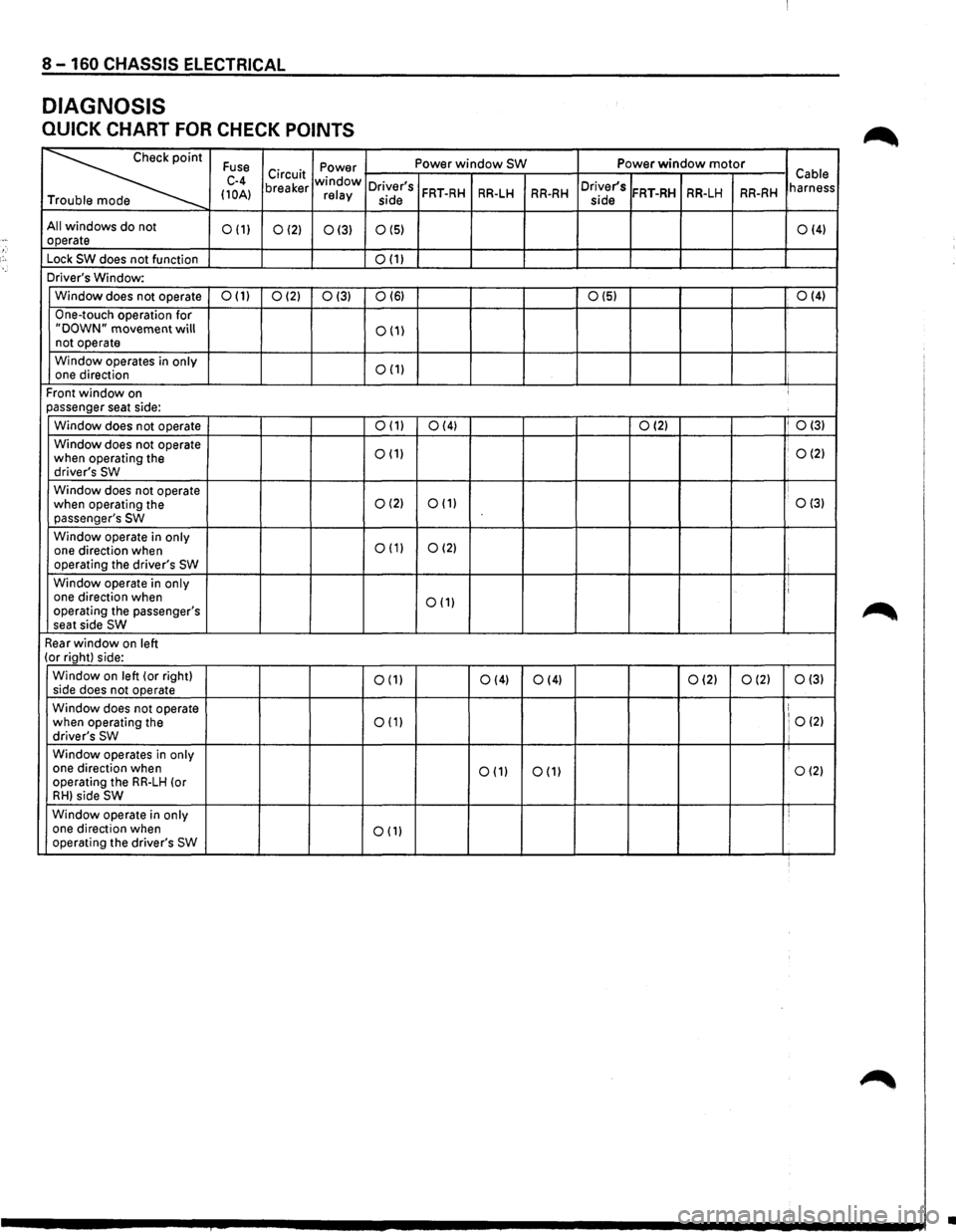
8-160 CHASSIS ELECTRICAL
DIAGNOSIS
QUICK CHART FOR CHECK POINTS
~
Fuse Power Power window SW Power window motor
C-4 Circuit window Cable
(10A) breaker relay Driver's FRT-RH RR-LH RR-RH Driver's FRT-RH RR-LH RR-RH harness
T side
side
All windows do not 0(1) 0(2) 0(3) 0(5) 0(4) operate
Lock
SW does not function 0(1)
Driver's Window:
Window does not operate
0(1) 0(2) 0(3) 0(6) 0(5) 0(4)
One-touch
operation for "DOWN" movement will 0(1) not operate
Window operates in
only 0(1) one direction
Front
window on ' passenger seat side:
Window does not operate
0(1) 0(4) 0(2) I 0(3)
Window
does not operate 0(1) . 0(2) when operating the
driver's SW
Window does not operate
when operating the 0(2) 0(1) 0(3) passenger's SW
Window operate in only 0(1) 0(2) one direction when
operating the driver's SW
Window operate in only I one direction when 0(1) operating the passenger's
seat side SW
Rear window on left (or right) side:
Window
on left (or right) 0(1) 0(4) side
does not operate 0(4) 0(2) 0(2) 0(3)
Window does not operate ! 0(2) when operating the 0(1) driver's SW ' Window operates in only one direction when
operating the RR-LH (or 0(1) 0(1) 0(2)
RH) side SW
Window
operate in only i one direction when 0(1) operating the driver's SW
•
Page 1400 of 1928
-j.:,
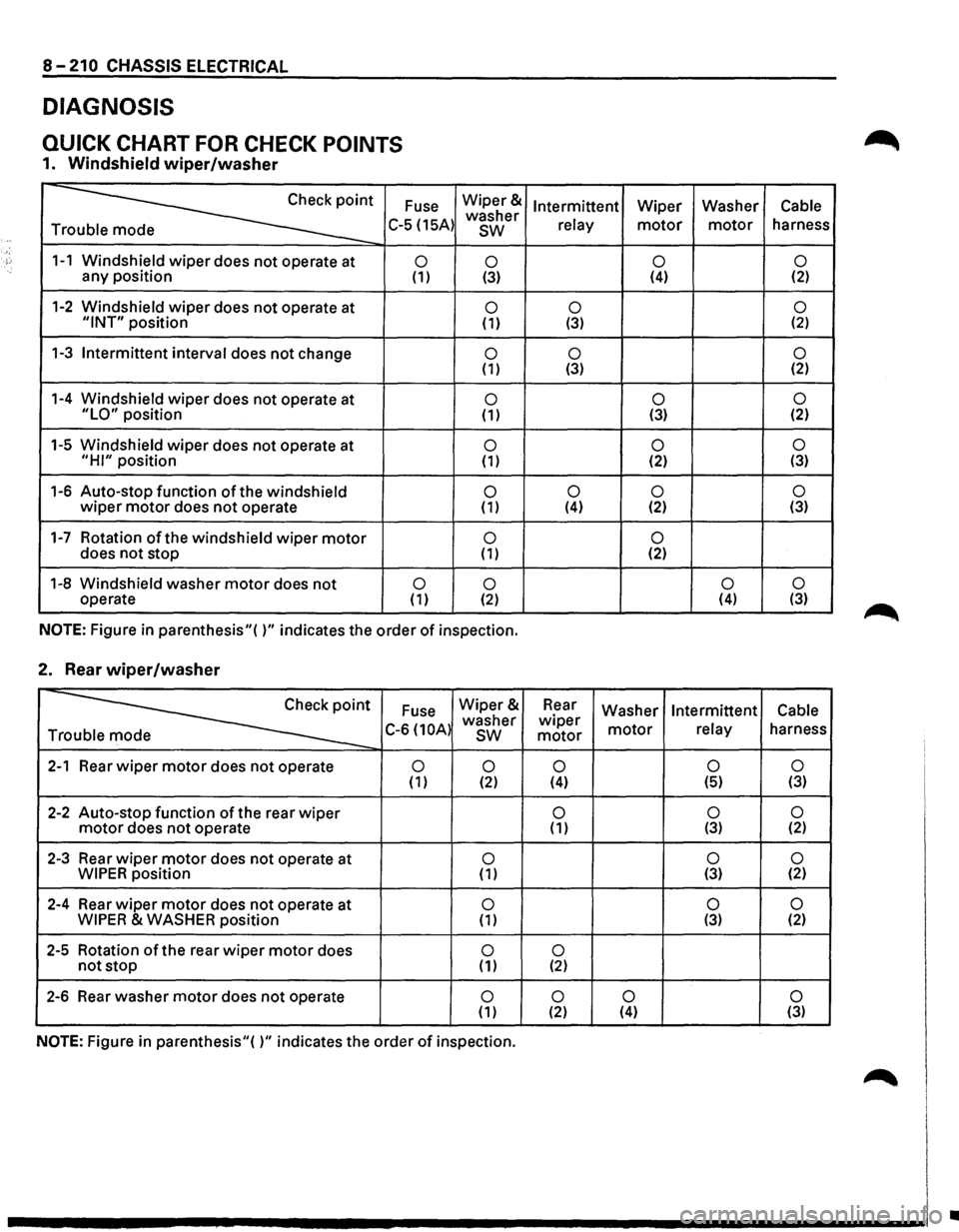
8-210 CHASSIS ELECTRICAL
DIAGNOSIS
QUICK CHART FOR CHECK POINTS
1. Windshield wiper/washer
Fuse
~· T C-5 (15A)
1-1 Windshield wiper does not operate at 0 any position (1)
1-2 Windshield wiper does not operate at "INT" position
1-3
Intermittent interval does not change
1-4 Windshield
wiper does not operate at "LO" position
1-5 Windshield
wiper does not operate at
"HI" position
1-6 Auto-stop function
of the windshield wiper motor does not operate
1-7 Rotation of the windshield wiper motor does not stop
1-8 Windshield washer
motor does not 0 operate (1)
Wiper&
washer
sw
0 (3)
0 (1)
0 (1)
0 (1)
0 (1)
0 (1)
0 ( 1)
0 (2)
NOTE:
Figure in parenthesis"( )" indicates the order of inspection.
2. Rear wiper/washer
~
Fuse Wiper&
C-6 (10A) washer T sw
2-1 Rear wiper motor does not operate 0
0 (1) (2)
2-2 Auto-stop function of the rear wiper motor does not operate
2-3 Rear
wiper motor does not operate at 0 WIPER position (1)
2-4 Rear
wiper motor does not operate at 0 WIPER & WASHER position (1)
2-5 Rotation of the rear wiper motor does 0 not stop ( 1)
2-6 Rear
washer motor does not operate 0 ( 1)
NOTE: Figure in parenthesis"( )" indicates the order of inspection.
Intermittent Wiper Washer Cable
relay
motor motor harness
0 0 (4) (2)
0
0 (3) (2)
0
0 (3) (2)
0 0 (3) (2)
0
0 (2) (3)
0
0 0 (4) (2) (3)
0 (2)
0 0 (4)
(3)
Rear
Washer Intermittent Cable wiper motor relay harness motor
0 0 0 (4) (5) (3)
0
0 0 ( 1) (3) (2)
0
0 (3) (2)
0 0 (3) (2)
0 (2)
0
0 0 (2) (4) (3)
•
Page 1426 of 1928
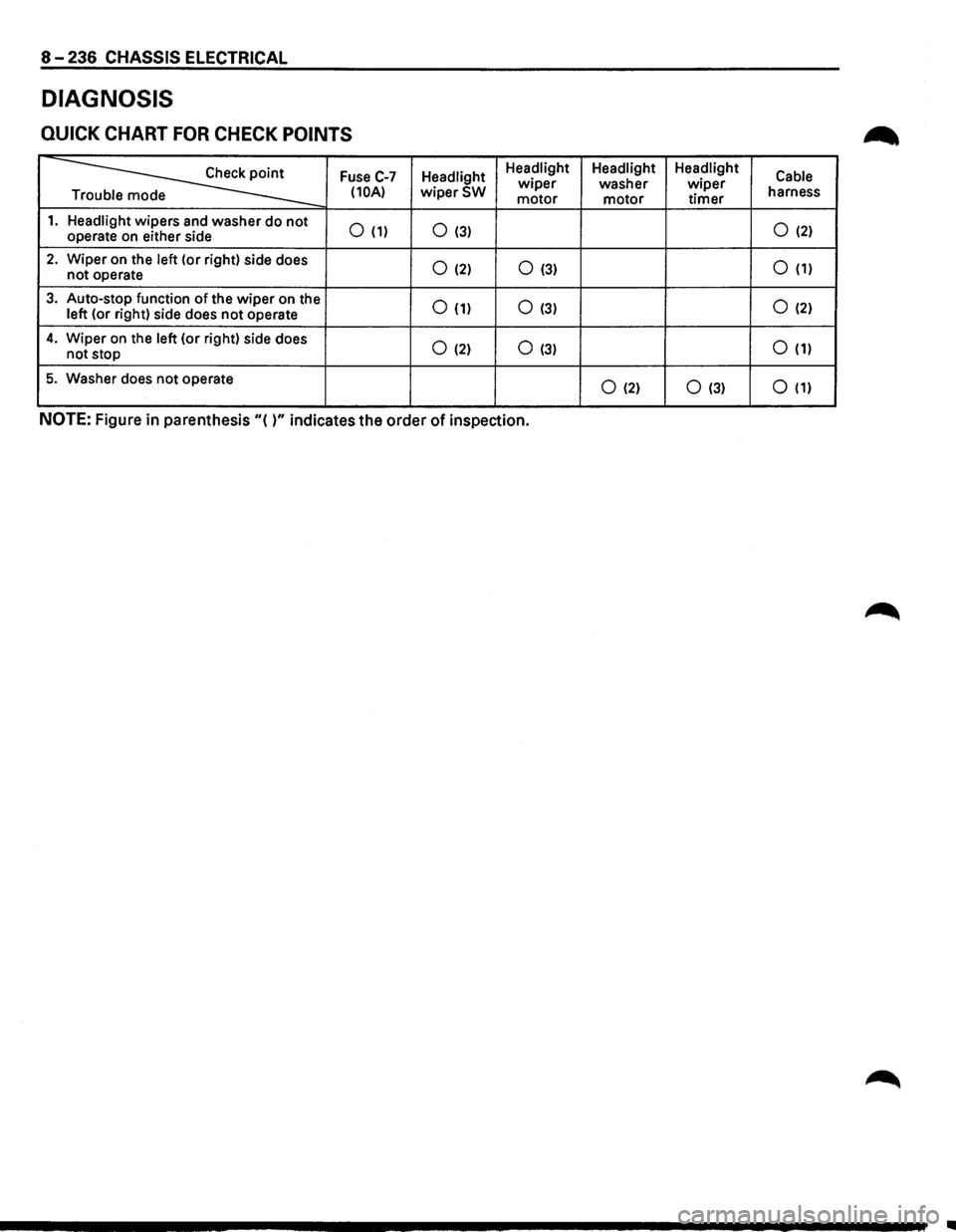
8-236 CHASSIS ELECTRICAL
DIAGNOSIS
QUICK CHART FOR CHECK POINTS
~
Fuse C-7 Headlight Headlight
Headlight Headlight
Cable wiper washer wiper (10A) wiperSW motor motor timer harness
e
1. Headlight wipers and washer do not 0 (1) 0 (3) 0 (2) operate on either side
2. Wiper on the left (or right) side does 0 (2) 0 (3) 0 (1) not operate
3. Auto-stop function of the wiper on the 0 (1) 0 (3) 0 (2) left (or right) side does not operate
4. Wiper on the left (or right) side does 0 (2) 0 (3) 0 (1) not stop
5. Washer does not operate 0 (2) 0 (3) 0 (1)
NOTE: Figure in parenthesis "( )" indicates the order of inspection.