fuse chart ISUZU TROOPER 1995 Repair Manual
[x] Cancel search | Manufacturer: ISUZU, Model Year: 1995, Model line: TROOPER, Model: ISUZU TROOPER 1995Pages: 1928
Page 1700 of 1928
9J-76 Supplemental Restraint System
DTC34
DUAL POLE ARMING SENSOR IGNITION FEED OPEN
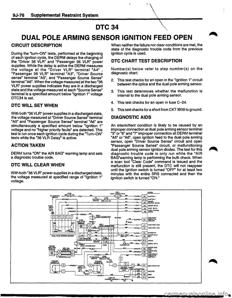
CIRCUIT DESCRIPTION
During the "turn-ON" tests, performed at the beginning
of each ignition cycle, the DERM delays the charging of
the
"Driver 36 VLR" and "Passenger 36 VLR" power
supplies.
While the delay is active the DERM measures
the voltage at the "Driver VLR" terminal "A4" ,
"Passenger 36 VLR" terminal "A3", "Driver Source
sense" terminal "AS", and "Passenger Source Sense"
terminal "A6". When the voltage measured at the two "36
VLR" power supplies indicates they are in a discharged
state and the voltage measured at each
"Source Sense"
terminal is a specified amount below "Ignition 1" voltage
DTC34 is set.
DTC WILL SET WHEN
With both "36 VLR" power supplies in a discharged state,
the voltage measured at "Driver
Source Sense" terminal
"AS" and "Passenger Source Sense" terminal "A6" are
simultaneously a specified amount below
"Ignition 1"
voltage and no "higher priority faults" are detected. This
test is run once each ignition cycle during the "Turn-ON"
tests while the "36
VLR Delay" is active.
ACTION TAKEN
DERM turns "ON" the AIR BAG" warning lamp and sets
a diagnostic trouble code.
DTC WILL CLEAR WHEN
With both "36 VLR" power supplies in a discharged state,
the voltage measured at specified range of
"Ignition 1"
voltage. When
neither the failure nor clear conditions are met, the
state of the diagnostic trouble code from the previous
ignition cycle is used.
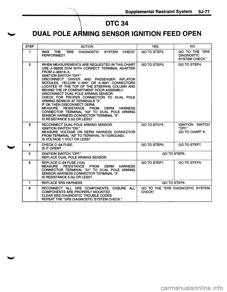
DTC CHART TEST DESCRIPTION
Number(s) below refer to step number(s) on the
diagnostic chart.
2. This test checks for an open in the "Ignition 1" circuit
between the
splice and the dual pole arming sensor.
3. This test determines whether the malfunction is
internal to the dual pole arming sensor.
4. This test checks for an open in fuse C-24.
s. This test checks for a short from CKT 1809 to ground.
DIAGNOSTIC AIDS
An intermittent condition is likely to be caused by an
improper connection at dual pole arming sensor terminal
"3" or "6" and "7" improper connection at DERM terminal
"AS" or "A6", open ignition feed to the dual pole arming
sensor, open "Driver
Source Sense" circuit and open
"Passenger
Source Sense" circuit, or malfunctioning
dual pole arming sensor ignition diodes. The test for this
diagnostic trouble code is only run while the "AIR
BAG"warning lamp is performing the bulb check. When
a scan tool "Clear Code" command is issued and the
malfunction
is still present, the DTC will not reappear
until the ignition switch is turned
"OFP' for at least two
minutes with the entire
SRS connected and then the
ignition switch is turned
"ON."
Ill
Page 1701 of 1928
Supplemental Restraint System 9J-77
DTC34
'-" DUAL POLE A MING SENSOR IGNITION FEED OPEN
STEP
ACTION YES NO
1 WAS THE "SRS
DIAGNOSTIC SYSTEM CHECK" GOTOSTEP2. GO TO THE "SRS
PERFORMED? DIAGNOSTIC
SYSTEM CHECK."
2 WHEN MEASUREMENTS ARE REQUESTED IN THIS CHART GOTOSTEP3. GOTO STEP4.
USE J-39200 DVM WITH CORRECT TERMINAL ADAPTER FROM J-35616-A. IGNITION SWITCH "OFF."
DISCONNECT DRIVER
AND PASSENGER INFLATOR
MODULES, YELLOW 2-WAY OR 4-WAY CONNECTORS
LOCATED AT THE TOP OF THE STEERING COLUMN AND BEHIND THE 1/P COMPARTMENT DOOR ASSEMBLY.
DISCONNECT DUAL POLE ARMING SENSOR.
CHECK FOR PROPER CONNECTION TO
DUAL POLE
ARMING SENSOR AT TERMINALS "3".
IF OK THEN DISCONNECT DERM.
MEASURE RESISTANCE FROM DERM HARNESS
CONNECTOR TERMINAL "A9" TO DUAL POLE ARMING
SENSOR HARNESS CONNECTOR TERMINAL "3". IS RESISTANCE 5.00 OR LESS?
3 RECONNECT DUAL POLE ARMING SENSOR. GO TO STEPS. IGNITION
SWITCH
IGNITION SWITCH "ON." "OFF."
MEASURE VOLTAGE ON DERM HARNESS
CONNECTOR GO
TO CHART A.
FROM TERMINAL "AS" TO TERMINAL "A 1 "(GROUND).
IS VOLTAGE 1 VOLT OR LESS?
4 CHECK C-24 FUSE. GOTO STEP6. GOTOSTEP7.
IS IT OPEN?
5 IGNITION SWITCH "OFF." GOTOSTEP8.
REPLACE DUAL POLE ARMING SENSOR.
6 REPLACE C-24 FUSE.(10A) GOTOSTEP7. GOTO STEPS.
MEASURE RESISTANCE FROM DERM HARNESS
CONNECTOR TERMINAL "A1" TO DUAL POLE ARMING
SENSOR HARNESS CONNECTOR TERMINAL "3".
IS RESISTANCE
5.00 OR LESS?
7 REPLACE SRS HARNESS GOTOSTEP8.
8 RECONNECT ALL SRS COMPONENTS, ENSURE ALL GO TO THE "SRS DIAGNOSTIC SYSTEM
COMPONENTS
ARE PROPERLY MOUNTED. CHECK".
CLEAR SRS DIAGNOSTIC TROUBLE CODES. REPEAT THE "SRS DIAGNOSTIC SYSTEM CHECK."
Page 1706 of 1928
9J·82 Supplemental Restraint System
DTC37
HYBRID INFLATOR LOW PRESSURE
CIRCUIT DESCRIPTION
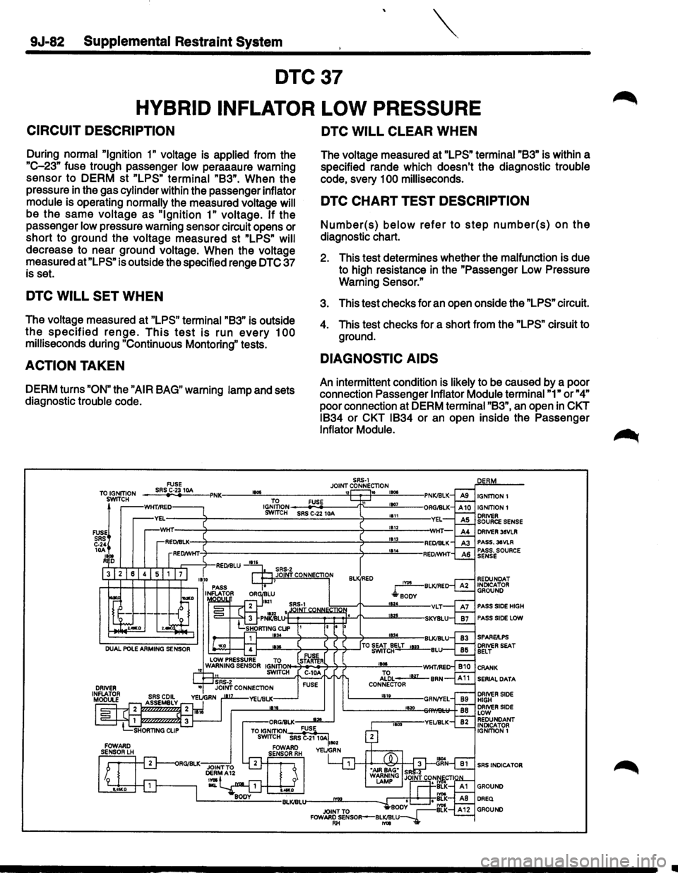
During normal "Ignition 1" voltage is applied from the
"C-23" fuse trough passenger low peraaaure warning
sensor to DERM st
"LPS" terminal "83". When the
pressure in the gas cylinder within the passenger inflator
module is operating normally the measured voltage will
be the same voltage as "Ignition 1" voltage. If the
passenger
low pressure warning sensor circuit opens or
short to ground the voltage measured st
"LPS" will
decrease to near ground voltage. When the voltage
measured
at"LPS" is outside the specified renge DTC 37
is set.
DTC WILL SET WHEN
The voltage measured at "LPS" terminal "83" is outside
the specified renge. This test is run every 100
milliseconds during "Continuous Montoring" tests.
ACTION TAKEN
DERM turns "ON" the "AIR BAG" warning lamp and sets
diagnostic trouble code.
DTC WILL CLEAR WHEN
The voltage measured at "LPS" terminal "83" is within a
specified rande which doesn't the diagnostic trouble
code, svery
100 milliseconds.
DTC CHART TEST DESCRIPTION
Number(s) below refer to step number(s) on the
diagnostic chart.
2. This test determines whether the malfunction is due
to high resistance
in the "Passenger Low Pressure
Warning
Sensor."
3. This test checks for an open onside the "LPS" circuit.
4. This test checks for a short from the "LPS" cirsuit to
ground.
DIAGNOSTIC AIDS
An intermittent condition is likely to be caused by a poor
connection Passenger
Inflator Module terminal "1" or "4"
poor connection at DERM terminal "83", an open in CKT
1834 or CKT 1834 or an open inside the Passenger
Inflator Module.
SRS-1 JOINT CONNECTION 10 , ... IGNITION!
IGNITION 1 ORIVER SOURCE SENSE DRIVER 38VLR PASS.3eVLR PASS. SOURCE SENSE
REDUNDAT INDICATOR GROUND
PASS SIDE HIGH
PASS SIDE LOW
SPARE/I.PS DRIVER SEAT BELT
SERIAL DATA
DRIVER SIDE HIGH DRIVER SIDE LOW REDUNDANT INDICATOR IGNITION!
SRS INDICATOR
..
Page 1710 of 1928
9J-86 Supplemental Restraint System
DTC43
DRIVER SOURCE FEED LOW
CIRCUIT DESCRIPTION
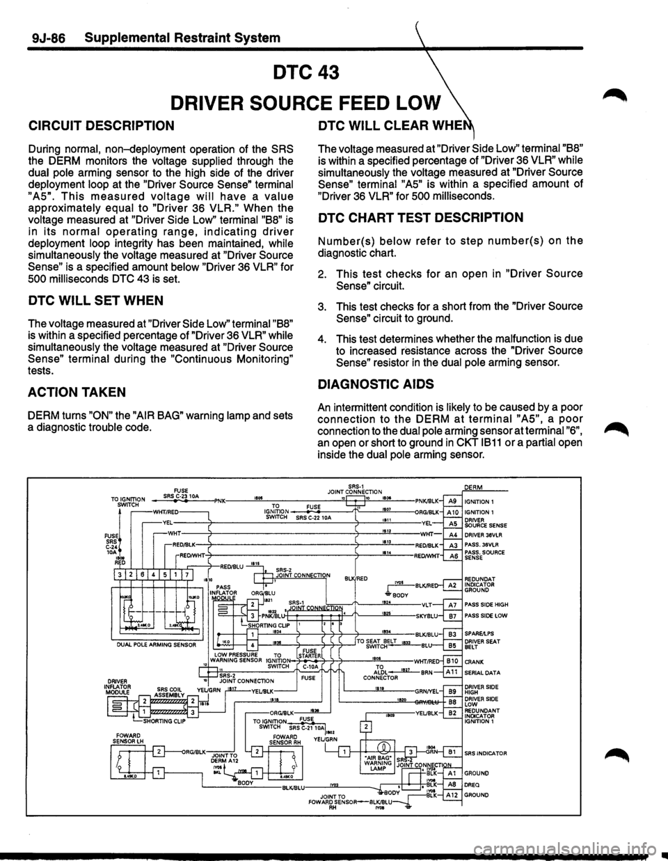
During normal, non-deployment operation of the SRS
the DERM monitors the voltage supplied through the
dual pole arming sensor to the high side of the driver
deployment loop at the "Driver Source Sense" terminal
"AS".
This measured voltage will have a value
approximately equal to "Driver 36 VLR." When the
voltage measured at "Driver Side Low" terminal "88" is
in its normal operating range, indicating driver
deployment loop integrity has been maintained, while
simultaneously
the voltage measured at "Driver Source
Sense"
is a specified amount below "Driver 36 VLR" for
SOO milliseconds DTC 43 is set.
DTC WILL SET WHEN
The voltage measured at "Driver Side Low" terminal "88"
is within a specified percentage of "Driver 36 VLR" while
simultaneously
the voltage measured at "Driver Source
Sense" terminal
during the "Continuous Monitoring"
tests.
ACTION TAKEN
DERM turns "ON" the "AIR BAG" warning lamp and sets
a diagnostic
trouble code.
DTC WILL CLEAR WHE
The voltage measured at "Driver Side Low" terminal "88"
is within a specified percentage of "Driver 36 VLR" while
simultaneously
the voltage measured at "Driver Source
Sense" terminal "AS"
is within a specified amount of
"Driver 36 VLR" for SOO milliseconds.
DTC CHART TEST DESCRIPTION
Number(s) below refer to step number(s) on the
diagnostic chart.
2. This test checks for an open in "Driver Source
Sense"
circuit.
3. This test checks for a short from the "Driver Source
Sense"
circuit to ground.
4. This test determines whether the malfunction is due
to increased resistance across the "Driver
Source
Sense"
resistor in the dual pole arming sensor.
DIAGNOSTIC AIDS
An intermittent condition is likely to be caused by a poor
connection to the DERM at terminal "AS", a poor
connection to the dual pole arming sensor at terminal "6",
an open or short to ground in CKT 1811 or a partial open
inside the
dual pole arming sensor.
SRS-1 FUSE JOINT CONNECTION ___ sR~S~C-~23-10_A __ ~'NK----~·~·~~----------~~-Pw--~•·~~---TO IGNITION SWITCH
FUSE! SRS C-24 10A , ... REO
TO FUSE 1001 ~~~~g~ _S_R_.S C,.:;.:·2:i-2 -10A--~r'f"---....l!!!<'----• 1111
181Z 1113
1814
B RED
IGNITION 1 IGNITION 1
DRIVER 36VLR PASS.38VLR PASS. SOURCE SENSE
REDUNOAT INDICATOR GROUND
PASS SlOE HIGH
PASS SIDE LOW
SERIAL DATA
SRS INDICATOR
..
Page 1712 of 1928
9J-88 Supplemental Restraint System
DTC44
PASSENGER SOURCE FEED LOW
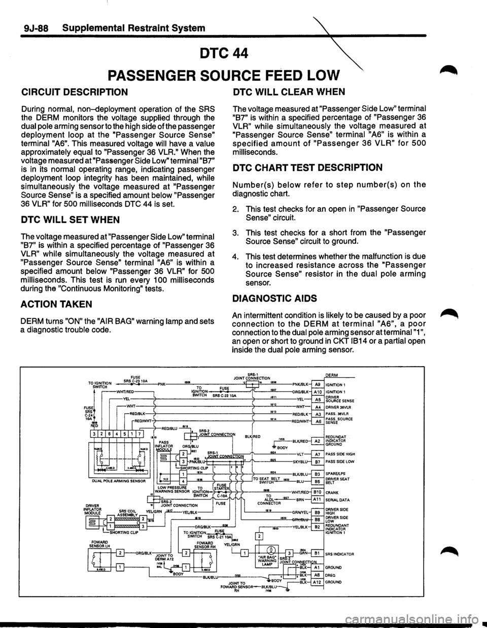
CIRCUIT DESCRIPTION
During normal, non-deployment operation of the SRS
the DERM monitors the voltage supplied through the
dual pole arming sensor to the high side ofthe passenger
deployment
loop at the "Passenger Source Sense"
terminal
"AS". This measured voltage will have a value
approximately equal to "Passenger 3S VLR." When the
voltage measured at "Passenger Side Low" terminal "87"
is in its normal operating range, indicating passenger
deployment
loop integrity has been maintained, while
simultaneously
the voltage measured at "Passenger
Source Sense" is a specified amount below "Passenger
3S VLR" for 500 milliseconds DTC 44 is set.
DTC WILL SET WHEN
The voltage measured at "Passenger Side Low" terminal
"87"
is within a specified percentage of "Passenger 3S
VLR" while simultaneously the voltage measured at
"Passenger Source Sense" terminal "AS" is within a
specified amount
below "Passenger 3S VLR" for 500
milliseconds.
This test is run every 1 00 milliseconds
during the "Continuous Monitoring" tests.
ACTION TAKEN
DERM turns "ON" the "AIR BAG" warning lamp and sets
a diagnostic
trouble code.
TO IGNITION SWITCH
FUSEj SRS C·24
10A , ... D
FUSE SRS C·23 10A 1001
DTC WILL CLEAR WHEN
The voltage measured at "Passenger Side Low" terminal
"87"
is within a specified percentage of "Passenger 3S
VLR" while simultaneously the voltage measured at
"Passenger Source Sense" terminal "AS" is within a
specified amount of "Passenger 3S VLR" for 500
milliseconds.
DTC CHART TEST DESCRIPTION
Number(s) below refer to step number(s) on the
diagnostic chart.
2. This test checks for an open in "Passenger Source
Sense" circuit.
3. This test checks for a short from the "Passenger
Source Sense" circuit to ground.
4. This test determines whether the malfunction is due
to increased resistance across the
"Passenger
Source Sense" resistor in the dual pole arming
sensor.
DIAGNOSTIC AIDS
An intermittent condition is likely to be caused by a poor
connection to the DERM at terminal "AS", a poor
connection to the dual pole arming sensor at terminal "1",
an open or short to ground in CKT 1814 or a partial open
inside the
dual pole arming sensor.
SRS-1 JOINT CONNECTION ~ IGNITION1
DRIVER 36VLR PASS. l&VLR PASS. SOURCE SENSE
PASS SIDE HIGH PASS SIDE LOW
1---""--:t--':1--7-7---7---""103"-4 --BLKIBLU 1--""--7-------:7-7--7--'TO ~fc~E-LT_,.,_BLU
~~~~~7----~11~~---W~fflE .J~L -----llli-BRN CONNECTOR 1811 11!120
..
Page 1714 of 1928
9J-90 Supplemental Restraint System
DTC51
FRONTAL
CRASH DETECTED
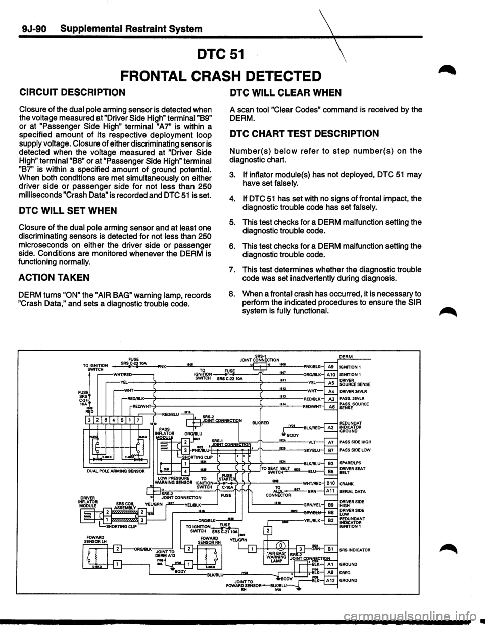
CIRCUIT DESCRIPTION
Closure of the dual pole arming sensor is detected when
the voltage measured at "Driver
Side High" terminal "89"
or at "Passenger Side High" terminal "A7" is within a
specified
amount of its respective deployment loop
supply voltage.
Closure of either discriminating sensor is
detected when the voltage measured at "Driver
Side
High" terminal "88" or at "Passenger Side High" terminal
"87" is within a specified amount of ground potential.
When both conditions are met simultaneously
on either
driver side
or passenger side for not less than 250
milliseconds "Crash Data" is recorded and DTC 51 is set.
DTC WILL SET WHEN
Closure of the dual pole arming sensor and at least one
discriminating sensors is detected for not less than
250
microseconds on either the driver side or passenger
side. Conditions are monitored whenever the DERM is
functioning
normally.
ACTION TAKEN
DERM turns "ON" the "AIR BAG" warning lamp, records
"Crash
Data," and sets a diagnostic trouble code.
TO IGNITION SWITCH
FUSE! SRS C-24 10A 1101 R D
DTC WILL CLEAR WHEN
A scan tool "Clear Codes" command is received by the
DERM.
DTC CHART TEST DESCRIPTION
Number(s) below refer to step number(s) on the
diagnostic chart.
3. If inflator module(s) has not deployed, DTC 51 may
have set falsely.
4. If DTC 51 has set with no signs of frontal impact, the
diagnostic trouble code has set falsely.
5. This test checks for a DERM malfunction setting the
diagnostic trouble code.
6. This test checks for a DERM malfunction setting the
diagnostic trouble code.
7. This test determines whether the diagnostic trouble
code was set inadvertently during diagnosis.
8. When a frontal crash has occurred, it is necessary to
perform the indicated procedures to ensure the
SIR
system is fully functional.
IGNITION 1
DRIVER 36VLR PASS.3SVLR PASS. SOURCE SENSE
PASS SIDE HIGH
PASS SIDE LCIW
SERIAL DATA
SAS INDICATOR
Page 1720 of 1928
9J-96 Supplemental Restraint System
DTC54
PASSENGER SIDE LOW HIGH RESISTA E
CIRCUIT DESCRIPTION
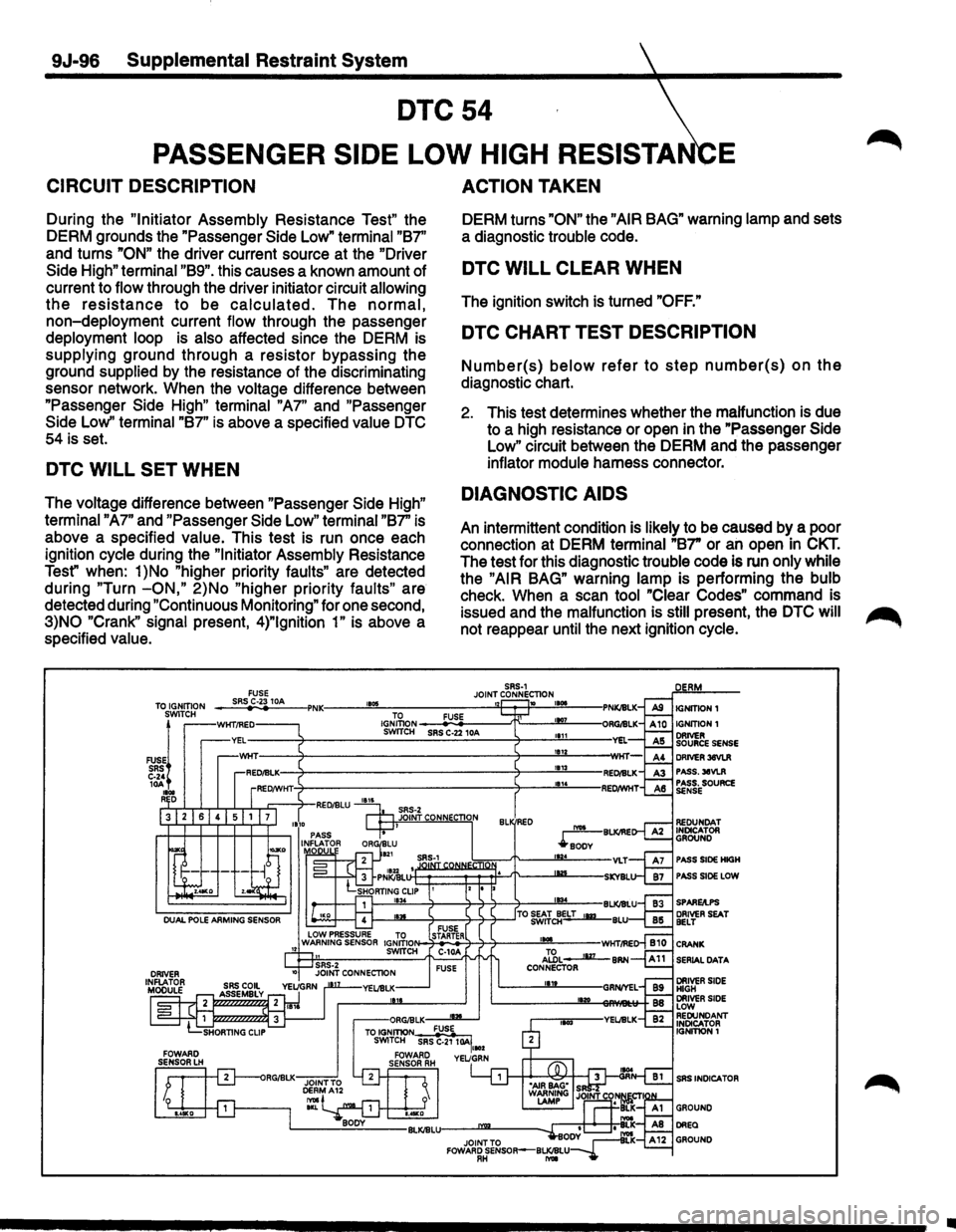
During the "Initiator Assembly Resistance Test" the
DERM grounds the "Passenger Side Low"
terminal "B7''
and turns
"ON" the driver current source at the "Driver
Side High" terminal "B9". this causes a known amount of
current to
flow through the driver initiator circuit allowing
the resistance to be calculated. The normal,
non-deployment current flow through the passenger
deployment loop is also affected since the DERM is
supplying ground through a resistor bypassing the
ground
supplied by the resistance of the discriminating
sensor network. When the
voltage difference between
"Passenger Side
High" terminal "A7" and "Passenger
Side Low''
terminal "B7" is above a specified value DTC
54 is set.
DTC WILL SET WHEN
The voltage difference between "Passenger Side High"
terminal "A7"
and "Passenger Side Low" terminal "B7" is
above a specified
value. This test is run once each
ignition
cycle during the "Initiator Assembly Resistance
Test" when:
1 )No "higher priority faults" are detected
during
"Turn -ON," 2)No "higher priority faults" are
detected during
"Continuous Monitoring" for one second,
3)NO "Crank" signal present, 4)"1gnition 1" is above a
specified
value.
ACTION TAKEN
DERM turns "ON" the "AIR BAG" warning lamp and sets
a diagnostic
trouble code.
DTC WILL CLEAR WHEN
The ignition switch is turned "OFF."
DTC CHART TEST DESCRIPTION
Number(s) below refer to step number(s) on the
diagnostic chart.
2. This test determines whether the malfunction is due
to a high resistance or open in the "Passenger Side
Low" circuit between the DERM and the passenger
inflator module harness connector.
DIAGNOSTIC AIDS
An intermittent condition is likely to be caused by a poor
connection at DERM
terminal "B7" or an open in CKT.
The test for this diagnostic trouble code is run only while
the "AIR BAG" warning lamp is performing the bulb
check. When a scan tool "Clear Codes" command is
issued and the
malfunction is still present, the DTC will ~
not reappear until the next ignition cycle.
SRS-1 JOINT CONNECTION 1105 1 10 TO FUSE IGNITION SWITCH SRS C-22 10A
PASS SIDE HIGH
PASS SIDE LOW
SERIAL
DATA
SRS INDICA TOR
•
Page 1726 of 1928
9J-102 Supplemental Restraint System
DTC62
REDUNDANT SRS INDICATOR CIRCUIT FAIL RE
CIRCUIT DESCRIPTION
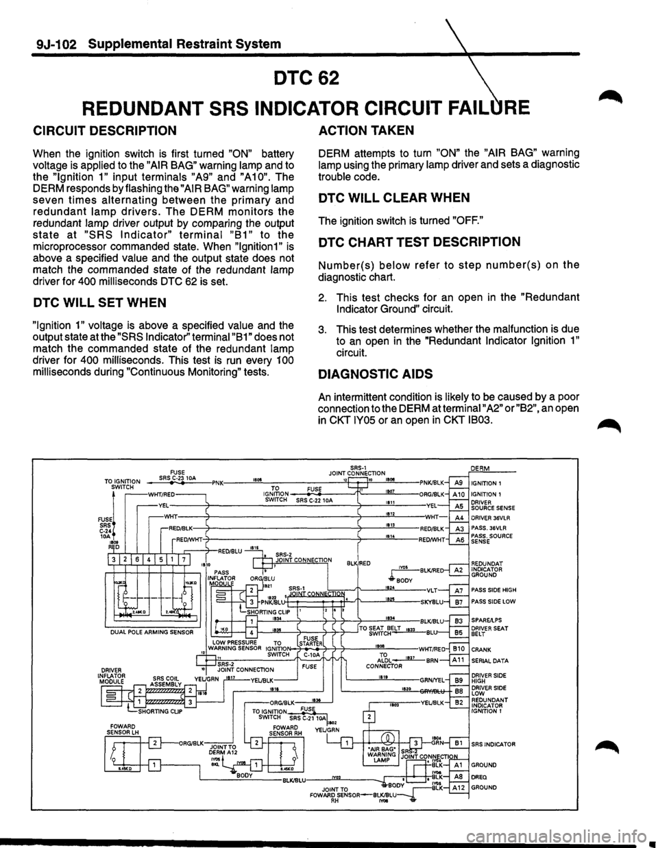
When the ignition switch is first turned "ON" battery
voltage is applied to the
"AIR BAG" warning lamp and to
the
"Ignition 1" input terminals "A9" and "A10". The
DERM responds by flashing the
"AIR BAG" warning lamp
seven
times alternating between the primary and
redundant lamp drivers. The DERM monitors the
redundant lamp driver output by comparing the output
state at "SRS Indicator" terminal "B1" to the
microprocessor commanded state. When
"lgnition1" is
above a specified value and the output state does not
match the commanded state of the redundant lamp
driver for
400 milliseconds DTC 62 is set.
DTC WILL SET WHEN
"Ignition 1" voltage is above a specified value and the
output state at the
"SRS Indicator'' terminal "B 1" does not
match the commanded state of the redundant lamp
driver for
400 milliseconds. This test is run every 100
milliseconds during "Continuous Monitoring" tests.
FUSE
ACTION TAKEN
DERM attempts to turn "ON" the "AIR BAG" warning
lamp using the primary lamp driver and sets a diagnostic
trouble code.
DTC WILL CLEAR WHEN
The ignition switch is turned "OFF."
DTC CHART TEST DESCRIPTION
Number(s) below refer to step number(s) on the
diagnostic chart.
2. This test checks for an open in the "Redundant
Indicator Ground"
circuit.
3. This test determines whether the malfunction is due
to
an open in the "Redundant Indicator Ignition 1"
circuit.
DIAGNOSTIC AIDS
An intermittent condition is likely to be caused by a poor
connection to the DERM at terminal
"A2" or "B2", an open
in
CKT IY05 or an open in CKT IB03.
SRS-1 JOINT CONNECTION ___ sR~SrC~·23~1_M ___ ,PNK:----~"~~------------~"~~~~18~~~--TO IGNITION SWITCH IGNITION 1
FUSE!
SRS C-24 lOA 1800 RED
WKT/RED IGJ~oN ---
PASS SIDE HIGH
PASS SIDE LOW
DRIVER SEAT BELT
CRANK
SERIAL DATA
DRIVER SIDE HIGH DRIVER SIDE LOW REDUNDANT INDICATOR
IGNITION 1
SRS INDICATOR
Page 1730 of 1928
9J-106 Supplemental Restraint System
DTC81
DRIVER IGNITION DIODE OPEN
CIRCUIT DESCRIPTION
During the "Turn-ON" tests, performed at the beginning
of each ignition
cycle, the DERM delays the charging of
the "Driver
3S VLR" and "Passenger 3S VLR" power
supplies. While the delay is active the DERM measures
the
voltage at the "Driver 3S VLR" terminal "A3", "Driver
Source
Sense" terminal "AS", and "Passenger Source
Sense" terminal "AS". When the voltage measured at the
two
"3S VLR" power supplies indicates they are in a
discharged state, the
voltage measured at "Passenger
Source
Sense" is within a specified range of "Ignition 1"
voltage
measured at "Driver Source Sense" is a specified
amount
below "Ignition 1" voltage DTC 81 is set.
DTC WILL SET WHEN
With both "3S VLR" power supplies in a discharged state,
the DERM detects
"Ignition 1" voltage at "Passenger
Source
Sense" terminal "AS" while simultaneously the
DERM detects
"Ignition 1" voltage at "Driver Source
Sense" terminal "AS". This test is run once each ignition
cycle during the "Turn-ON" tests while the "3S VLR
Delay"
is active.
ACTION TAKEN
DERM turns "ON" the "AIR BAG" warning lamp and sets
a diagnostic
trouble code.
DTC CHART TEST DESCRIPTION
Number(s) below refer to step number(s) on the
diagnostic chart.
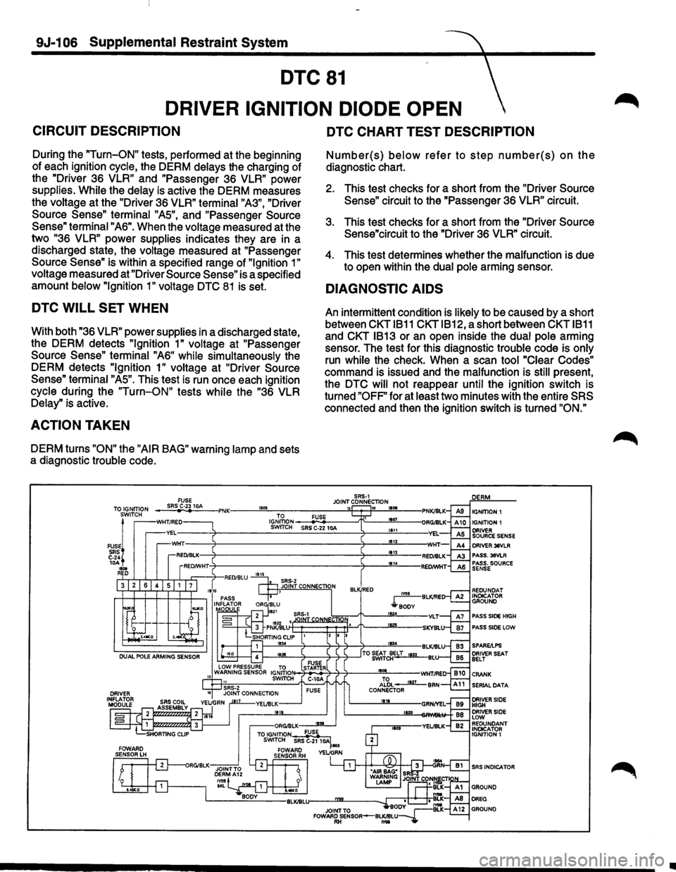
2. This test checks for a short from the "Driver Source
Sense" circuit to the "Passenger 3S VLR" circuit.
3. This test checks for a short from the "Driver Source
Sense"circuit to the "Driver
3S VLR" circuit.
4. This test determines whether the malfunction is due
to open within the
dual pole arming sensor.
DIAGNOSTIC AIDS
An intermittent condition is likely to be caused by a short
between
CKT 1811 CKTIB12, a short between CKT 1811
and CKT 1813 or an open inside the dual pole arming
sensor. The test for this diagnostic
trouble code is only
run while the check. When a scan tool "Clear Codes"
command is issued and the malfunction is still present,
the
DTC will not reappear until the ignition switch is
turned
"OFF" for at least two minutes with the entire SRS
connected and then the ignition switch is turned "ON."
SRS-1 FUSE JOINT CONNECTION TOS~~~:?N -_;:,;SR-"
IGNmON ~-=-------"T"---""'1107<----SWrTCH SRS C-22 10A 1111
1112 DRIVER 36VLR PASS.36VLR PASS. SOURCE SENSE
REOUNOAT INDICATOR GROUND
PASS SIDE HIGH
PASS SIDE LOW
SERIAL DATA
SRS INDICATOR
•
Page 1741 of 1928
Supplemental Restraint System 9J-117
SERVICE PRECAUTIONS
CAUTION: WHEN PERFORMING SERVICE ON OR
AROUND SRS COMPONENTS OR SRS WIRING,
FOLLOW
THE PROCEDURES LISTED BELOW TO
TEMPORARILY
DISABLE THE SRS. FAILURE TO
FOLLOW PROCEDURES COULD RESULT IN
POSSIBLE AIR BAG DEPLOYMENT, PERSONAL
INJURY OR OTHERWISE UNNEEDED SRS
REPAIRS.
The DERM in Driver-Passenger SRS can maintain
sufficient voltage to cause a deployment for up to 2
minutes after the ignition switch is turned to
"OFF," the
battery is disconnected, or the fuse powering the DERM
is removed.
Many of the service procedures require removal of the
"AIR BAG" fuse, and disconnection of the inflator
modules from the deployment loop to avoid an accidental
deployment.
If the inflator module is disconnected from
the deployment loop as noted in the "Disabling the
SRS"
procedure that follows, service can begin immediately
without waiting for the 2 minute time period to expire.
DISABLING THE SRS
REMOVAL
• Turn the steering wheel so that the vehicle's wheels
are pointing straight ahead.
• Turn the ignition switch to "OFF"
1. Remove SRS fuse C-21, C-22, C-23 and C-24 from
left dash side lower fuse block.
2. Disconnect yellow
3-way connector at the base of
the steering column.
3. Remove
liP compartment door assembly, Refer to
"Passenger inflator module replacemenf' in section
9J-135.
4. Disconnect yellow 4-way connector behind the liP
compartment door assembly.
NOTE
• With the" AIR BAG" fuse removed and ignition switch
"ON," the "AiR BAG" warning lamp will be "ON." This
is normal operation and does not indicate
an SRS
malfunction.
ENABLING THE SRS
INSTALLATION
Turn ignition switch to "LOCK" and remove key.
1. Connect yellow 4-way connector of passenger
inflator module.
2. Install liP compartment door assembly, Refer to
"Passenger inflator module replacement" in section
9J-3.
3. Connect yellow 3-way connector at the base of the
steering column.
4. Install" AIR BAG" fuse C-21, C-22, C-23 and C-24 to
left dash side lower fuse block.
Tum ignition switch to
"RUN" and verify that the "AIR
BAG"
warning lamp flashes seven times and then turns
"OFF" If it does not operate as described, perform the
"SRS Diagnostic System Check" in section 9J-32.
HANDLING/INSTALLATION/DIAGNOSIS
1. Inflator modules should not be subjected to
temperatures above 65°C(150°F).
2. Discriminating s~nsors, inflator modules, arming
sensors, or DERMs should not be used if they have
been dropped from a height of 1
00 centimeters (3.28
feet) or more.
3. When a discriminating sensor or arming sensor is
replaced, it MUST be oriented with the arrow
on the
sensor pointing toward the front of the vehicle.
It is
very important for the discriminating sensors and
arming sensor to be located flat on the mounting
surface, parallel to the vehicle datum line.
It is
important that the sensor mounting surface is free of
any dirt or other foreign material.
4. Do not apply power to the SRS unless all
components are connected or a diagnostic chart
requests it, as this
will set a diagnostic trouble code.
5. The
"SRS Diagnostic System Check'' must be the
starting point of any SRS diagnostics. The
"SRS
Diagnostic System Check" will verify proper "AIR
BAG" warning lamp operation and will lead you to the
correct chart to diagnose any SRS malfunctions.
Bypassing these procedures may result in extended
diagnostic time, incorrect diagnosis, and incorrect
parts replacements.
INSPECTIONS REQUIRED AFTER ACCI
DENT
CAUTION: CERTAIN SRS COMPONENTS MUST BE
REPLACED AFTER A FRONTAL
CRASH INVOLVING
AIR
BAG DEPLOYMENT.
In all types of accident regardless of "Air Bag"
deployment, visually inspect all the following
components and their points and replace as required:
- Passenger
Inflator Module
- Steering wheel
- SRS coil assembly
- Steering column
- Knee bolster and
Instrument panel mounting