tires ISUZU TROOPER 1995 Service Manual
[x] Cancel search | Manufacturer: ISUZU, Model Year: 1995, Model line: TROOPER, Model: ISUZU TROOPER 1995Pages: 1928
Page 253 of 1928
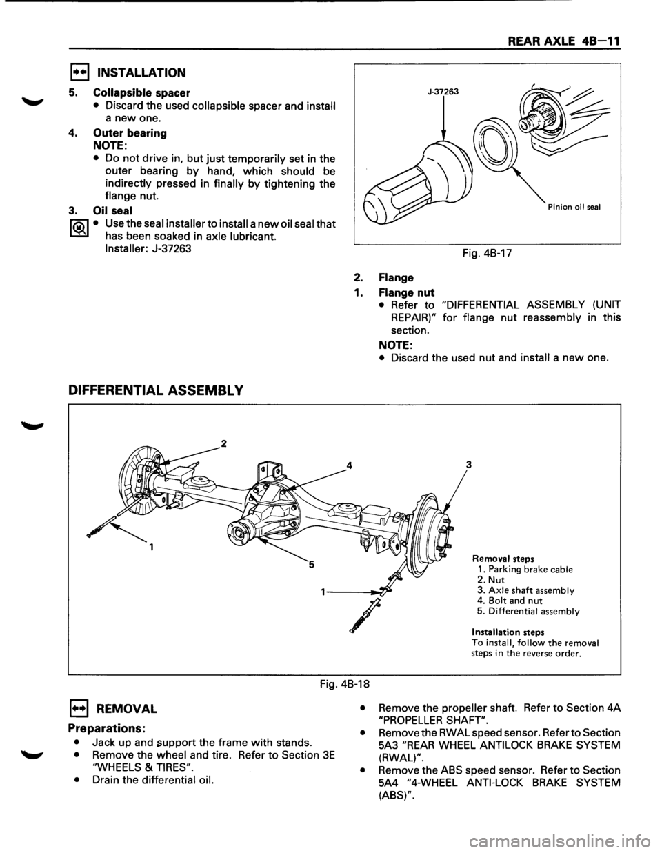
E) INSTALLATION
5. Collapsible spacer
• Discard the used collapsible spacer and install
a new one.
4. Outer bearing
NOTE:
• Do not drive in, but just temporarily set in the
outer bearing
by hand, which should be
indirectly pressed in finally by tightening the
flange nut.
3. Oil seal
1"?.:\1 • Use the seal installer to install a new oil seal that
l.::::'i:il has been soaked in axle lubricant.
Installer:
J-37263
DIFFERENTIAL ASSEMBL V
~ 1
REAR AXLE 48-11
J-37263
Pinion oil seal
Fig. 4B-17
2. Flange
1. Flange nut
• Refer to "DIFFERENTIAL ASSEMBLY (UNIT
REPAIR)" for flange nut reassembly in this
section.
NOTE:
• Discard the used nut and install a new one.
3
/
Removal steps
1. Parking brake cable
2. Nut 3. Axle shaft assembly 4. Bolt and nut 5. Differential assembly
Installation
steps
To install, follow the removal steps in the reverse order.
Fig. 4B-18
E) REMOVAL
Preparations:
• Jack up and .support the frame with stands.
• Remove the wheel and tire. Refer to Section 3E
"WHEELS & TIRES".
•
Drain the differential oil. •
Remove
the propeller shaft. Refer to Section 4A
"PROPELLER SHAFT".
•
Remove the RWAL speed sensor. Refer to Section
5A3
"REAR WHEEL ANTILOCK BRAKE SYSTEM
(RWAL)".
•
Remove the ABS speed sensor. Refer to Section
5A4
"4-WHEEL ANTI-LOCK BRAKE SYSTEM
(ABS)".
Page 280 of 1928
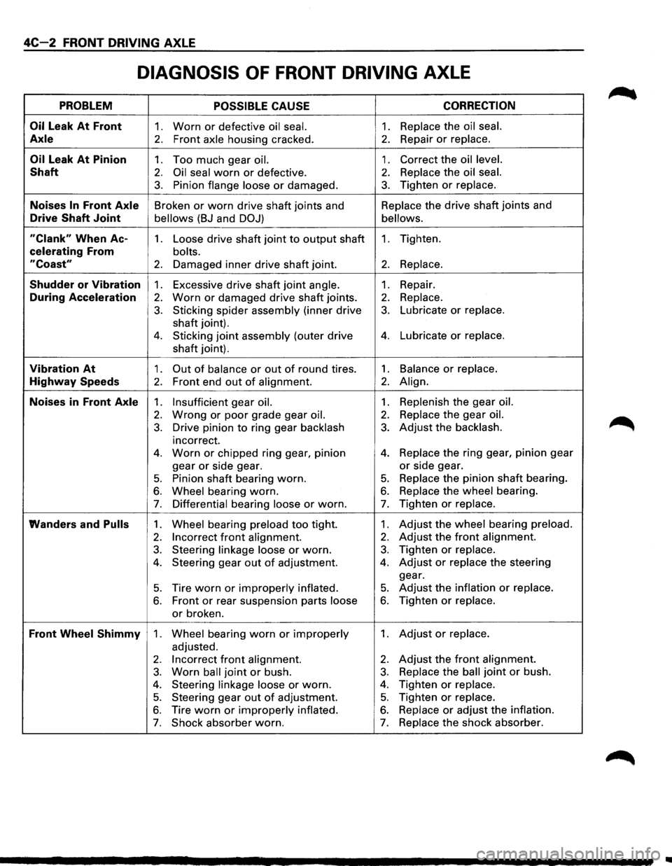
4C-2 FRONT DRIVING AXLE
DIAGNOSIS OF FRONT DRIVING AXLE
PROBLEM POSSIBLE CAUSE CORRECTION
Oil
Leak At Front 1. Worn or defective oil seal. 1. Replace the oil seal.
Axle 2. Front axle housing cracked. 2. Repair or replace.
Oil Leak At Pinion 1. Too much gear oil. 1. Correct the oil level.
Shaft 2. Oil seal worn or defective. 2. Replace the oil seal.
3. Pinion flange loose or damaged. 3. Tighten or replace.
Noises In Front Axle Broken or worn drive shaft joints and Replace
the drive shaft joints and
Drive Shaft Joint bellows (BJ and DOJ) bellows.
"Clank" When Ac-1. Loose drive shaft joint to output shaft 1. Tighten.
celerating From bolts.
"Coast" 2. Damaged inner drive shaft joint. 2. Replace.
Shudder or Vibration 1. Excessive drive shaft joint angle. 1. Repair.
During Acceleration 2. Worn or damaged drive shaft joints. 2. Replace.
3. Sticking spider assembly (inner drive 3. Lubricate or replace.
shaft joint).
4. Sticking joint assembly (outer drive 4. Lubricate or replace.
shaft joint).
Vibration At 1. Out of balance or out of round tires. 1. Balance or replace.
Highway Speeds 2. Front end out of alignment. 2. Align.
Noises in Front Axle 1. Insufficient gear oil. 1. Replenish the gear oil.
2. Wrong or poor grade gear oil. 2. Replace the gear oil.
3. Drive pinion to ring gear backlash 3. Adjust the backlash.
incorrect.
4. Worn or chipped ring gear, pinion 4. Replace the ring gear, pinion gear
gear
or side gear. or side gear.
5. Pinion shaft bearing worn. 5. Replace the pinion shaft bearing.
6. Wheel bearing worn. 6. Replace the wheel bearing.
7. Differential bearing loose or worn. 7. Tighten or replace.
Wanders and Pulls 1. Wheel bearing preload too tight. 1. Adjust the wheel bearing preload.
2. Incorrect front alignment. 2. Adjust the front alignment.
3. Steering linkage loose or worn. 3. Tighten or replace.
4. Steering gear out of adjustment. 4. Adjust or replace the steering
gear.
5. Tire worn or improperly inflated. 5. Adjust the inflation or replace.
6. Front or rear suspension parts loose 6. Tighten or replace.
or broken.
Front Wheel Shimmy 1. Wheel bearing worn or improperly 1. Adjust or replace.
adjusted.
2. Incorrect front alignment. 2. Adjust the front alignment.
3. Worn ball joint or bush. 3. Replace the ball joint or bush.
4. Steering linkage loose or worn. 4. Tighten or replace.
5. Steering gear out of adjustment. 5. Tighten or replace.
6. Tire worn or improperly inflated. 6. Replace or adjust the inflation.
7. Shock absorber worn. 7. Replace the shock absorber.
..
Page 322 of 1928
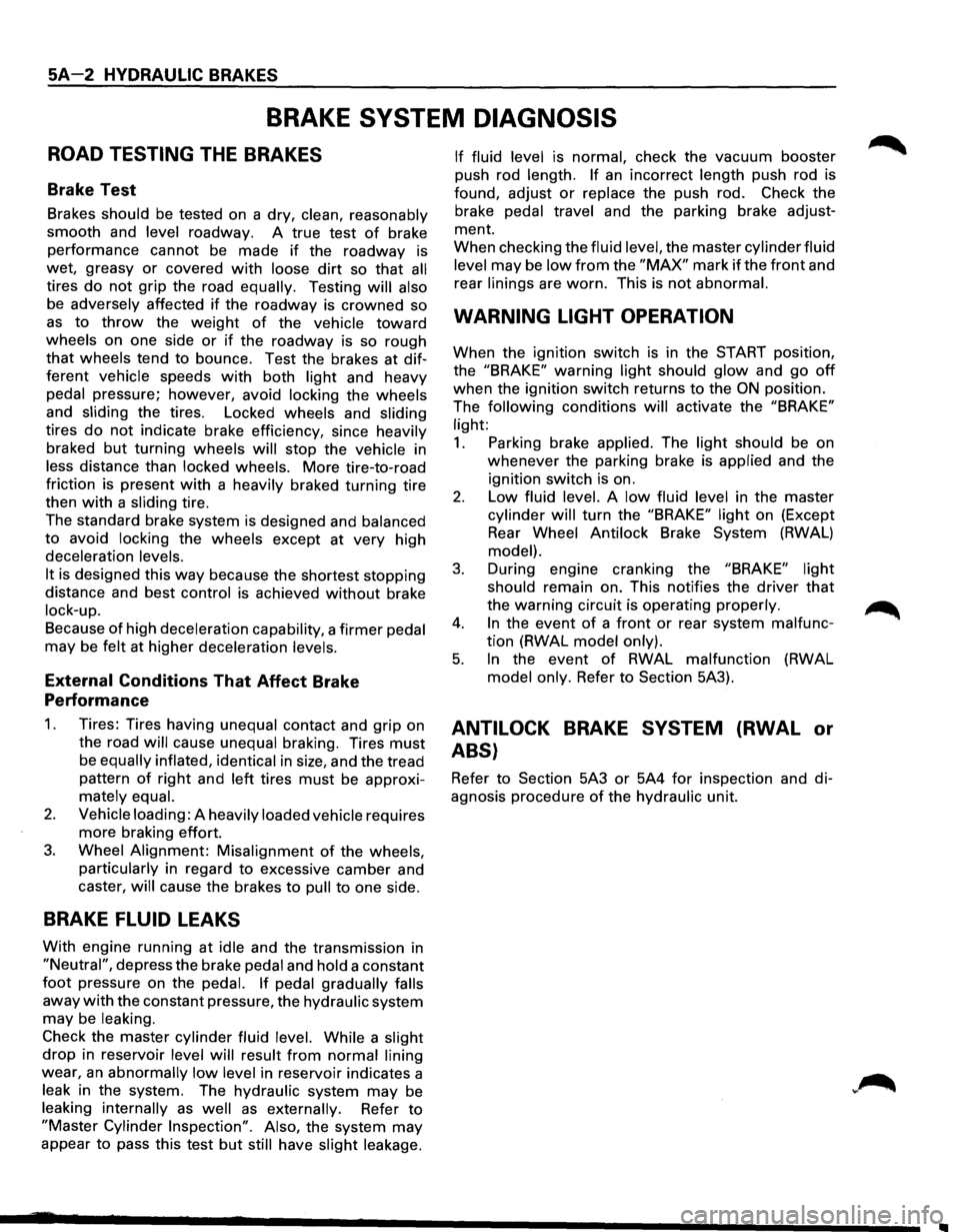
SA-2 HYDRAULIC BRAKES
BRAKE SYSTEM DIAGNOSIS
ROAD TESTING THE BRAKES
Brake Test
Brakes should be tested on a dry, clean, reasonably
smooth and
level roadway. A true test of brake
performance cannot be made
if the roadway is
wet, greasy
or covered with loose dirt so that all
tires do not grip the road equally. Testing will also
be adversely affected if the roadway is crowned so
as to throw the weight of the vehicle toward
wheels on one side or if the roadway is so rough
that wheels tend to bounce. Test the brakes at dif
ferent vehicle speeds with both light and heavy
pedal pressure; however, avoid locking the wheels
and sliding the tires. Locked wheels and sliding
tires do not indicate brake efficiency, since heavily
braked but turning wheels will stop the vehicle in
less distance than locked wheels. More tire-to-road
friction is present
with a heavily braked turning tire
then
with a sliding tire.
The standard brake system is designed and
balanced
to avoid locking the wheels except at very high
deceleration
levels.
It
is designed this way because the shortest stopping
distance and best
control is achieved without brake
lock-up.
Because of high deceleration capability, a firmer pedal
may be felt at higher deceleration levels.
External Conditions That Affect Brake
Performance
1.
2.
3.
Tires: Tires having unequal contact and grip on
the road
will cause unequal braking. Tires must
be equally inflated, identical in size, and the tread
pattern
of right and left tires must be approxi
mately equal.
Vehicle loading:
A heavily loaded vehicle requires
more braking effort.
Wheel Alignment: Misalignment of the wheels,
particularly
in regard to excessive camber and
caster,
will cause the brakes to pull to one side.
BRAKE FLUID LEAKS
With engine running at idle and the transmission in
"Neutral", depress the brake pedal and hold a constant
foot pressure on the pedal. If pedal gradually falls
away with the constant pressure, the hydraulic system
may be leaking.
Check the master cylinder fluid level. While a slight
drop in reservoir level will result from normal lining
wear, an abnormally low level in reservoir indicates a
leak in the system. The hydraulic system may be
leaking internally as well as externally. Refer to
"Master Cylinder Inspection". Also, the system may
appear
to pass this test but still have slight leakage. If
fluid level
is normal, check the vacuum booster
push rod
length. If an incorrect length push rod is
found, adjust
or replace the push rod. Check the
brake
pedal travel and the parking brake adjust
ment.
When checking the
fluid level, the master cylinder fluid
level
may be low from the "MAX" mark if the front and
rear
linings are worn. This is not abnormal.
WARNING LIGHT OPERATION
When the ignition switch is in the START position,
the
"BRAKE" warning light should glow and go off
when the ignition switch returns to the ON position.
The
following conditions will activate the "BRAKE"
light:
1. Parking brake applied. The light should be on
whenever the parking brake is applied and the
ignition switch is on.
2. Low fluid level. A low fluid level in the master
cylinder will turn the "BRAKE" light on (Except
Rear
Wheel Antilock Brake System (RWAL)
model).
3. During engine cranking the "BRAKE" light
should
remain on. This notifies the driver that
the warning circuit is operating properly.
4. In the event of a front or rear system malfunc
tion (RWAL model only).
5. In the event of RWAL malfunction (RWAL
model only. Refer to Section 5A3).
ANTILOCK BRAKE SYSTEM (RWAL or
ABS}
Refer to Section 5A3 or 5A4 for inspection and di
agnosis procedure of the hydraulic unit.
..
Page 323 of 1928
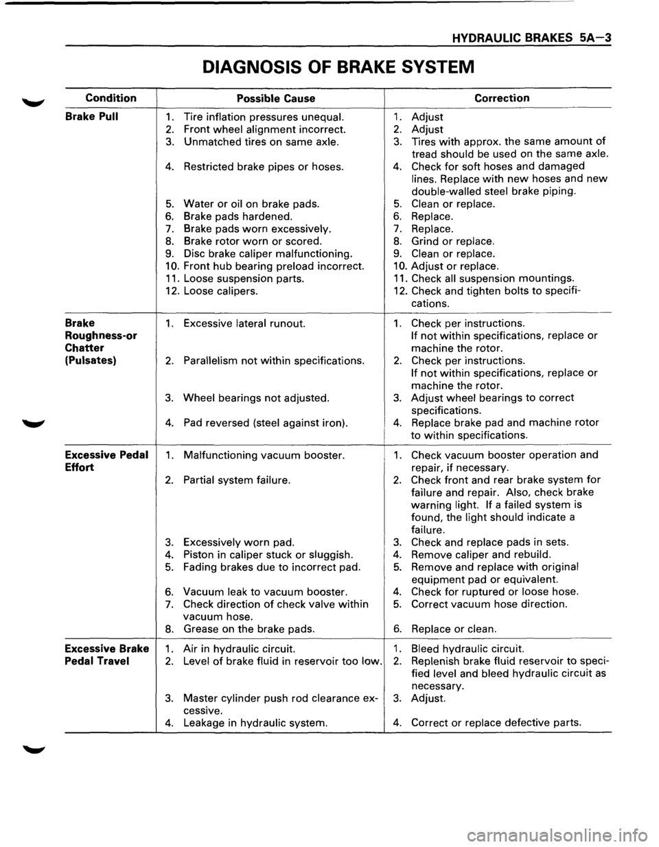
HYDRAULIC BRAKES 5A-3
DIAGNOSIS OF BRAKE SYSTEM
Condition
Possible Cause Correction
Brake
Pull 1. Tire inflation pressures unequal. 1. Adjust
2. Front wheel alignment incorrect. 2. Adjust
3. Unmatched tires on same axle. 3. Tires with approx. the same amount of
tread should be used on the same axle.
4. Restricted brake pipes or hoses. 4. Check for soft hoses and damaged
lines. Replace with new hoses and new
double-walled steel brake piping.
5. Water or oil on brake pads. 5. Clean or replace.
6. Brake pads hardened. 6. Replace.
7. Brake pads worn excessively. 7. Replace.
8. Brake rotor worn or scored. 8. Grind or replace.
9. Disc brake caliper malfunctioning. 9. Clean or replace.
10. Front hub bearing preload incorrect. 10. Adjust or replace.
11. Loose suspension parts. 11. Check all suspension mountings.
12. Loose
calipers. 12. Check and tighten bolts to specifi-
cations.
Brake 1. Excessive lateral runout. 1. Check per instructions.
Roughness-or If not within specifications, replace or
Chatter machine the rotor.
(Pulsates) 2. Parallelism not within specifications. 2. Check per instructions.
If not within specifications, replace or
machine the rotor.
3. Wheel bearings not adjusted. 3. Adjust wheel bearings to correct
specifications.
4. Pad reversed (steel against iron). 4. Replace brake pad and machine rotor
to within specifications.
Excessive Pedal 1. Malfunctioning vacuum booster. 1. Check vacuum booster operation and
Effort repair, if necessary.
2. Partial system failure. 2. Check front and rear brake system for
failure and repair. Also, check brake
warning
light. If a failed system
is
found, the
light should indicate a
failure.
3. Excessively worn pad. 3. Check and replace pads in sets.
4. Piston in caliper stuck or sluggish. 4. Remove caliper and rebuild.
5. Fading brakes due to incorrect pad. 5. Remove and replace with original
equipment pad or equivalent.
6. Vacuum leak to vacuum booster. 4. Check for ruptured or loose hose.
7. Check direction of check valve within 5. Correct vacuum hose direction.
vacuum hose.
8. Grease on the brake pads. 6. Replace or clean.
Excessive Brake 1. Air in hydraulic circuit. 1. Bleed hydraulic circuit.
Pedal Travel 2. Level of brake fluid in reservoir too low. 2. Replenish brake fluid reservoir to speci-
fied
level and bleed hydraulic circuit as
necessary.
3. Master cylinder push rod clearance ex-3. Adjust.
cessive.
4. Leakage in hydraulic system. 4. Correct or replace defective parts.
Page 353 of 1928
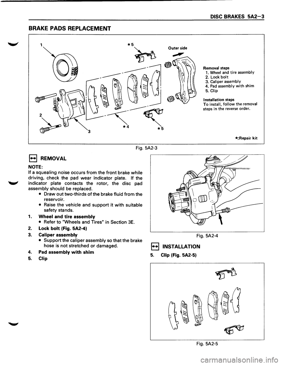
BRAKE PADS REPLACEMENT
1 Outer side
2
DISC BRAKES 5A2-3
Removal steps
1. Wheel and tire assembly
2. Lock
bolt 3. Caliper assembly
4. Pad assembly with shim
5. Clip
Installation
steps To install, follow the removal
steps in the reverse order.
*;Repair kit
Fig. 5A2-3
1••1 REMOVAL
NOTE:
If a squealing noise occurs from the front brake while
driving, check the pad wear indicator plate. If the
........., indicator plate contacts the rotor, the disc pad
assembly should be replaced.
•
Draw out two-thirds of the brake fluid from the
reservoir.
• Raise the vehicle and support it with suitable
safety stands.
1. Wheel and tire assembly
•
Refer to "Wheels and Tires" in Section 3E.
2. Lock bolt (Fig. 5A2-4)
3. Caliper assembly
• Support
the caliper assembly so that the brake
hose
is not stretched or damaged.
4. Pad assembly with shim
5. Clip
Fig. 5A2-4
1••1 INSTALLATION
5. Clip (Fig. 5A2-5)
Fig. 5A2-5
Page 354 of 1928
5A2-4 DISC BRAKES
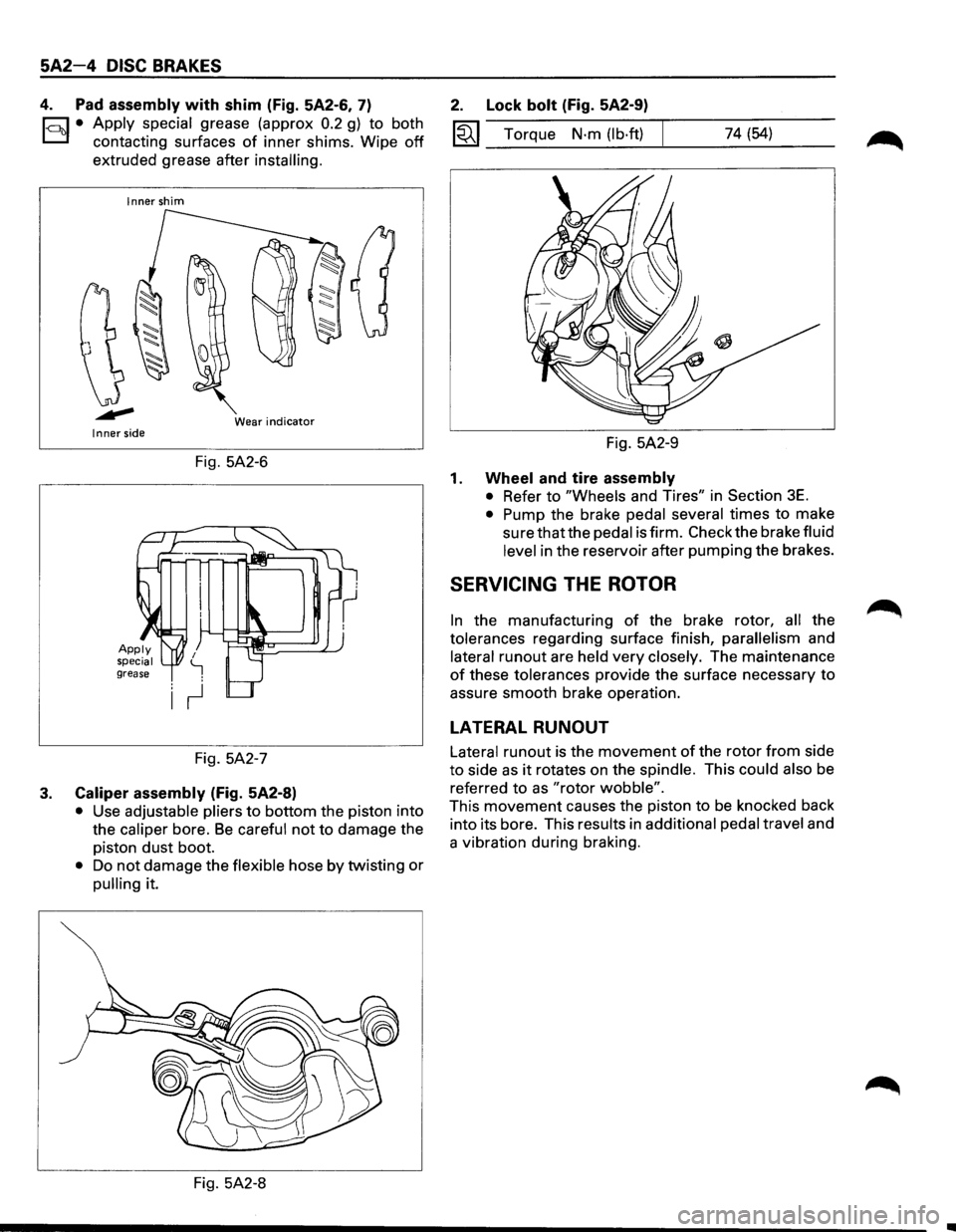
4. Pad assembly with shim (Fig. 5A2-6, 7)
1-c::~t:.l• Apply ~pecial grease (approx 0.2 g) to both
contactmg surfaces
of inner shims. Wipe off
extruded grease after installing.
Inner shim
Wear
indicator Inner side
Fig. 5A2-6
Fig. 5A2-7
3. Caliper assembly (Fig. 5A2-8)
• Use adjustable pliers to bottom the piston into
the
caliper bore. Be careful not to damage the
piston
dust boot.
• Do not damage the flexible hose by twisting or
pulling it.
Fig. 5A2-8
2. Lock bolt (Fig. 5A2-9)
1«1 Torque N·m (lb·ft) 74 (54)
Fig. 5A2-9
1. Wheel and tire assembly
• Refer to "Wheels and Tires" in Section 3E.
• Pump the brake pedal several times to make
sure that the pedal is firm. Check the brake fluid
level in the reservoir after pumping the brakes.
SERVICING THE ROTOR
In the manufacturing of the brake rotor, all the
tolerances regarding surface finish,
parallelism and
lateral
runout are held very closely. The maintenance
of these tolerances provide the surface necessary to
assure smooth brake operation.
LATERAL RUNOUT
Lateral runout is the movement of the rotor from side
to side as it rotates on the spindle. This could also be
referred
to as "rotor wobble".
This movement causes the piston to be knocked back
into its bore. This results in
additional pedal travel and
a vibration during braking.
Page 358 of 1928
5A2-1 0 DISC BRAKES
REAR DISC BRAKE
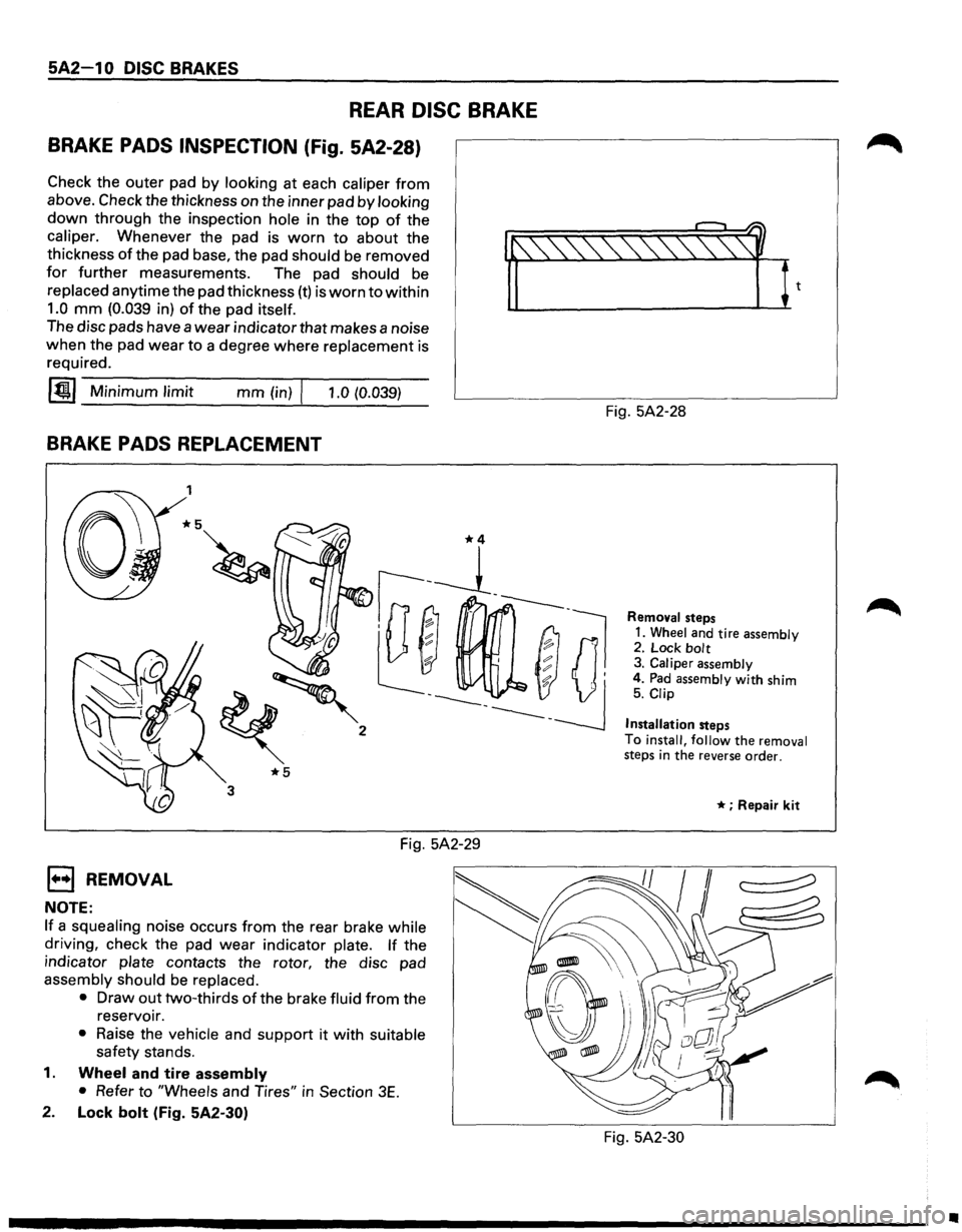
BRAKE PADS INSPECTION (Fig. 5A2-28)
Check the outer pad by looking at each caliper from
above. Check the thickness on the inner pad by looking
down through the inspection hole in the top of the
caliper. Whenever the pad is worn to about the
thickness
of the pad base, the pad should be removed
for further measurements. The pad should be
replaced anytime the pad thickness (t) is worn to within
1.0 mm (0.039 in) of the pad itself. 'f'-~1~
The disc pads have a wear indicator that makes a noise
when the pad wear to a degree where replacement is
required.
~~~-M--in-im __ u_m_l-im--it _____ m_m--(i-n)-rl--,-.-0-(0-.-03_9_) ___
BRAKE PADS REPLACEMENT
EJ REMOVAL
NOTE:
1
*5
3
Fig. 5A2-29
If a squealing noise occurs from the rear brake while
driving, check the pad wear indicator plate. If the
indicator
plate contacts the rotor, the disc pad
assembly should be replaced.
•
Draw out two-thirds of the brake fluid from the
reservoir.
• Raise the vehicle and support it with suitable
safety stands.
1. Wheel and tire assembly
•
Refer to "Wheels and Tires" in Section 3E.
2. Lock bolt (Fig. 5A2-30) Fig.
5A2-28
Removal steps
1. Wheel and tire assembly 2. Lock bolt 3. Caliper assembly
4. Pad assembly with shim 5. Clip
Installation
steps
To
install, follow the removal steps in the reverse order.
* ; Repair kit
Fig. 5A2-30
•
Page 360 of 1928
5A2-12 DISC BRAKES
1. Wheel and tire assembly
• Refer to "Wheels and Tires" in Section 3E.
• Pump the brake pedal several times to
make sure that the pedal
is firm. Check the
brake fluid level in the reservoir after
pumping the brakes.
SERVICING THE ROTOR
In the manufacturing of the brake rotor, all the
tolerances regarding surface finish, parallelism and
lateral runout are held very closely. The maintenance
of these tolerances provide the surface necessary to
assure smooth brake operation.
LATERAL RUNOUT
Lateral runout is the movement of the rotor from side
to side as it rotates on the spindle. This could also be
referred
to as "rotor wobble".
This movement causes the piston to be knocked back
into its bore. This
results in additional pedal travel and
a vibration during braking.
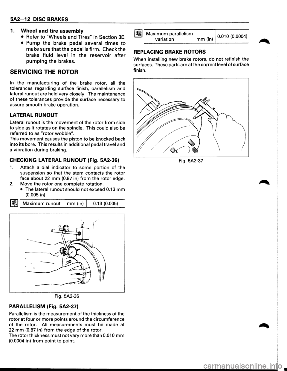
CHECKING LATERAL RUNOUT (Fig. 5A2-36)
1. Attach a dial indicator to some portion of the
suspension so
that the stem contacts the rotor
face about 22 mm (0.87 in) from the rotor edge.
2. Move the rotor one complete rotation.
• The lateral runout should not exceed 0.13 mm
(0.005 in)
~~~ Maximum runout mm (in) I 0.13 (0.005)
Fig. 5A2-36
PARALLELISM (Fig. 5A2-37)
Parallelism is the measurement of the thickness of the
rotor at
four or more points around the circumference
of the rotor. All measurements must be made at
22 mm (0.87 in) from the edge of the rotor.
The rotor thickness
must not vary more than 0.010 mm
(0.0004 in) from point to point.
Maximum parallelism variation mm (in) 0
·01 0 (0.000 4
)
REPLACING BRAKE ROTORS
When installing new brake rotors, do not refinish the
surfaces. These parts are at the correct
level of surface
finish.
Fig. 5A2-37
Page 362 of 1928
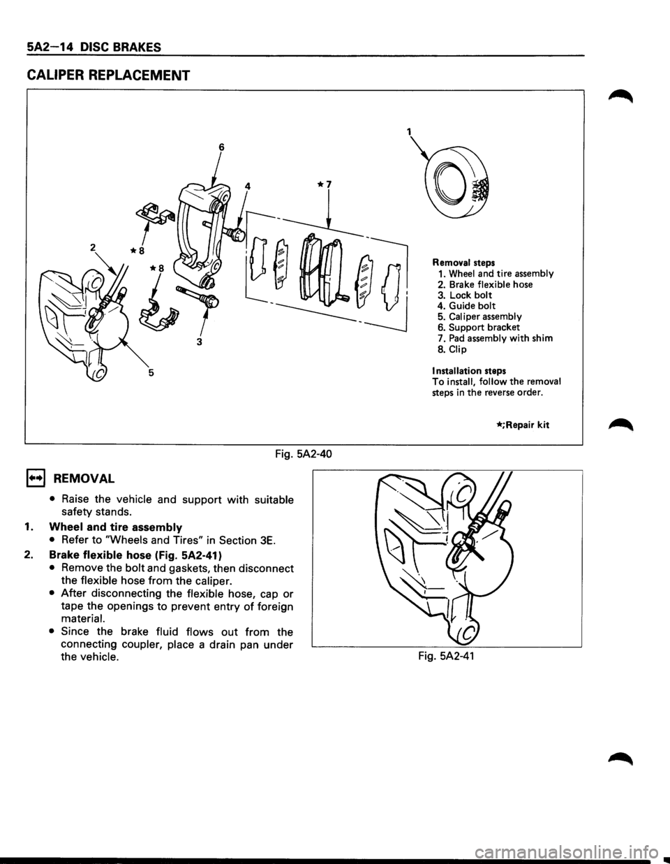
5A2-14 DISC BRAKES
CALIPER REPLACEMENT
6
3
Fig. 5A2-40
1••1 REMOVAL
• Raise the vehicle and support with suitable
safety stands.
1. Wheel and tire assembly
• Refer to "Wheels and Tires" in Section 3E.
2. Brake flexible hose (Fig. 5A2-41)
• Remove the bolt and gaskets, then disconnect
the flexible hose
from the caliper.
• After disconnecting the flexible hose, cap or
tape the openings to prevent entry of foreign
material.
• Since the brake fluid flows out from the
connecting
coupler, place a drain pan under
the
vehicle.
1
Removal steps
1. Wheel and tire assembly
2. Brake flexible hose
3. Lock bolt 4. Guide bolt 5. Caliper assembly 6. Support bracket
7.
Pad assembly with shim
8.
Clip
Installation
steps
To install, follow the removal steps in the reverse order.
*;Repair kit
Fig. 5A2-41
Page 364 of 1928
5A2-16 DISC BRAKES
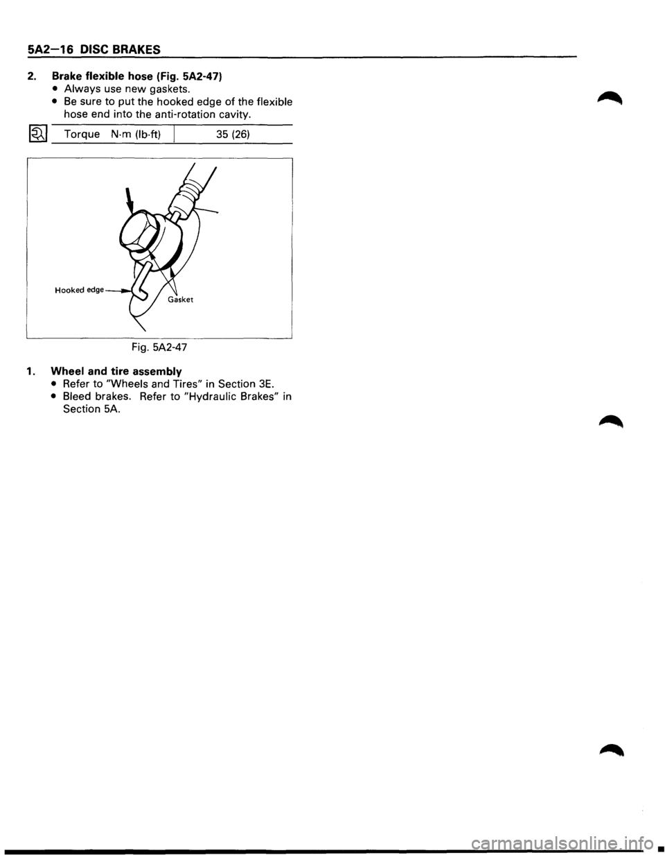
2. Brake flexible hose (Fig. 5A2-47)
• Always use new gaskets.
• Be sure to put the hooked edge of the flexible
hose end into the anti-rotation cavity.
~~~ Torque N-m (lb·ft) 35 (26)
Hooked edge
Fig. 5A2-47
1. Wheel and tire assembly
• Refer to "Wheels and Tires" in Section 3E.
• Bleed brakes. Refer to "Hydraulic Brakes" in
Section 5A.
•