tires ISUZU TROOPER 1995 Owner's Manual
[x] Cancel search | Manufacturer: ISUZU, Model Year: 1995, Model line: TROOPER, Model: ISUZU TROOPER 1995Pages: 1928
Page 174 of 1928
3C-1 0 FRONT SUSPENSION
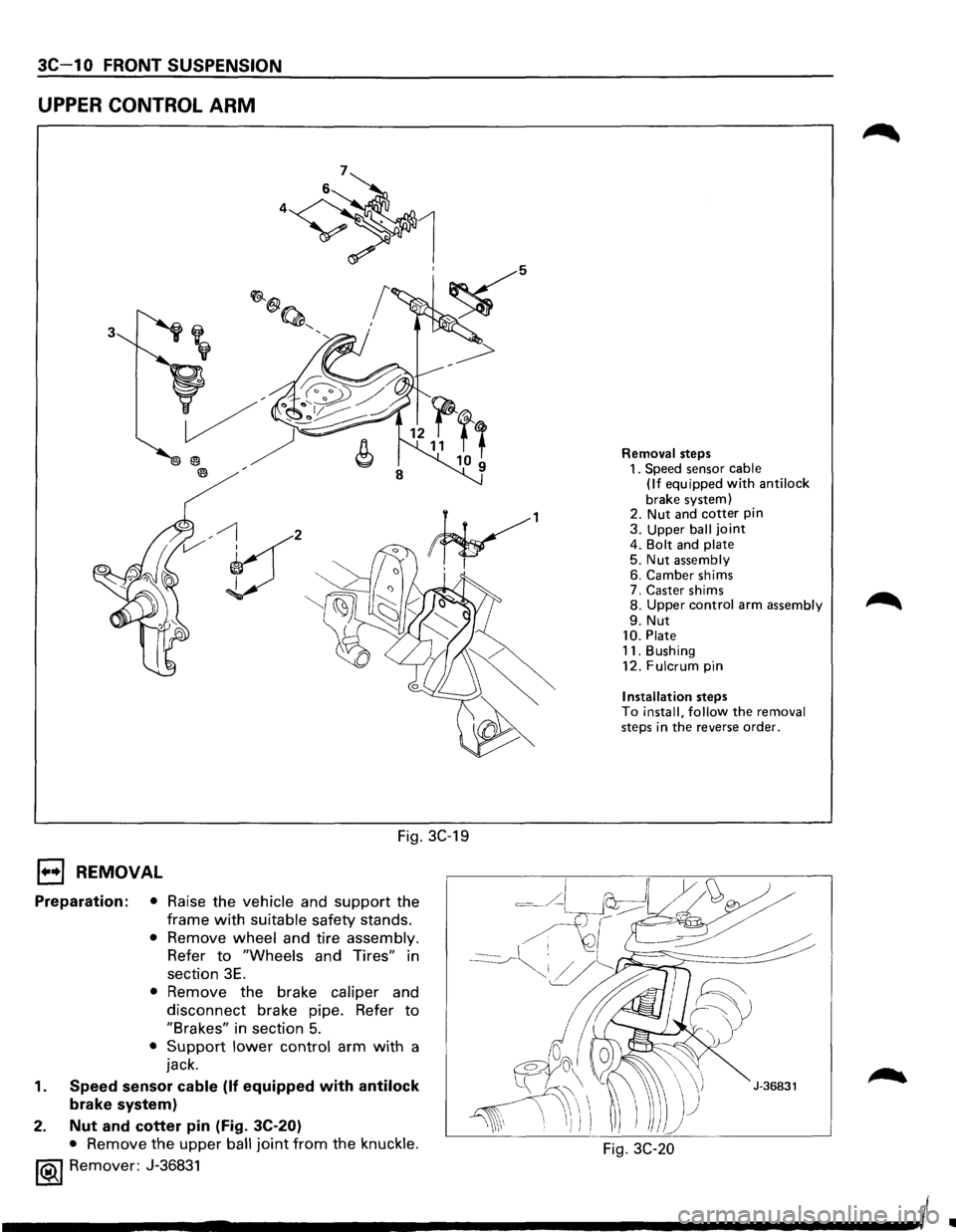
UPPER CONTROL ARM
3
V' , I
Fig. 3C-19
1••1 REMOVAL
Preparation: • Raise the vehicle and support the
frame
with suitable safety stands.
• Remove wheel and tire assembly.
Refer
to "Wheels and Tires" in
section
3E.
• Remove the brake caliper and
disconnect brake pipe. Refer
to
"Brakes" in section 5.
• Support lower control arm with a
jack.
1. Speed sensor cable (If equipped with antilock
brake system)
2.
Nut and cotter pin (Fig. 3C-20)
• Remove the upper ball joint from the knuckle.
1®.1 Remover: J-36831
Removal steps 1. Speed sensor cable
(If equipped with anti lock
brake system)
2. Nut and cotter pin 3. Upper ball joint 4. Bolt and plate 5. Nut assembly 6. Camber shims
7. Caster shims
8.
Upper control arm assembly
9. Nut 10. Plate 11. Bushing
12. Fulcrum pin
Installation steps To install, follow the removal steps in the reverse order.
Fig. 3C-20
Ill
Page 177 of 1928
FRONT SUSPENSION 3C-13
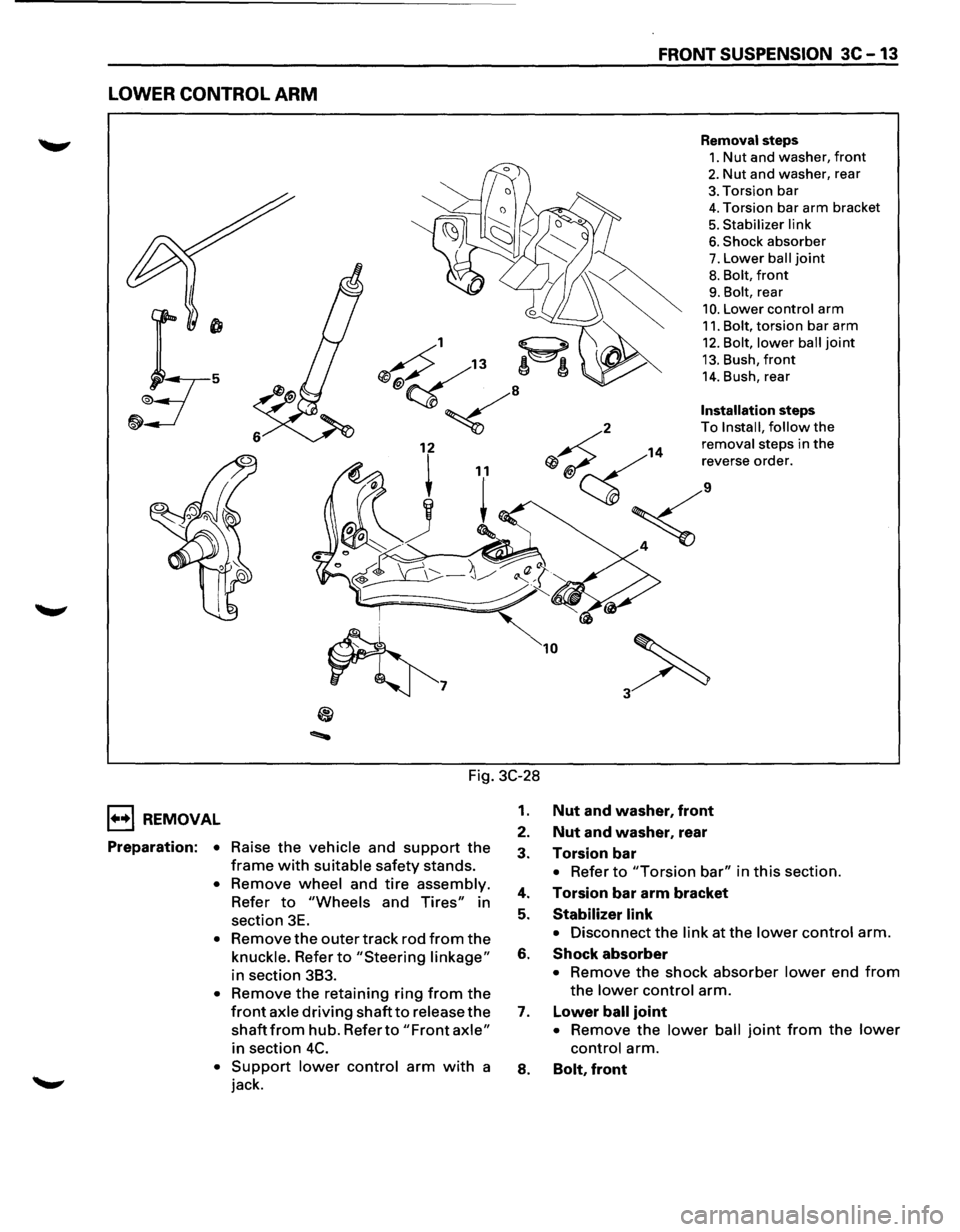
LOWER CONTROL ARM
Removal steps
1. Nut and washer, front
2. Nut and washer, rear
3. Torsion bar
4. Torsion bar arm bracket
5. Stabilizer link
6. Shock absorber
7. Lower ball joint
8. Bolt, front
9. Bolt, rear
10. Lower control arm
11. Bolt, torsion bar arm
12. Bolt, lower ball joint
13. Bush, front
14. Bush, rear
Installation steps
2 To
Install, follow the
14
removal steps in the
Qj ~ ';ve"'e mde,.
;<
~7
10
Fig. 3C-28
1••1 REMOVAL
Preparation: • Raise the vehicle and support the
frame with suitable safety stands.
• Remove wheel and tire assembly.
Refer to "Wheels and Tires" in
section 3E.
• Remove the outer track rod from the
knuckle. Refer to "Steering linkage"
in section 383.
• Remove the retaining ring from the
front axle driving shaft to release the
shaft from hub. Refer to "Front axle"
in section 4C.
• Support lower control arm with a
jack.
1. Nut and washer, front
2. Nut and washer, rear
3. Torsion bar
• Refer to "Torsion bar" in this section.
4. Torsion bar arm bracket
5. Stabilizer link
• Disconnect the link at the lower control arm.
6. Shock absorber
• Remove the shock absorber lower end from
the lower control arm.
7. Lower ball joint
• Remove the lower ball joint from the lower
control arm.
8. Bolt, front
Page 182 of 1928
3C-18 FRONT SUSPENSION
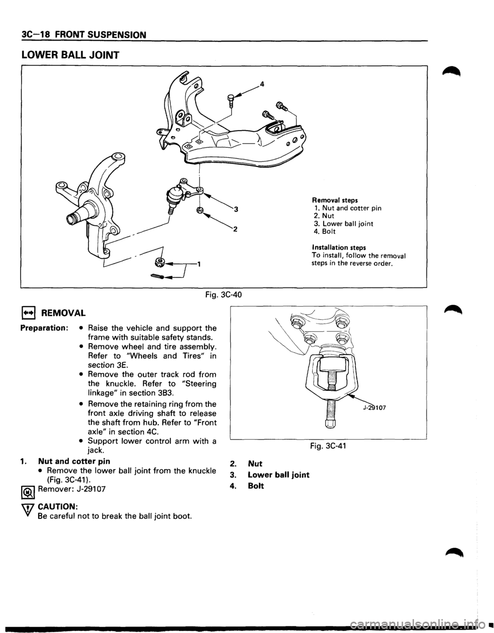
LOWER BALL JOINT
Fig. 3C-40
1••1 REMOVAL
Preparation: • Raise the vehicle and support the
frame
with suitable safety stands.
• Remove wheel and tire assembly.
Refer to "Wheels and Tires" in
section
3E.
• Remove the outer track rod from
the knuckle. Refer to "Steering
linkage"
in section 383.
• Remove the retaining ring from the
front axle driving shaft to release
the shaft from hub. Refer to "Front
axle"
in section 4C.
• Support lower control arm with a
jack.
1. Nut and cotter pin
• Remove the lower ball joint from the knuckle
(Fig. 3C-41).
1®..1 Remover: J-291 07
\f7 CAUTION:
VI Be careful not to break the ball joint boot.
2. Nut
3. Lower ball joint
4. Bolt
Removal steps 1. Nut and cotter pin
2. Nut
3. Lower
ball joint 4. Bolt
Installation
steps
To
install, follow the removal steps in the reverse order.
Fig. 3C-41
..
Page 197 of 1928
J-39792-1
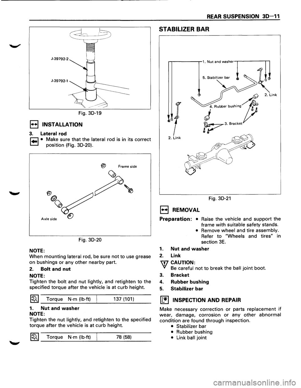
Fig. 30-19
1•+1 INSTALLATION
3. Lateral rod
~ • Make sure that the lateral rod is in its correct
~ position (Fig. 30-20).
Frame side
Axle side
Fig. 30-20
NOTE:
When mounting lateral rod, be sure not to use grease
on bushings
or any other nearby part.
2. Bolt and nut
NOTE:
Tighten the bolt and nut lightly, and retighten to the
specified torque after the
vehicle is at curb height.
~~~ Torque N·m (lb·ft)
1. Nut and washer
NOTE:
137 (101)
Tighten the nut lightly, and retighten to the specified
torque after the
vehicle is at curb height.
1~1 Torque N·m (lb·ft) 78 (58)
REAR SUSPENSION 30-11
STABILIZER BAR
2. Link
Fig. 30-21
EJ REMOVAL
Preparation: • Raise the vehicle and support the
frame
with suitable safety stands.
• Remove wheel and tire assembly.
Refer
to "Wheels and tires" in
section
3E.
1. Nut and washer
2. Link
\fl CAUTION:
VI Be careful not to break the ball joint boot.
3. Bracket
4. Rubber bushing
5. Stabilizer bar
[!] INSPECTION AND REPAIR
Make necessary correction or parts replacement if
wear, damage, corrosion or any other abnormal
condition are found through inspection.
• Stabilizer bar
• Rubber bushing
• Link ball joint
Page 201 of 1928
WHEELS AND TIRES 3E-1
SECTION 3E
WHEELS AND TIRES
W CAUTION:
When fasteners are removed, always reinstall them at the same location from which they were removed.
If a fastener needs to be replaced, use the correct part number fastener for that application. If the correct
part
number fastener is not available, a fastener of equal size and strength (or stronger) may be used.
Fasteners
that are not reused, and those requiring thread locking compound, will be called out. The correct
torque value must be used when installing fasteners that require it. If the above conditions are not
followed, parts or system damage could result.
CONTENTS
General Description . . . . . . . . . . . . . . . . . . . . . . . . . . . . . . . 3 E -1 Unit Repair .......................................... 3E-7
Diagnosis ........................................... 3E-2 Tires ............................................... 3E-7
Irregular and Premature Wear ................ 3E-2 Wheels ............................................ 3E-7
Inflation of Tires ................................. 3 E- 3 General Balance Procedure ................... 3E-8
Diagnosis List. . . . . . . . . . . . . . . . . . . . . . . . . . . . . . . . . . . . 3 E- 3 Balancing Wheel and Tire ...................... 3E-8
On-Vehicle Service ................................ 3E-6 Main Data and Specifications .................... 3E-9
Wheels ............................................ 3E-6 General Specifications ......................... 3E-9
Torque Specifications .......................... 3E-9
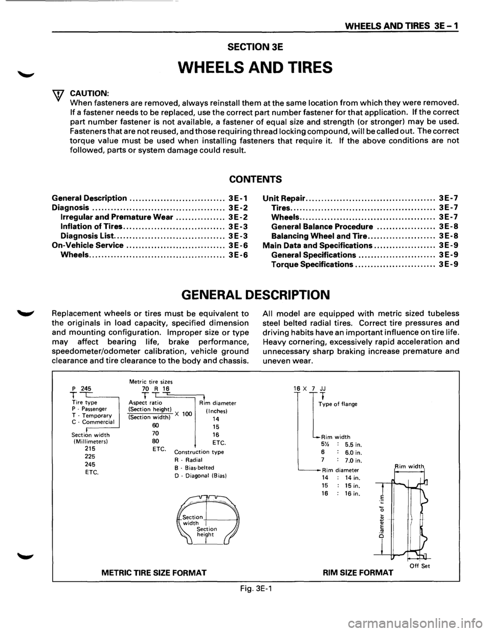
GENERAL DESCRIPTION
Replacement wheels or tires must be equivalent to
the originals in load capacity, specified dimension
and mounting configuration. Improper size or type
may affect bearing life, brake performance,
speedometer/odometer calibration, vehicle ground
clearance and tire clearance to the body and chassis.
p 245
T Tire type P -Passenger T -Temporary C -Commercial
Section
width (Millimeters) 215 225
245
ETC.
Metric tire sizes 70 R 16 T ,...
Aspect ratio I Rim diameter
(Section height)
(Section
width) X 100 (Inches)
14 60 70
80 ETC.
15
16 ETC.
Construction type
R-Radial
B - Bias-belted
D - Diagonal (Bias)
METRIC TIRE SIZE FORMAT
All model are equipped with metric sized tubeless
steel belted radial
tires. Correct tire pressures and
driving habits have an important influence on tire life.
Heavy cornering, excessively rapid acceleration and
unnecessary sharp braking increase
premature and
uneven wear.
16 X 7 JJ
I
~pe of flange
Rim width 5% 5.5 in.
6 6.0 in. 7 7.0 in.
Rim diameter Rim width
14 14 in. 15 15 in. 16 : 16 in.
I Off Set RIM SIZE FORMAT
Fig. 3E-1
Page 202 of 1928
3E-2 WHEELS AND TIRES
DIAGNOSIS
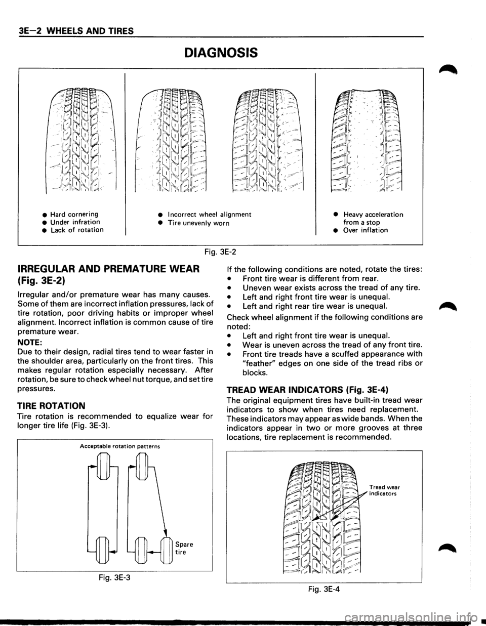
• Hard cornering • Incorrect wheel alignment
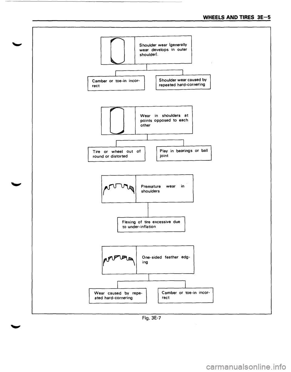
• Heavy acceleration from a stop • Under infration • Tire unevenly worn • Lack of rotation • Over inflation
Fig. 3E-2
IRREGULAR AND PREMATURE WEAR
(Fig. 3E-2)
Irregular and/or premature wear has many causes.
Some of them are incorrect inflation pressures, lack of
tire rotation, poor driving habits or improper wheel
alignment. Incorrect inflation
is common cause of tire
premature wear.
NOTE:
Due to their design, radial tires tend to wear faster in
the
shoulder area, particularly on the front tires. This
makes
regular rotation especially necessary. After
rotation, be sure to check wheel nut torque, and set tire
pressures.
TIRE ROTATION
Tire rotation is recommended to equalize wear for
longer tire life (Fig. 3E-3).
Acceptable rotation patterns
Fig. 3E-3
Spare tire
If the following conditions are noted, rotate the tires:
• Front tire wear is different from rear.
• Uneven wear exists across the tread of any tire.
• Left and right front tire wear is unequal.
•
Left and right rear tire wear is unequal.
Check wheel alignment if the following conditions are
noted:
• Left and right front tire wear is unequal.
•
Wear is uneven across the tread of any front tire.
• Front tire treads have a scuffed appearance with
"feather" edges on one side of the tread ribs or
blocks.
TREAD WEAR INDICATORS (fig. 3E-4)
The original equipment tires have built-in tread wear
indicators to show when tires need replacement.
These indicators may appear as wide bands. When the
indicators appear in
two or more grooves at three
locations, tire replacement is recommended.
Fig. 3E-4
Tread wear
indicators
•
Page 203 of 1928
INFLATION OF TIRES
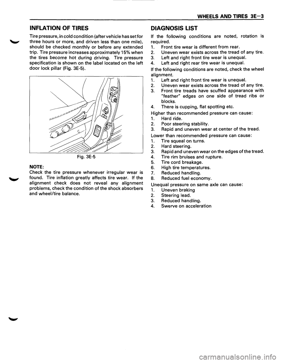
Tire pressure, in cold condition (after vehicle has setfor
three hours or more, and driven less than one mile),
should
be checked monthly or before any extended
trip. Tire pressure increases
approximately 15% when
the tires become hot during driving. Tire pressure
specification is shown on the
label located on the left
door lock pillar (Fig. 3E-5).
Fig.
3E-5
NOTE:
Check the tire pressure whenever irregular wear is
found. Tire
inflation greatly affects tire wear. If the
alignment check does not reveal any alignment
problems,
check the condition of the shock absorbers
and
wheel/tire balance.
WHEELS AND TIRES 3E-3
DIAGNOSIS LIST
If the following conditions are noted, rotation is
required.
1. Front tire wear is different from rear.
2. Uneven wear exists across the tread of any tire.
3. Left and right front tire wear is unequal.
4. Left and right rear tire wear is unequal.
If
the following conditions are noted, check the wheel
alignment.
1. Left and right front tire wear is unequal.
2. Uneven wear exists across the tread of any tire.
3. Front tire treads have scuffed appearance with
"feather" edges on one side of tread ribs or
blocks.
4. There is cupping, flat spotting etc.
Higher than recommended pressure can cause:
1. Hard ride.
2. Poor steering stability.
3. Rapid and uneven wear at center of the tread.
Lower than recommended pressure can cause:
1. Tire squeal on turns.
2. Hard steering.
3. Rapid and uneven wear on the edges of the tread.
4. Tire rim bruises and rupture.
5. Tire cord breakage.
6. High tire temperatures.
7. Reduced handling.
8. Reduced fuel economy.
Unequal pressure on same axle can cause:
1. Uneven braking
2. Steering lead.
3. Reduced handling.
4. Swerve on acceleration
Page 204 of 1928
3E-4 WHEELS AND TIRES
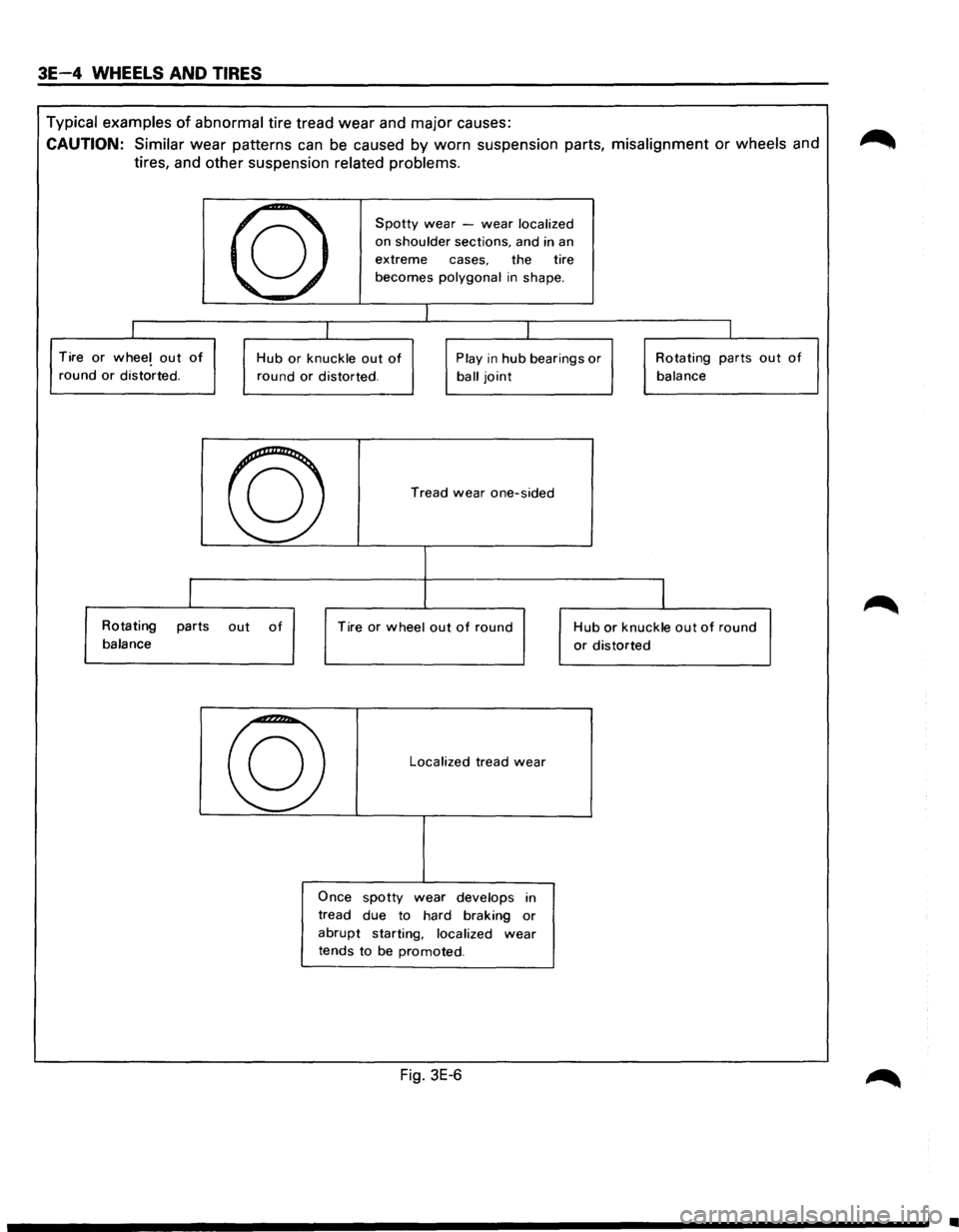
Typical examples of abnormal tire tread wear and major causes:
CAUTION: Similar wear patterns can be caused by worn suspension parts, misalignment or wheels and
tires, and other suspension
related problems.
I
Tire or wheel out of
round or distorted.
I
Rotating parts
balance
-
10
Spotty wear -wear localized
, on shoulder sections, and in an
extreme cases. the tire
'
becomes polygonal in shape.
I
I I
I
Hub or knuckle out of Play in hub bearings or Rotating parts
round or distorted.
ball joint
-
ro
out of
Tread wear one-sided
Tire or wheel out of round
Localized tread wear
Once spotty wear develops in
tread due to hard braking
or
abrupt starting, localized wear
tends to be promoted.
Fig. 3E-6
balance
I
Hub or knuckle out of round
or distorted
out of
•
Page 205 of 1928
WHEELS AND TIRES 3E-5
0
Shoulder wear (generally
wear develops in outer
shoulder).
I
I I
Camber or toe-in incor- Shoulder
wear caused by
rect repeated hard-cornering
,. .........
Wear in shoulders at
points
opposed to each
other
......
""""" I
I I
Tire or wheel out of Play in bearings or ball
round or distorted joint
~
Premature wear
in
shoulders
Flexing
of tire excessive due
to under-inflation
~
One-sided feather edg-
ing
I
l -I
Wear caused
by
repe- Camber or toe-in incor-
ated hard-cornering
rect
Fig. 3E-7
Page 206 of 1928
3E 6 WHEELS AND TIRES
ON-VEHICLE SERVICE
WHEELS
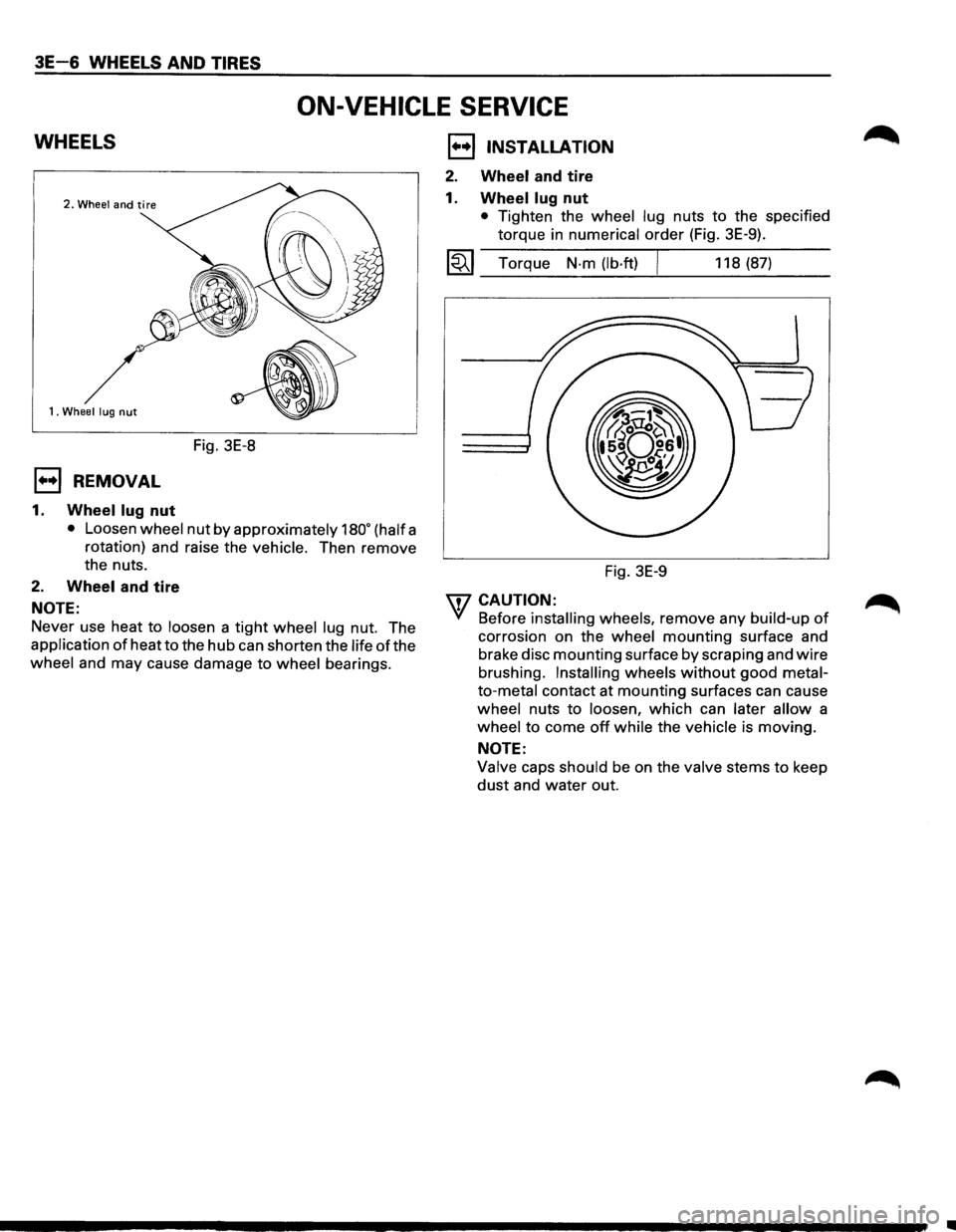
1. Wheel lug nut
Fig. 3E-8
E) REMOVAL
1. Wheel lug nut
• Loosen wheel nut by approximately 180• (half a
rotation) and raise the
vehicle. Then remove
the nuts.
2. Wheel and tire
NOTE:
Never use heat to loosen a tight wheel lug nut. The
application
of heat to the hub can shorten the life of the
wheel and may cause damage to wheel bearings.
1••1 INSTALLATION
2. Wheel and tire
1.
Wheel lug nut
• Tighten the wheel lug nuts to the specified
torque in numerical
order (Fig. 3E-9).
l~l Torque N-m (lb·ft) I 118 (87)
Fig. 3E-9
\fl CAUTION: .
'({ Before installing wheels, remove any build-up of
corrosion on the wheel mounting surface and
brake disc
mounting surface by scraping and wire
brushing. Installing wheels without good metal
to-metal contact at mounting surfaces can cause
wheel nuts to loosen, which can later allow a
wheel to come off while the vehicle is moving.
NOTE:
Valve caps should be on the valve stems to keep
dust and water out.
•