tires ISUZU TROOPER 1995 User Guide
[x] Cancel search | Manufacturer: ISUZU, Model Year: 1995, Model line: TROOPER, Model: ISUZU TROOPER 1995Pages: 1928
Page 129 of 1928
DIAGNOSIS 3-9
TIRE DIAGNOSIS
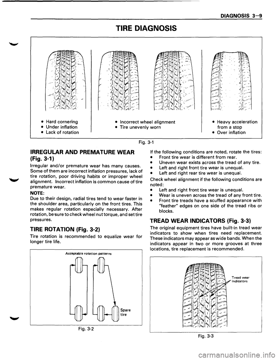
• Hard cornering • Incorrect wheel alignment • Heavy acceleration
from a
stop • Under inflation
• Tire unevenly worn
• Lack of rotation • Over inflation
Fig. 3-1
IRREGULAR AND PREMATURE WEAR
(Fig. 3-1)
Irregular and/or premature wear has many causes.
Some of them are incorrect inflation pressures, lack of
tire rotation, poor driving habits or improper wheel
alignment. Incorrect inflation
is common cause of tire
premature wear.
NOTE:
Due to their design, radial tires tend to wear faster in
the
shoulder area, particularly on the front tires. This
makes
regular rotation especially necessary. After
rotation,
be 'Sure to check wheel nut torque, and set tire
pressures.
TIRE ROTATION (Fig. 3-2)
Tire rotation is recommended to equalize wear for
longer tire life.
Acceptable rotation patterns
Fig. 3-2
Spare tire
If the following conditions are noted, rotate the tires:
• Front tire wear is different from rear.
• Uneven wear exists across the tread of any tire.
• Left and right front tire wear is unequal.
•
Left and right rear tire wear is unequal.
Check wheel alignment if the following conditions are
noted:
• Left and right front tire wear is unequal.
•
Wear is uneven across the tread of any front tire.
• Front tire treads have a scuffed appearance with
"feather" edges on one side of the tread ribs or
blocks.
TREAD WEAR INDICATORS (Fig. 3-3)
The original equipment tires have built-in tread wear
indicators to show when tires need replacement.
These indicators may appear as wide bands. When the
indicators appear in
two or more grooves at three
locations, tire replacement is recommended.
Fig. 3-3
Tread wear
indicators
Page 130 of 1928
3-10 DIAGNOSIS
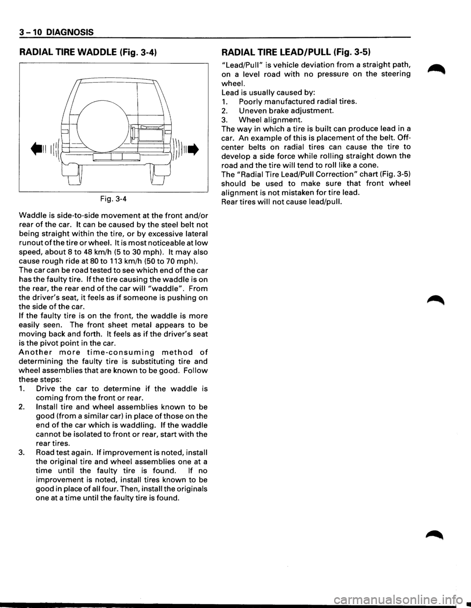
RADIAL TIRE WADDLE (Fig. 3-4)
Fig. 3-4
Waddle is side-to-side
movement at the front and/or
rear of the car. It can be caused by the steel belt not
being straight within the tire, or by excessive lateral
runout of the tire or wheel. It is most noticeable at low
speed, about 8 to 48 km/h (5 to 30 mph). It may also
cause
rough ride at 80 to 113 km/h (50 to 70 mph).
The car can be road tested
to see which end of the car
has
the faulty tire. If the tire causing the waddle is on
the rear, the rear end
of the car will "waddle". From
the
driver's seat, it feels as if someone is pushing on
the side
of the car.
If the faulty tire is on the front, the waddle is more
easily seen. The front sheet metal appears to be
moving back and forth. It feels as if the driver's seat
is
the pivot point in the car.
Another more time-consuming method of
determining the faulty tire is substituting tire and
wheel assemblies
that are known to be good. Follow
these steps:
1. Drive the car to determine if the waddle is
coming from the front or rear.
2. Install tire and wheel assemblies known to be
good (from a similar car) in place ofthose on the
end
of the car which is waddling. If the waddle
cannot be isolated to front or rear, start with the
rear tires.
3. Road test again. If improvement is noted, install
the original tire and wheel assemblies one at a
time until the faulty tire is found. If no
improvement is noted, install tires known to be
good in place of all four. Then, install the originals
one at a
time until the faulty tire is found.
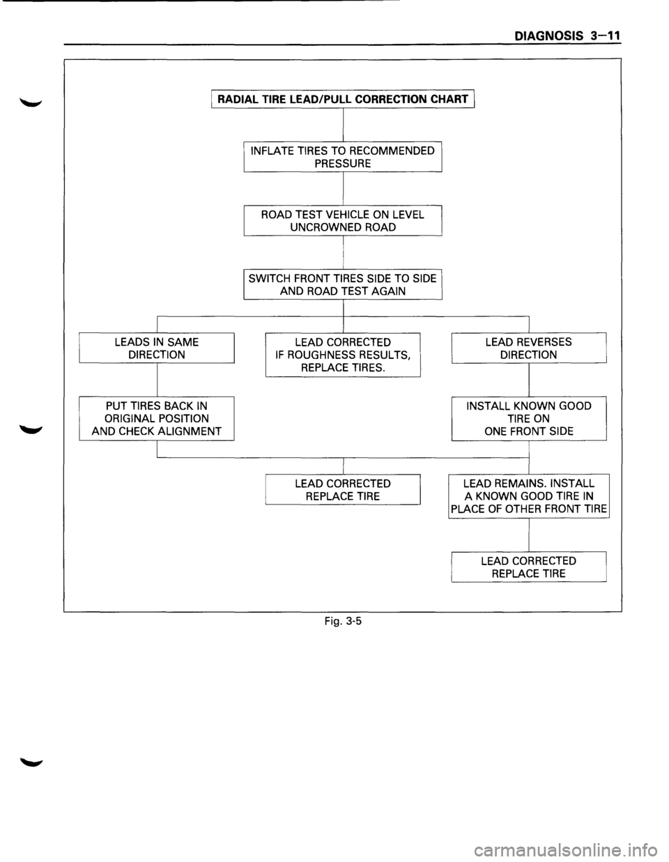
RADIAL TIRE LEAD/PULL (Fig. 3-5)
"Lead/Pull" is vehicle deviation from a straight path,
on a level road
with no pressure on the steering
wheel.
Lead is usually caused by:
1. Poorly manufactured radial tires.
2. Uneven brake adjustment.
3. Wheel alignment.
The
way in which a tire is built can produce lead in a
car.
An example of this is placement of the belt. Off
center belts on radial tires can cause the tire to
develop a side force while rolling straight down the
road and the tire will tend to roll like a cone.
The
"Radial Tire Lead/Pull Correction" chart (Fig. 3-5)
should be used to make sure that front wheel
alignment is not mistaken for tire lead.
Rear
tires will not cause lead/pull.
II
Page 131 of 1928
DIAGNOSIS 3-11
I RADIAL TIRE LEAD/PULL CORRECTION CHART I
I INFLATE TIRES TO RECOMMENDED I
PRESSURE
I
ROAD TEST VEHICLE ON LEVEL
I UNCROWNED ROAD
I SWITCH FRONT TIRES SIDE TO SIDE I
AND ROAD TEST AGAIN
LEADS IN
SAME LEAD CORRECTED LEAD REVERSES
DIRECTION
IF ROUGHNESS RESULTS, DIRECTION
REPLACE TIRES.
PUT TIRES
BACK IN INSTALL KNOWN GOOD
ORIGINAL POSITION
TIRE ON
AND CHECK ALIGNMENT ONE FRONT SIDE
LEAD CORRECTED LEAD REMAINS. INSTALL
REPLACE TIRE
A KNOWN GOOD TIRE IN
PLACE OF OTHER FRONT TIRE
LEAD CORRECTED
REPLACE TIRE
Fig. 3-5
Page 134 of 1928
3A-2 FRONT END ALIGNMENT
DEFINITION OF TERMS
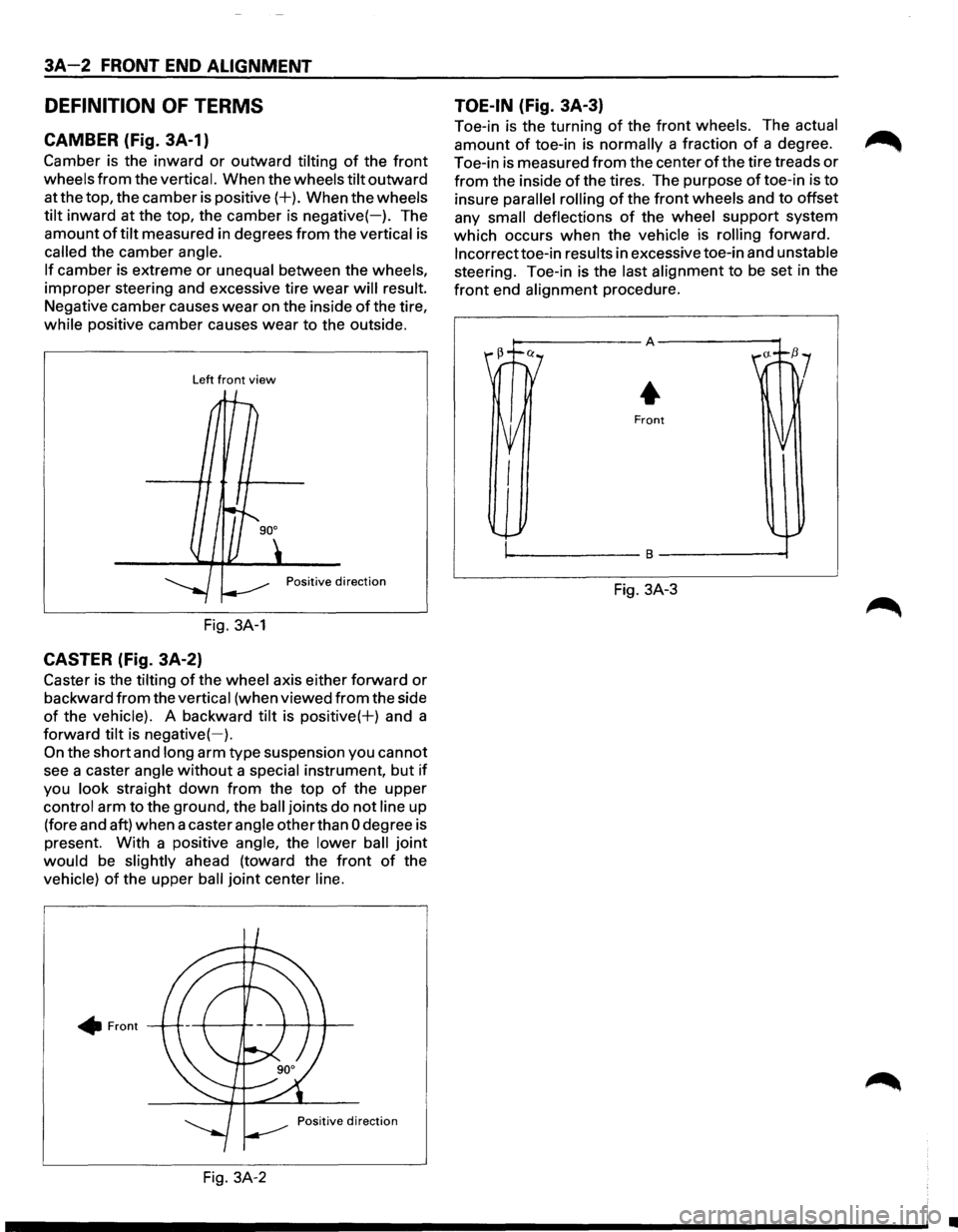
CAMBER (Fig. 3A-1)
Camber is the inward or outward tilting of the front
wheels from the vertical. When the wheels tilt outward
at the top, the camber is
positive(+). When the wheels
tilt inward at the top, the camber is negative(-). The
amount
of tilt measured in degrees from the vertical is
called the camber angle.
If camber is extreme or unequal between the wheels,
improper steering and excessive tire
wear will result.
Negative camber causes
wear on the inside of the tire,
while positive camber causes wear to the outside.
Left front view
Positive direction
Fig. 3A-1
CASTER (Fig. 3A-2)
Caster is the tilting of the wheel axis either forward or
backward from the vertical (when viewed from the side
of the vehicle). A backward tilt is positive(+) and a
forward tilt is
negative(-).
On the short and long arm type suspension you cannot
see a caster angle
without a special instrument, but if
you look straight down from the top of the upper
control arm to the ground, the
ball joints do not line up
(fore and aft) when a caster angle other than
0 degree is
present. With a positive angle, the lower
ball joint
would be slightly ahead (toward the front of the
vehicle)
of the upper ball joint center line .
• Front
Fig. 3A-2
TOE-IN (Fig. 3A-3)
Toe-in is the turning of the front wheels. The actual
amount of toe-in is normally a fraction of a degree.
Toe-in is measured
from the center of the tire treads or
from the inside of the tires. The purpose of toe-in is to
insure
parallel rolling of the front wheels and to offset
any
small deflections of the wheel support system
which occurs
when the vehicle is rolling forward.
lncorrecttoe-in results in excessive toe-in and unstable
steering. Toe-in is the last alignment to
be set in the
front end alignment procedure.
Fig. 3A-3
•
Page 135 of 1928
FRONT END ALIGNMENT 3A-3
ON-VEHICLE SERVICE
INSPECTION
Before making any adjustments affecting caster,
camber or toe-in, the following front end inspection
should be made.
I L•IINSPECT
1. Tires for proper inflation pressure. Refer to
"Wheels and Tires" in section 3E.
2. Front wheel bearings for proper adjustment.
Refer to "Front Wheel Drive" in section 4C.
3. Ball joints, tie rod ends and relay rods. If
excessive looseness is noted, correct before
adjusting. Refer
to "Steering Linkage" in section
3B3.
4. Wheel and tires for run-out. Refer to "Wheels
and Tires" in section 3E.
5. Trim height. If not within specifications, the
correction
must be made before adjusting caster.
6. Steering gear for looseness at the frame.
7. Shock absorbers for leaks or any noticeable
noise.
Refer
to "Front Suspension" in section 3C.
8. Control arms or stabilizer bar attachment for
looseness. Refer to "Front Suspension" in section
3C.
9. Alignment equipment. Follow the manufacturer's
instructions.
10. Level of the vehicle. The vehicle must be on a
level surface.
TRIM HEIGHT ADJUSTMENT
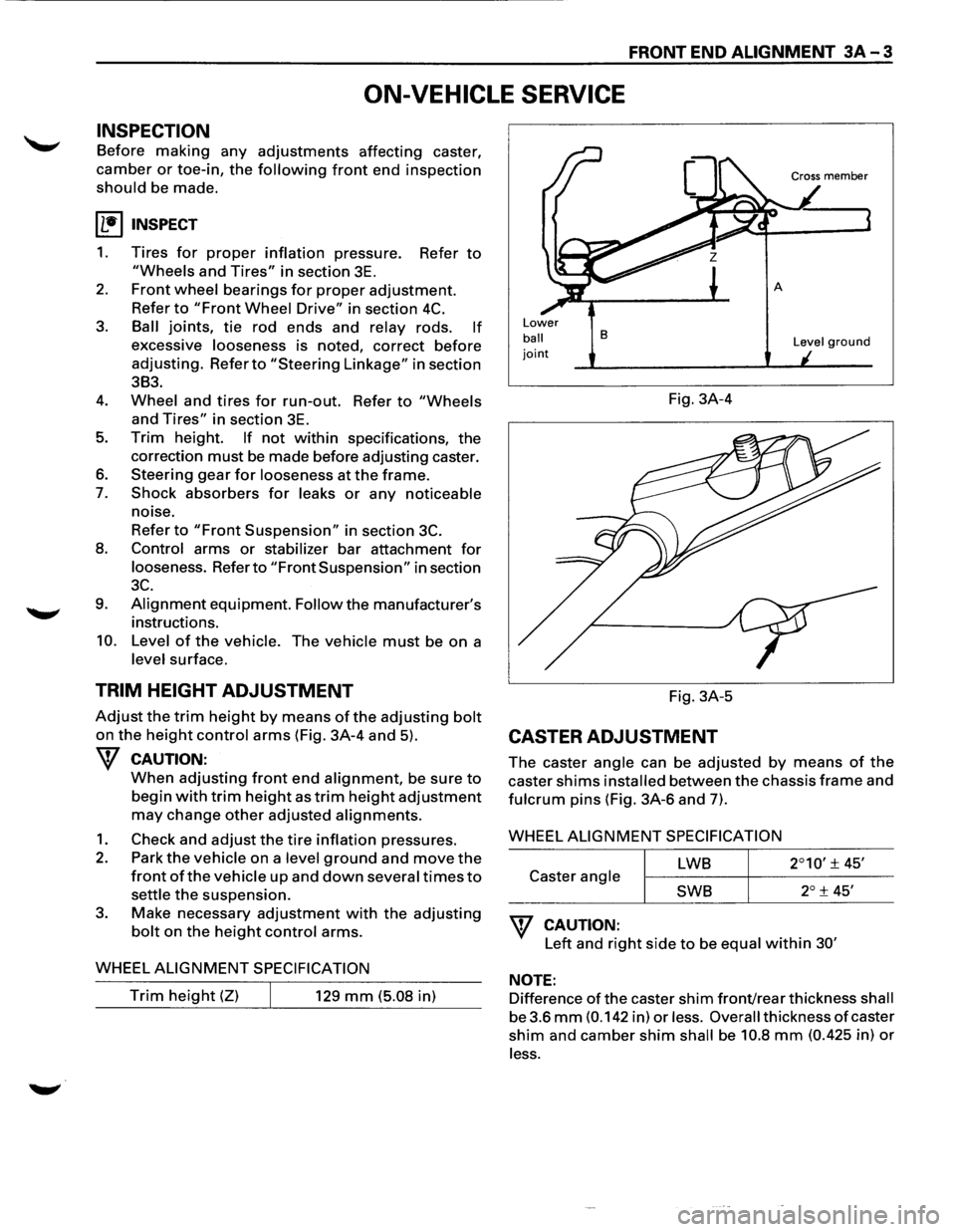
Adjust the trim height by means of the adjusting bolt
on the height control arms (Fig. 3A-4 and 5).
W CAUTION:
When adjusting front end alignment, be sure to
begin with trim height as trim height adjustment
may change other adjusted alignments.
1. Check and adjust the tire inflation pressures.
2. Park the vehicle on a level ground and move the
front of the vehicle up and down several times to
settle the suspension.
3. Make necessary adjustment with the adjusting
bolt on the height control arms.
WHEEL
ALIGNMENT SPECIFICATION
Trim height (Z) 129 mm (5.08 in)
Lower
ball joint
B
Fig. 3A-4
Fig. 3A-5
CASTER ADJUSTMENT
Level ground
The caster angle can be adjusted by means of the
caster shims installed between the chassis frame and
fulcrum pins (Fig. 3A-6 and 7).
WHEEL
ALIGNMENT SPECIFICATION
LWB
Caster angle
SWB
W CAUTION:
Left and right side to be equal within 30'
NOTE:
Difference of the caster shim front/rear thickness shall
be 3.6
mm (0.142 in) or less. Overall thickness of caster
shim and camber shim shall be 10.8 mm (0.425 in) or
less.
Page 143 of 1928
STEERING WHEEL FREE PLAY ADJUST
MENT
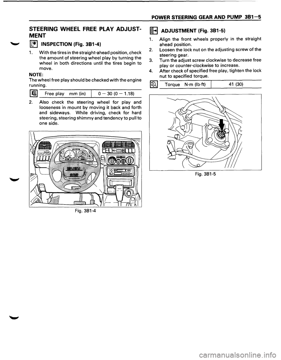
IL•I INSPECTION (Fig. 381-4)
1. With the tires in the straight-ahead position, check
the
amount of steering wheel play by turning the
wheel in both directions until the tires begin to
move.
NOTE:
The wheel free play should be checked with the engine
running.
~~~~F-r-ee--pl-ay---m-m--(in_)_,j--o----3-0-(0----1-.1-8~)-
2. Also check the steering wheel for play and
looseness in mount by moving it back and forth
and sideways.
While driving, check for hard
steering, steering
shimmy and tendency to pull to
one side.
POWER STEERING GEAR AND PUMP 381-5
IEEI ADJUSTMENT (Fig. 381-5)
1. Align the front wheels properly in the straight
ahead position.
2. Loosen the lock nut on the adjusting screw of the
steering gear.
3. Turn the adjust screw clockwise to decrease free
play or counter-clockwise to incre~se.
4. After check of specified free play, t1ghten the lock
nut to specified torque.
~~~ Torque N·m (lb·ft) I 41 (30)
Fig. 381-5
Page 160 of 1928
383 - 4 STEERING LINKAGE
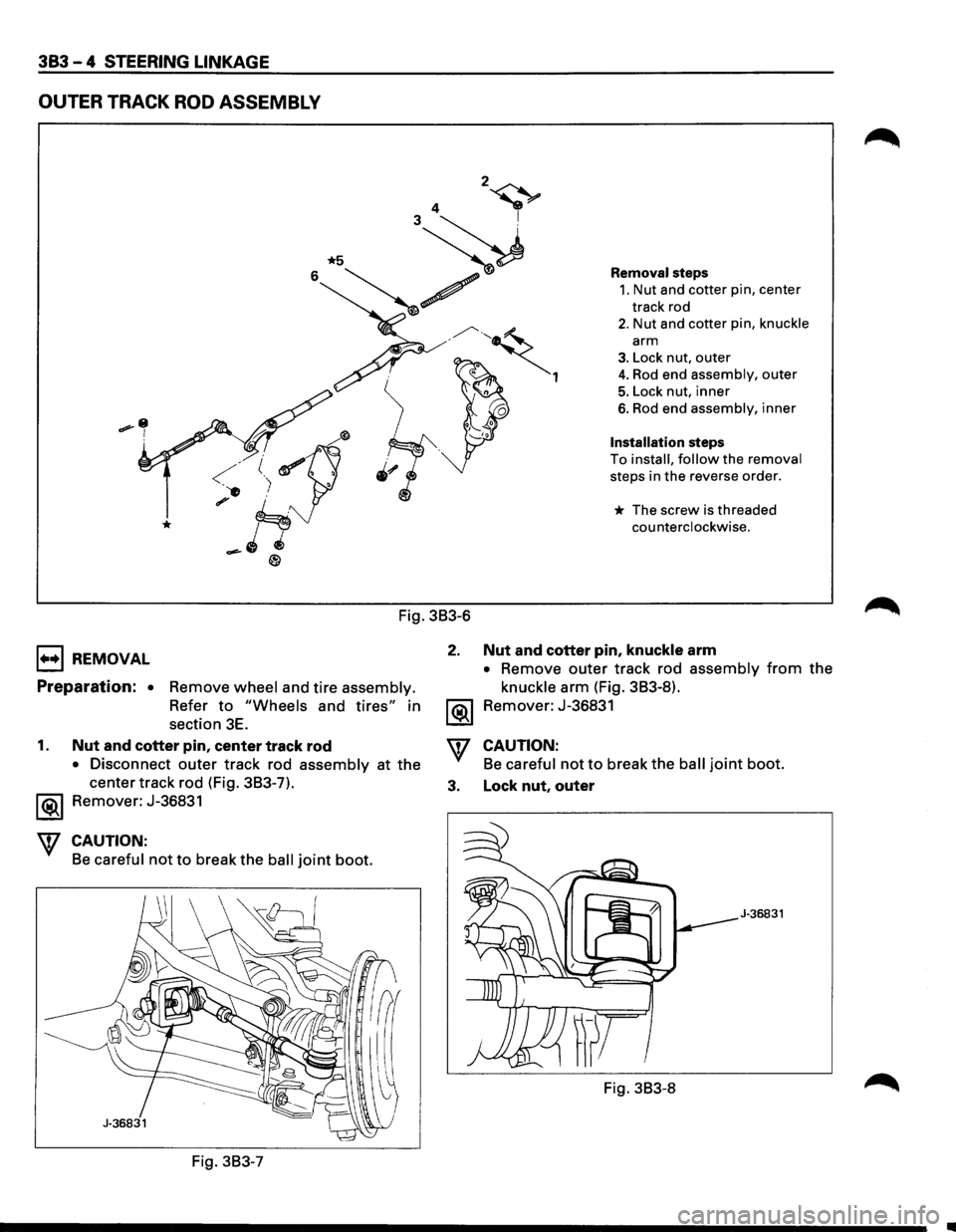
OUTER TRACK ROD ASSEMBLY
1+•1 REMOVAL
Fig. 3B3-6
2.
Preparation: • Remove wheel and tire assembly.
Refer to "Wheels and tires" in
section
3E. ~
Removal steps
1. Nut and cotter pin, center
track rod
2. Nut and cotter pin, knuckle
arm
3. Lock nut, outer
4. Rod end assembly, outer
5. Lock nut, inner
6. Rod end assembly, inner
Installation steps
To install, follow the removal
steps in the reverse order.
* The screw is threaded
counterclockwise.
Nut and cotter pin, knuckle arm
• Remove outer track rod assembly from the
knuckle arm (Fig. 3B3-8).
Remover: J-36831
1. Nut and cotter pin, center track rod
• Disconnect outer track rod assembly at the
center track rod (Fig. 3B3-7).
'\f CAUTION:
Be careful not to break the ball joint boot.
3. Lock nut, outer Remover: J-36831
CAUTION:
Be careful not to break the ball joint boot.
J-36831
Fig. 3B3-8
Fig. 3B3-7
Page 167 of 1928
FRONT SUSPENSION 3C-3
ON-VEHICLE SERVICE
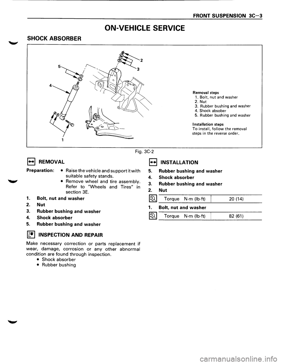
SHOCK ABSORBER
Fig. 3C-2
1••1 REMOVAL
Preparation: • Raise the vehicle and support it with
suitable safety stands.
'W' • Remove wheel and tire assembly.
Refer to "Wheels and Tires" in
section
3E.
1. Bolt, nut and washer
2. Nut
3. Rubber bushing and washer
4. Shock absorber
5. Rubber bushing and washer
IL'it'l INSPECTION AND REPAIR
Make necessary correction or parts replacement if
wear, damage, corrosion or any other abnormal
condition are found through inspection.
• Shock absorber
• Rubber bushing
EJ
5.
4.
3.
2.
~
1.
~
Removal steps
1.
Bolt, nut and washer 2. Nut
3. Rubber bushing and washer
4.
Shock absober 5. Rubber bushing and washer
Installation steps To install, follow the removal steps in the reverse order.
INSTALLATION
Rubber bushing and washer
Shock absorber
Rubber bushing and washer
Nut
Torque N-m (lb·ft) 20 (14)
Bolt, nut and washer
Torque N-m (lb·ft) 82 (61)
Page 168 of 1928
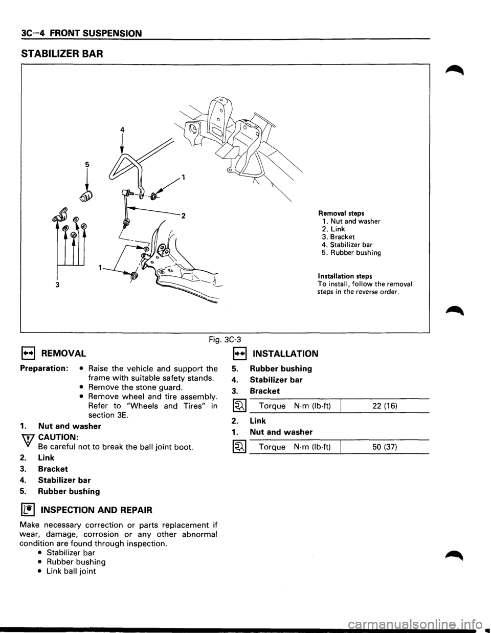
3C-4 FRONT SUSPENSION
STABILIZER BAR
5
l
3
Removal steps
1. Nut and washer
2. Link 3. Bracket
4. Stabilizer bar 5. Rubber bushing
Installation steps To install, follow the removal steps in the reverse order.
Fig. 3C-3
1••1 REMOVAL
Preparation: • Raise the vehicle and support the
frame
with suitable safety stands.
• Remove the stone guard.
• Remove wheel and tire assembly.
Refer to "Wheels and Tires" in
section
3E.
1. Nut and washer
W CAUTION:
VI Be careful not to break the ball joint boot.
2. Link
3. Bracket
4. Stabilizer bar
5. Rubber bushing
~ INSPECTION AND REPAIR
Make necessary correction or parts replacement if
wear, damage, corrosion or any other abnormal
condition are found through inspection.
• Stabilizer bar
• Rubber bushing
• Link ball joint
1••1 INSTALLATION
5. Rubber bushing
4. Stabilizer bar
3. Bracket
~ Torque N·m (lb·ft) 22 (16)
2. Link
1. Nut and washer
~ Torque N-m (lb·ft) 50 (37)
..
Page 171 of 1928
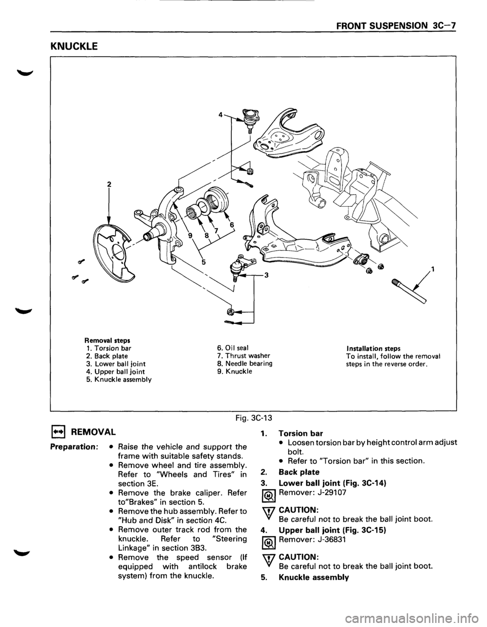
FRONT SUSPENSION 3C-7
KNUCKLE
2
~,
Removal steps 1. Torsion bar 6. Oil seal Installation steps 2.
Back plate 7. Thrust washer To install, follow the removal steps in the reverse order. 3. Lower ball joint 8. Needle bearing
4. Upper
ball joint 9. Knuckle
5. Knuckle assembly
Fig. 3C-13
1••1 REMOVAL
Preparation: • Raise the vehicle and support the
frame
with suitable safety stands.
• Remove wheel and tire assembly.
Refer to
"Wheels and Tires" in
section
3E.
• Remove the brake caliper. Refer
to"Brakes" in section 5.
• Remove the hub assembly. Refer to
"Hub and Disk" in section 4C.
• Remove outer track rod from the
knuckle. Refer to
"Steering
Linkage" in section 3B3.
• Remove the speed sensor (If
equipped with antilock brake
system)
from the knuckle. 1.
Torsion bar
• Loosen
torsion bar by height control arm adjust
bolt.
• Refer to "Torsion bar" in this section.
2. Back plate
3. Lower ball joint (Fig. 3C-14)
1®.1 Remover: J-291 07
'\f7 CAUTION:
'(! Be careful not to break the ball joint boot.
4. Upper ball joint (Fig. 3C-15)
1®.1 Remover: J-36831
'\f7 CAUTION:
'(! Be careful not to break the ball joint boot.
5. Knuckle assembly