fuel ISUZU TROOPER 1995 Repair Manual
[x] Cancel search | Manufacturer: ISUZU, Model Year: 1995, Model line: TROOPER, Model: ISUZU TROOPER 1995Pages: 1928
Page 643 of 1928
ENGINE FUEL 6C-1
SECTION 6C
ENGINE FUEL
CONTENTS
General Description ....................... .
Fuel Metering ............................ .
On-Vehicle Service ........................ .
Fuel Filter ................................. .
In Tank Fuel Filter ............................. .
Fuel Pump Flow Test ........................ .
Fuel Pump Assembly ........................ .
Fuel Pump Relay .............................. ..
6C-1
6C-2
6C-3
6C-3
6C-4
6C-4
6C-5
6C-5
Fuel Tank .......................................... ..
Fuel Gage Unit ................................. ..
Fuel Filler Cap .................................... .
Accelerator Pedal Control ............... ..
Accelerator Pedal Control Cable ..
Accelerator Pedal ......................... .
Air
Cleaner Filter ........................... .
Main Data and Specifications ............... .
Torque Specifications ......................
..
6C-6
6C-7
6C-7
6C-8
6C-8
6C-9
6C-10
6C-11
6C-11
GENERAL DESCRIPTION
When working on the fuel system, there are several
things to keep in mind:
• Any time the fuel system is being worked on,
disconnect the negative battery
cable except for
those tests where battery voltage is required.
• Always keep a dry chemical (Class 8) fire extin
guisher near the work area.
• Replace all pipes with the same pipe and fittings
that were removed.
• Clean and inspect "0" rings. Replace if required.
• Always relieve the line pressure before servicing
any fuel system components.
• Do not attempt repairs on the fuel system until you
have read the instructions and checked the pic
tures
relating to that repair.
• Adhere to all Notices and Cautions.
All gasoline engines are designed to use only unleaded
gasoline. Unleaded gasoline
must be used for proper
emission control system operation. Its use will also
minimize spark plug fouling and extend engine oil life.
Using leaded gasoline can damage the emission
control system and could result in loss of emission
warranty coverage.
All cars are equipped with an Evaporative Emission
Control System. The purpose of the system is to
minimize the escape offuel vapors to the atmosphere.
Information on this system will be found in Section
6E2.
Page 644 of 1928
6C - 2 ENGINE FUEL
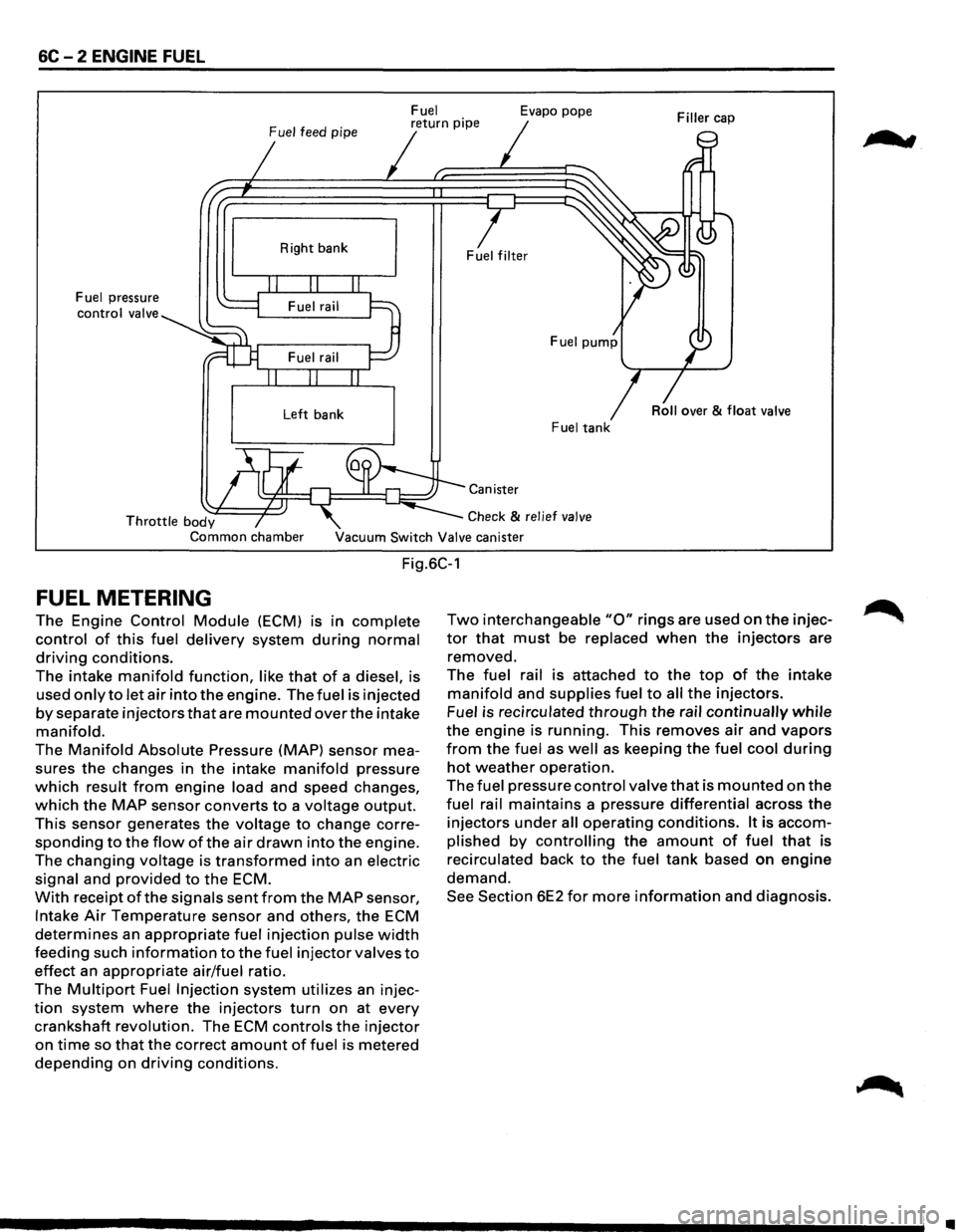
Fuel
Fuel
feed pipe return pipe Evapo pope
Fuel pressure
control valve Right
bank
Left bank Fuel tank
Canister
Throttle body Common chamber
Check & relief
valve
Vacuum Switch Valve canister
Fig.6C-1
FUEL METERING
The Engine Control Module (ECM) 1s 1n complete
control of this fuel delivery system during normal
driving conditions.
The intake manifold function, like that of a diesel, is
used
only to let air into the engine. The fuel is injected
by separate injectors that are mounted over the intake
manifold.
The Manifold Absolute Pressure (MAP) sensor mea
sures
the changes in the intake manifold pressure
which result from engine load and speed changes,
which the MAP sensor converts to a voltage output.
This sensor generates the voltage to change corre
sponding to the flow ofthe air drawn into the engine.
The
changing voltage is transformed into an electric
signal and provided to the ECM.
With receipt of the signals sent from the MAP sensor,
Intake Air Temperature sensor and others, the ECM
determines an appropriate fuel injection pulse width
feeding such information to the fuel injector valves to
effect an appropriate air/fuel ratio.
The
Multipart Fuel Injection system utilizes an injec
tion system where the injectors turn on at every
crankshaft revolution. The ECM controls the injector
on time so that the correct amount of fuel is metered
depending on driving conditions.
Two interchangeable "0" rings are used on the injec
tor that must be replaced when the injectors are
removed.
The fuel rail is attached to the top of the intake
manifold and supplies fuel to all the injectors.
Fuel is recirculated
through the rail continually while
the engine is running. This removes air and vapors
from the fuel as well as keeping the fuel cool during
hot weather operation.
The fuel pressure control valve that is mounted on the
fuel rail maintains a pressure differential across the
injectors under all operating conditions. It is accom
plished by controlling the amount of fuel that is
recirculated back
to the fuel tank based on engine
demand.
See Section 6E2 for more information and diagnosis.
;au
•
Page 645 of 1928
ENGINE FUEL 6C - 3
ON-VEHICLE SERVICE
When repair to the fuel system has been com
pleted, start engine and check the fuel system for
FUEL FILTER
2
3
loose connection or leakage. For the fuel system
diagnosis, see Section 6E.
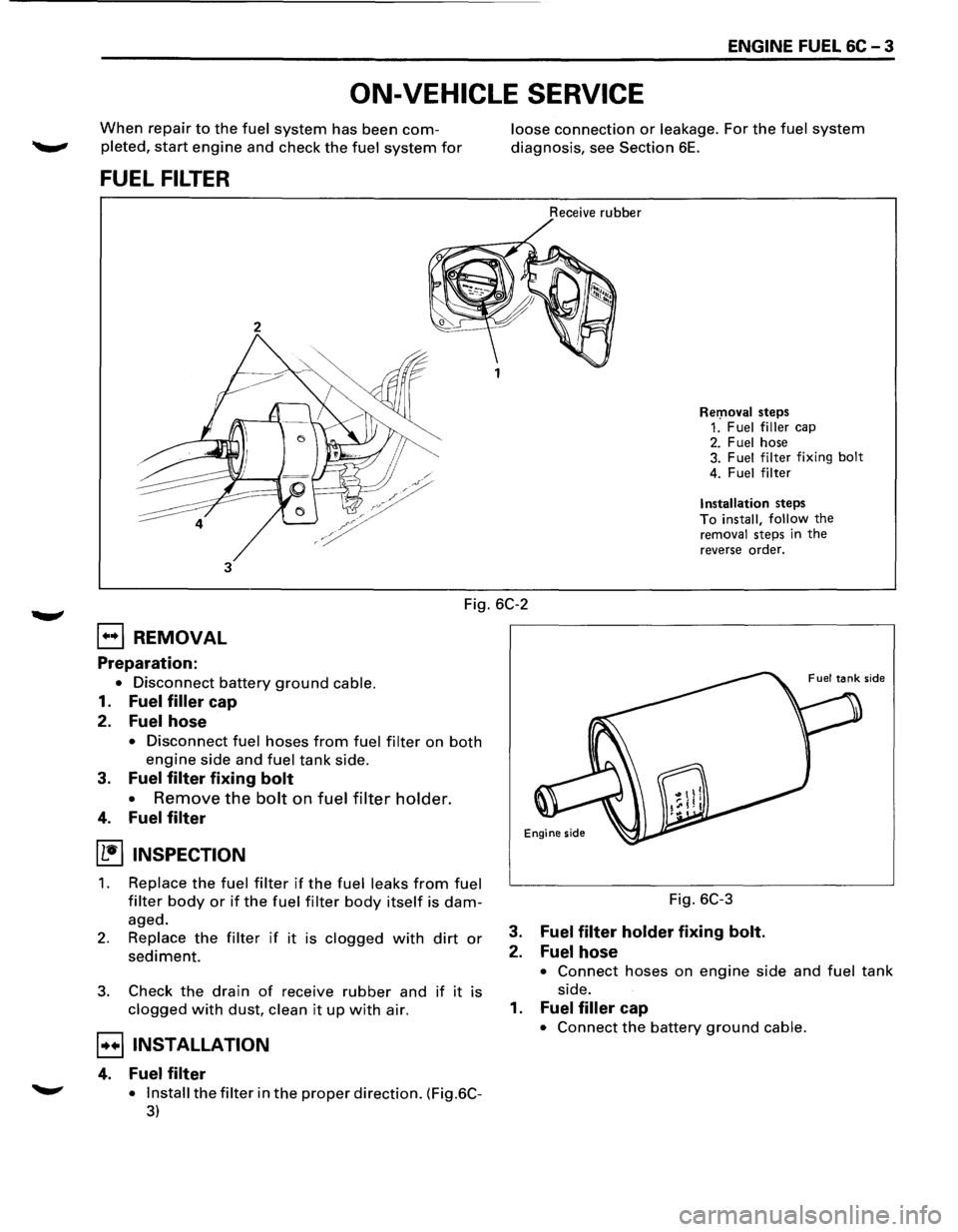
Receive rubber
Rer:noval steps 1. Fuel filler cap 2. Fuel hose
3. Fuel filter fixing bolt
4. Fuel filter
Installation steps To install, follow the removal steps in the
reverse order.
Fig. 6C-2
EJ REMOVAL
Preparation:
• Disconnect battery ground cable.
1. Fuel filler cap
2. Fuel hose
• Disconnect fuel hoses from fuel filter on both
engine side and fuel tank side.
3. Fuel filter fixing bolt
•
Remove the bolt on fuel filter holder.
4. Fuel filter
(1!] INSPECTION
1. Replace the fuel filter if the fuel leaks from fuel
filter body or if the fuel filter body itself is dam
aged.
2. Replace the filter if it is clogged with dirt or
sediment.
3. Check the drain of receive rubber and if it is
clogged with dust, clean it up with air.
B INSTALLATION
4. Fuel filter
.......,. • Install the filter in the proper direction. (Fig.6C-
3)
Fig. 6C-3
3. Fuel filter holder fixing bolt.
2. Fuel hose
• Connect hoses on engine side and fuel tank
side.
1. Fuel filler cap
• Connect the battery ground cable.
Page 646 of 1928
![ISUZU TROOPER 1995 Repair Manual 6C - 4 ENGINE FUEL
I1!]1NSPECTION
After installation, start engine and check for fuel leak
age.
IN-TANK FUEL FILTER
The filter is located on the lower end of fuel pickup
tube in the fuel tank](/img/61/57183/w960_57183-645.png "ISUZU TROOPER 1995 Repair Manual 6C - 4 ENGINE FUEL
I1!]1NSPECTION
After installation, start engine and check for fuel leak
age.
IN-TANK FUEL FILTER
The filter is located on the lower end of fuel pickup
tube in the fuel tank")
6C - 4 ENGINE FUEL
I1!]1NSPECTION
After installation, start engine and check for fuel leak
age.
IN-TANK FUEL FILTER
The filter is located on the lower end of fuel pickup
tube in the fuel tank. It prevents dirt from entering the
fuel pipe and also stops water unless the filter is
completely submerged in the water. It is a self-cleaning
type, not requiring scheduled maintenance. Excess
water and sediment in the tank restricts fuel supply to
the engine, resulting in engine stop. In such a case, the
tank
must be cleaned throughly.
FUEL PUMP FLOW TEST
If reduction of fuel supply is suspected, perform
checking as follows.
Preparation:
• Make sure that there is fuel in the tank.
• With the engine running, check the fuel feed
pipe and hose
from fuel tank to injector for
evidence of leakage.
Retighten, if pipe or hose connection is loose.
Also,
check pipes and hoses for squashing or
clogging.
1. Receive the hose from fuel feed pipe with a clean
container, and check for fuel pump flow rate.
2. Connect the pump relay terminals with a jumper
wire as shown and start the fuel pump to measure
delivery. (Fig. 6C-4)
W CAUTION:
Never generate sparks when connecting a jumper
wire.
Fig. 6C-4
Delivery Delivery
15 seconds 0.38
liters minimum
If the measure value is out of standard, conduct the
pressure test.
Pressure test
For the pressure test to the fuel system, see Section 6E
"Fuel Control System".
II
Page 647 of 1928
FUEL PUMP ASSEMBLY
1
ENGINE FUEL 6C-5
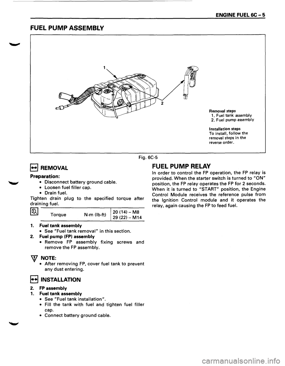
Removal steps
1. Fuel tank assembly 2. Fuel pump assembly
Installation
steps
To install, follow the removal steps in the reverse order.
Fig. 6C-5
B REMOVAL
Preparation:
• Disconnect battery ground cable.
•
Loosen fuel filler cap.
• Drain fuel.
Tighten drain plug to the specified torque after
draining fuel.
~ Torque N·m (lb.ft) 20 (14)-M8
29 (22)-M14
1. Fuel tank assembly
•
See "Fuel tank removal" in this section.
2. Fuel pump (FPI assembly
• Remove FP assembly fixing screws and
remove the FP assembly.
"'\f NOTE:
• After removing FP, cover fuel tank to prevent
any dust entering.
B INSTALLATION
2. FP assembly
1. Fuel tank assembly
• See "Fuel tank installation".
• Fill the tank with fuel and tighten fuel filler
cap.
• Connect battery ground cable.
FUEL PUMP RELAY
In order to control the FP operation, the FP relay is
provided. When the starter switch is turned to "ON"
position, the FP relay operates the FP for 2 seconds.
When it is turned to "START" position, the Engine
Control Module receives the reference pulse from
the Ignition Control module and it operates the
relay, again causing the FP to feed fuel.
Page 648 of 1928
6C-6 ENGINE FUEL
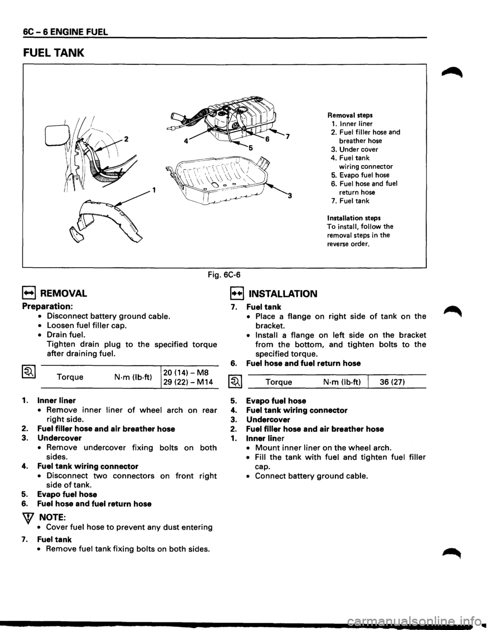
FUEL TANK
7
1 3
Removal steps
1.1nnerliner
2. Fuel filler hose and
breather hose
3. Under cover
4.
Fuel tank
wiring connector
5. Evapo fuel hose
6.
Fuel hose and fuel
return hose
7. Fuel tank
Installation steps
To
install, follow the
removal steps in the
reverse order.
Fig. 6C-6
B REMOVAL
Preparation:
• Disconnect battery ground cable.
•
Loosen fuel filler cap.
• Drain fuel.
Tighten drain plug to the specified torque
after draining fuel.
Torque
1. Inner liner
N·m (lb·ft) 20 (14)-M8
29 (22)-M14
• Remove
inner liner of wheel arch on rear
right side.
2.
Fuel filler hose and air breather hose
3.
Undercover
• Remove undercover fixing bolts on both
sides.
4. Fuel tank wiring connector
• Disconnect two connectors on front right
side of tank.
5. Evapo fuel hose
6. Fuel hose and fuel return hose
W NOTE:
• Cover fuel hose to prevent any dust entering
7. Fuel tank
• Remove fuel tank fixing bolts on both sides.
I!!] INSTALLATION
7.
6.
Fuel tank
• Place a flange on right side of tank on the
bracket.
• Install a flange on left side on the bracket
from the bottom, and tighten bolts to the
specified torque.
Fuel hose and fuel return hose
Torque N·m Ob·ft) 36 (27)
5. Evapo fuel hose
4. Fuel tank wiring connector
3. Undercover
2. Fuel filler hose and air breather hose
1. Inner liner
• Mount inner liner on the wheel arch.
• Fill the tank with fuel and tighten fuel filler
cap.
• Connect battery ground cable.
Page 649 of 1928
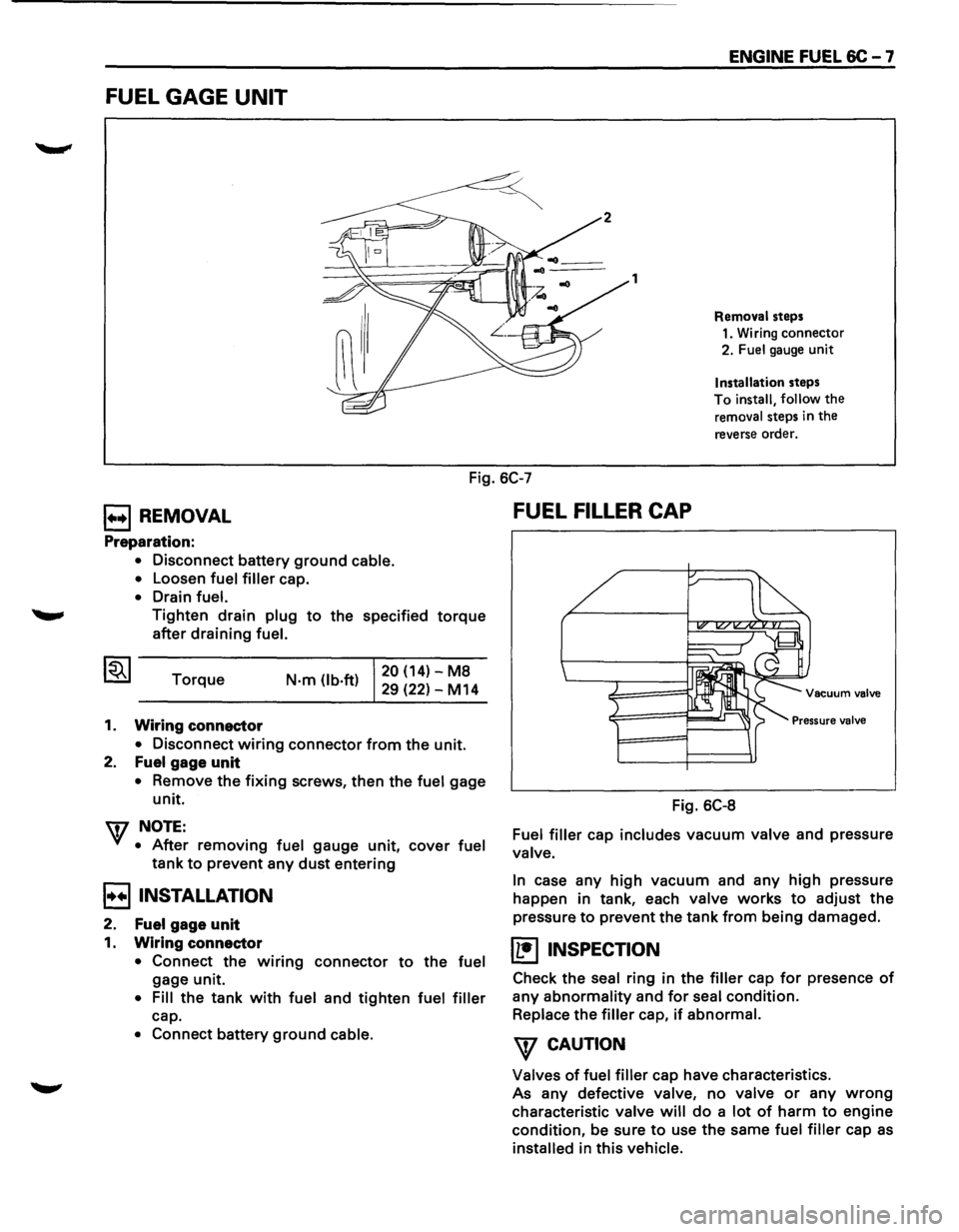
FUEL GAGE UNIT
1
ENGINE FUEL 6C - 7
Removal steps
1. Wiring connector
2. Fuel gauge unit
Installation steps
To
install, follow the
removal steps in the
reverse order.
Fig. 6C-7
E3REMOVAL ~F_U_E_L_F_IL_L_ER __ C_A_P ____________ ~
Preparation:
• Disconnect battery ground cable.
•
Loosen fuel filler cap.
• Drain fuel.
Tighten drain plug to the specified torque
after draining fuel.
Torque
1. Wiring connector
N-m (lb·ft) 20 (14)-M8
29 (22)-M14
• Disconnect wiring connector from the unit.
2. Fuel
gage unit
• Remove the fixing screws, then the fuel gage
unit.
w NOTE:
• After removing fuel gauge unit, cover fuel
tank to prevent any dust entering
B INSTALLATION
2. Fuel gage unit
1. Wiring connector
• Connect the wiring connector to the fuel
gage unit.
• Fill the tank with fuel and tighten fuel filler
cap.
• Connect battery ground cable.
Vacuum valve
Pressure valve
Fig. 6C-8
Fuel filler cap includes vacuum valve and pressure
valve.
In
case any high vacuum and any high pressure
happen in tank, each
valve works to adjust the
pressure to prevent the tank from being damaged.
(1!] INSPECTION
Check the seal ring in the filler cap for presence of
any abnormality and for seal condition.
Replace the filler cap, if abnormal.
\f CAUTION
Valves of fuel filler cap have characteristics.
As any defective valve, no valve or any wrong
characteristic valve will do a lot of harm to engine
condition, be sure to use the same fuel filler cap as
installed in this vehicle.
Page 650 of 1928
6C - 8 ENGINE FUEL
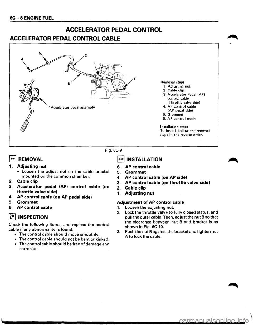
ACCELERATOR PEDAL CONTROL
ACCELERATOR PEDAL CONTROL CABLE
3
Accelerator pedal assembly Removal
steps
1. Adjusting nut 2. Cable clip
3. Accelerator Pedal (AP)
control cable
(Throttle valve side)
4. AP
control cable
(AP pedal side)
5.
Grommet
6. AP control cable
Installation steps
To install, follow the removal
steps in the reverse order.
Fig. 6C-9
EJ REMOVAL
1. Adjusting nut
• Loosen the adjust nut on the cable bracket
mounted on the common chamber.
2. Cable clip
3. Accelerator pedal (AP) control cable (on
throttle valve side)
4. AP control cable (on AP pedal side)
5. Grommet
6. AP control cable
(1!] INSPECTION
Check the following items, and replace the control
cable
if any abnormality is found.
• The control cable should move smoothly.
• The control cable should not be bent or kinked.
• The control cable should be free of damage and
corrosion.
B INSTALLATION
6. AP control cable
5. Grommet
4. AP control cable (on AP side)
3. AP control cable (on throttle valve side)
2.
Cable clip
1. Adjusting nut
Adjustment of
AP control cable
1. Loosen the adjusting nut.
2. Lock the throttle valve to fully closed status, and
pull the outer cable. Then, adjust the nut B so that
the clearance between nut B and bracket is as
shown in Fig. 6C-10.
3. Push the nut B against the bracket and tighten nut
A to lock the cable.
Page 651 of 1928
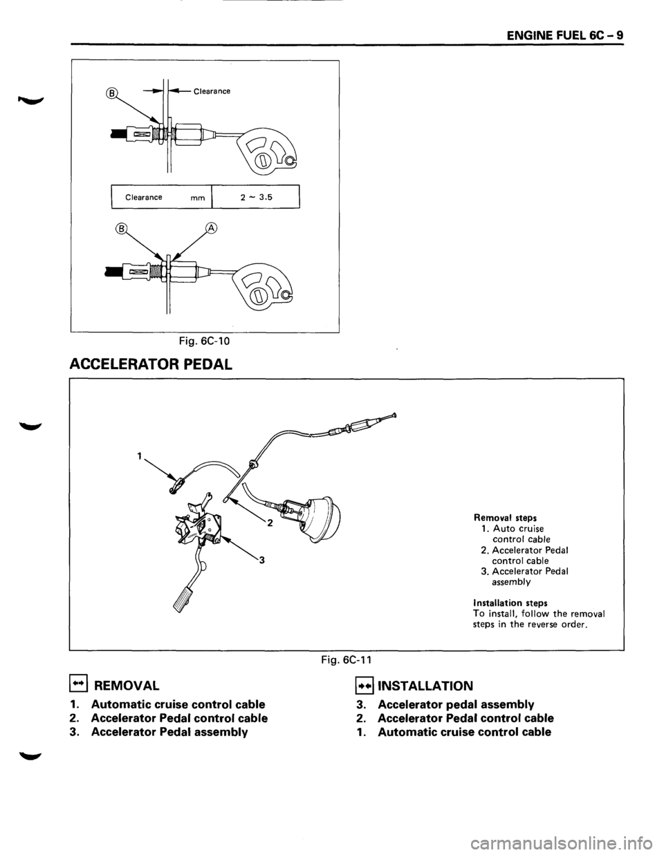
Clearance 2 -3.5
Fig. 6C-10
ACCELERATOR PEDAL
E) REMOVAL
1. Automatic cruise control cable
2. Accelerator Pedal control cable
3. Accelerator Pedal assembly
Fig. 6C-11
B INSTALLATION
ENGINE FUEL 6C - 9
Removal steps
1.
Auto cruise control cable
2. Accelerator Pedal
control cable
3. Accelerator Pedal
assembly
Installation
steps To install, follow the removal steps in the reverse order.
3. Accelerator pedal assembly
2. Accelerator Pedal control cable
1. Automatic cruise control cable
Page 652 of 1928
6C -10 ENGINE FUEL
Adjustment of pedal stroke
Manual Transmission:
• Rotate counterclockwise to loosen the stopper
bolt sufficiently.
• Fully depress the pedal and hold it there hand.
Next, rotate the stopper bolt until it hits the
stopper of pedal bracket. Then, lock the stopper
bolt there.
Automatic Transmission:
• Rotate counterclockwise to loosen the kickdown
switch sufficiently.
• Fully depress the pedal and hold it there hand.
Rotate
the switch clockwise and then rotate
further by 1/2 turn from the position where the
switch clicks. Lock the switch there.
• Step on the accelerator pedal and make sure that
you can hear clicking sound at the full stroke
position.
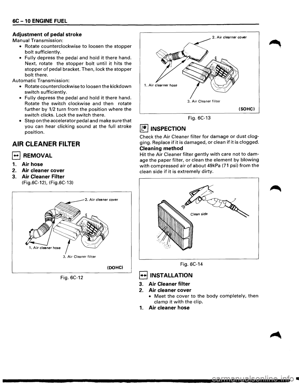
AIR CLEANER FILTER
EJ REMOVAL
1. Air hose
2. Air cleaner cover
3. Air Cleaner Filter
(Fig.6C-12), (Fig.6C-13)
2. Air cleaner cover
3. Air Cleaner filter
(DOHC)
Fig. 6C-12
2. Air clearner cover
3.
Air Cleaner filter
(SOHC)
Fig. 6C-13
~ INSPECTION
Check the Air Cleaner filter for damage or dust clog
ging. Replace if it is damaged, or clean if it is clogged.
Cleaning method
Hit the Air Cleaner filter gently with care not to dam
age the paper filter, or clean the element by blowing
with compressed air of about 49kPa (71 psi) from the
clean side if it is extremely dirty.
Fig. 6C-14
8 INSTALLATION
3. Air Cleaner filter
2. Air cleaner cover
• Meet the cover to the body completely, then
clamp it with the clip.
1. Air cleaner hose
•