brake light ISUZU TROOPER 1995 Repair Manual
[x] Cancel search | Manufacturer: ISUZU, Model Year: 1995, Model line: TROOPER, Model: ISUZU TROOPER 1995Pages: 1928
Page 657 of 1928
ENGINE ELECTRICAL 601-3
ON-VEHICLE SERVICE
BATTERY CHARGING
Observe the following safety precautions when
charging the battery:
1. Never attempt to charge the battery when the
fluid level is below the lower level line on the
side
of the battery. In this case, the battery
must be replaced.
2. Pay close attention to the battery during the
charging procedure.
Battery charging
should be discontinued or the
rate
of charge reduced if the battery feels hot
to the touch.
Battery charging
should be discontinued or the
rate
of charge reduced if the battery begins to
gas or spew electrolyte from the vent holes.
3. In order to more easily view the hydrometer
blue dot or ring, it may be necessary to jiggle
or tilt the battery.
4. Battery temperature can have a great effect on
battery charging capacity.
5. The sealed battery used on this vehicle may be
either quick-charged or slow-charged in the
same manner
as other batteries.
Whichever method you decide
to use, be sure
that you
completely charge the battery. Never
partially charge the battery.
JUMP STARTING
JUMP STARTING WITH AN AUXILIARY
(BOOSTER)
BATTERY
W CAUTION:
Never push or tow the vehicle in an attempt to
start it.
Serious damage to the emission sys
tem as
well as other vehicle parts will result.
Treat both the discharged battery and the
booster battery
with great care when using
jumper cables. Carefully follow the jump start
ing procedure, being
careful at all times to
avoid sparking.
wwARNING:
Failure to carefully follow the jump starting
procedure
could result in the following:
1. Serious personal injury, particulaly to your
eyes.
2. Property damage from a battery explo
sion, battery acid, or an electrical fire.
3. Damage to the electronic components of
one or both vehicles particularly.
Never expose the battery to an open flame or elec
trical
spark. Gas generated by the battery may catch
fire
or explode.
Remove any rings, watches, or other jewelry before
working around the battery. Protect
your eyes by
wearing
an approved set of goggles.
Never allow battery fluid to come in contact with
your eyes or skin.
Never
allow battery fluid to come in contact with
fabrics or painted surfaces.
Battery
fluid is a highly corrosive acid.
Should battery fluid come in contact with your eyes,
skin, fabric, or a painted surface,
immediately and
thoroughly rinse the affected area with clean tap
water. Never
allow metal tools or jumper cables to come
in contact with the positive battery
terminal, or any
other
metal surface of the vehicle. This will protect
against a short circuit.
Always keep batteries out of the reach of young
children.
JUMP STARTING PROCEDURE
1. Set the vehicle parking brake.
If the vehicle is equipped with an automatic
transmission,
place the selector lever in the
"PARK" position.
If the vehicle is equipped with a manual trans
mission
place the shift lever in the "NEUTRAL"
position.
Turn
"OFF" the ignition.
Turn
"OFF" all lights and any other accessory
requiring
electrical power.
2. Look at the built-in hydrometer.
If the indication area of the built-in hydrometer
is
completely clear, do not try to jump start.
3. Attach the end of one jumper cable to the posi
tive
terminal of the booster battery.
Attach the other end
of the same cable to the
positive
terminal of the discharged battery.
Do not allow the vehicles to touch each other.
This
will cause a ground connection, effectively
neutralizing
the charging procedure.
Be sure that the booster battery has a 12 volt
rating.
4. Attach one end of the remaining cable to the
negative
terminal of the booster battery.
Attach the other end
of the same cable to a
solid engine ground (such as the air condition
ing compressor bracket or the generator
mounting bracket)
of the vehicle with the dis
charged battery.
This ground connection must be at
least 450
mm (18 in) from the battery of the vehicle
whose battery is being charged.
Page 823 of 1928
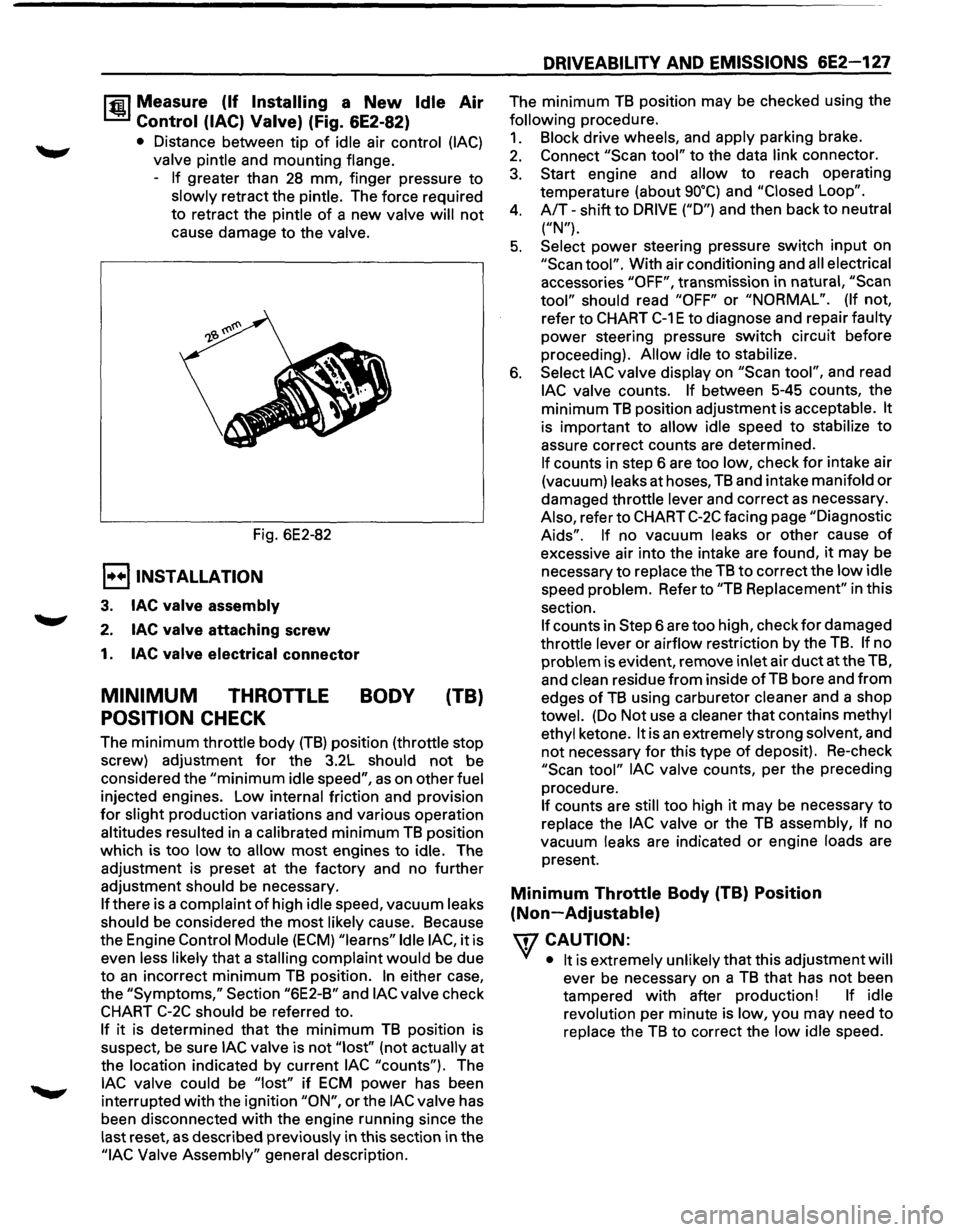
1~1 Measure (If Installing a New Idle Air
Control (lAC) Valve) (Fig. 6E2-82)
• Distance between tip of idle air control (lAC)
valve pintle and mounting flange.
-
If greater than 28 mm, finger pressure to
slowly retract the pintle. The force required
to retract the pintle
of a new valve will not
cause damage to the valve.
Fig. 6E2-82
E) INSTALLATION
3. lAC valve assembly
2. lAC valve attaching screw
1. lAC valve electrical connector
MINIMUM THROTTLE BODY (TB)
POSITION CHECK
The minimum throttle body (TB) position (throttle stop
screw) adjustment
for the 3.2L should not be
considered the
"minimum idle speed", as on other fuel
injected engines. Low internal friction and provision
for slight production variations and various operation
altitudes resulted in a calibrated
minimum TB position
which is too
low to allow most engines to idle. The
adjustment is preset at the factory and no further
adjustment should be necessary.
If there is a complaint of high idle speed, vacuum leaks
should be considered the
most likely cause. Because
the Engine
Control Module (ECM) "learns" Idle lAC, it is
even less likely
that a stalling complaint would be due
to
an incorrect minimum TB position. In either case,
the
"Symptoms," Section "6E2-B" and lAC valve check
CHART C-2C should be referred to.
If it is determined that the minimum TB position is
suspect,
be sure lAC valve is not "lost'' (not actually at
the location indicated by current
lAC "counts"). The
lAC valve could be "lost" if ECM power has been
interrupted
with the ignition "ON", or the lAC valve has
been disconnected
with the engine running since the
last reset,
as described previously in this section in the
"lAC Valve Assembly" general description.
DRIVEABILITY AND EMISSIONS 6E2-127
The minimum TB position may be checked using the
following procedure.
1. Block drive wheels, and apply parking brake.
2. Connect "Scan tool" to the data link connector.
3. Start engine and allow to reach operating
temperature (about
go•q and "Closed Loop".
4. A/T-shift to DRIVE ("D") and then back to neutral
("N").
5. Select power steering pressure switch input on
"Scan tool". With air conditioning and all electrical
accessories
"OFF", transmission in natural, "Scan
tool" should read "OFF" or "NORMAL". (If not,
refer to
CHART C-1 E to diagnose and repair faulty
power steering pressure switch circuit before
proceeding).
Allow idle to stabilize.
6. Select lAC valve display on "Scan tool", and read
lAC valve counts. If between 5-45 counts, the
minimum
TB position adjustment is acceptable. It
is important to allow idle speed to stabilize to
assure correct counts are determined.
If counts in step 6 are too low, check for intake air
(vacuum) leaks at hoses,
TB and intake manifold or
damaged throttle lever and correct as necessary.
Also, refer to
CHART C-2C facing page "Diagnostic
Aids". If no vacuum leaks or other cause of
excessive air into the intake are found, it may be
necessary
to replace the TB to correct the low idle
speed problem. Refer to
"TB Replacement" in this
section.
If counts in Step 6 are too high, check for damaged
throttle lever or airflow restriction by the
TB. If no
problem is evident, remove inlet air
duct at the TB,
and
clean residue from inside of TB bore and from
edges of TB using carburetor cleaner and a shop
towel. (Do Not use a cleaner that contains methyl
ethyl ketone.
It is an extremely strong solvent, and
not necessary for this type of deposit). Re-check
"Scan tool" lAC valve counts, per the preceding
procedure.
If counts are still too high it may be necessary to
replace the
lAC valve or the TB assembly, If no
vacuum leaks are indicated
or engine loads are
present.
Minimum Throttle Body (TB) Position
(Non-Adjustable)
\fl CAUTION:
VI • It is extremely unlikely that this adjustment will
ever be necessary on a TB that has not been
tampered
with after production! If idle
revolution per minute is low, you may need
to
replace the TB to correct the low idle speed.
Page 827 of 1928
DRIVEABILITY AND EMISSIONS 6E2-131
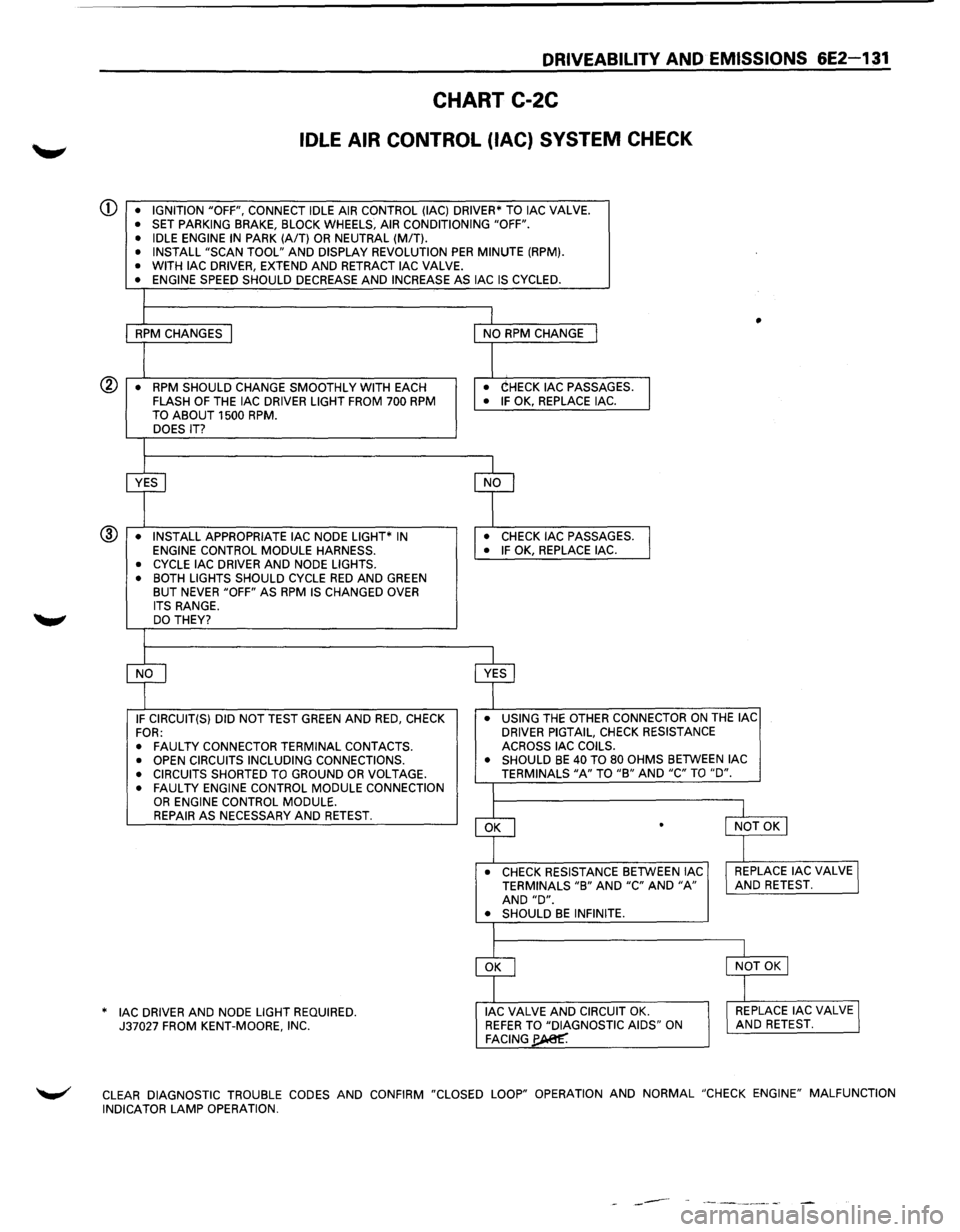
CHART C-2C
IDLE AIR CONTROL (lAC) SYSTEM CHECK
CD • IGNITION "OFF", CONNECT IDLE AIR CONTROL (lAC) DRIVER* TO lAC VALVE. • SET PARKING BRAKE, BLOCK WHEELS, AIR CONDITIONING "OFF".
• IDLE ENGINE IN PARK (A/T) OR NEUTRAL (MIT). • INSTALL "SCAN TOOL" AND DISPLAY REVOLUTION PER MINUTE (RPM). • WITH lAC DRIVER, EXTEND AND RETRACT lAC VALVE. • ENGINE SPEED SHOULD DECREASE AND INCREASE AS lAC IS CYCLED.
I
1 I • RPM CHANGES I NO RPM CHANGE I
I I • RPM SHOULD CHANGE SMOOTHLY
WITH EACH • CHECK lAC PASSAGES.
I FLASH OF THE lAC DRIVER LIGHT FROM 700 RPM • IF OK, REPLACE lAC.
TO ABOUT 1500 RPM. DOES IT?
I
~ cf
• INSTALL APPROPRIATE lAC NODE LIGHT* IN • CHECK lAC PASSAGES.
l ENGINE CONTROL MODULE HARNESS. • IF OK, REPLACE lAC. ®
• CYCLE lAC
DRIVER AND NODE LIGHTS.
• BOTH LIGHTS SHOULD CYCLE RED AND GREEN BUT NEVER "OFF" AS RPM IS CHANGED OVER
ITS RANGE. DO THEY?
I
cf ~ IF CIRCUIT(S) DID NOT TEST GREEN AND RED, CHECK •
USING THE OTHER CONNECTOR ON THE lAC
FOR: DRIVER
PIGTAIL, CHECK RESISTANCE
•
FAULTY CONNECTOR TERMINAL CONTACTS. ACROSS
lAC COILS.
• OPEN CIRCUITS INCLUDING CONNECTIONS. •
SHOULD BE 40 TO 80 OHMS BETWEEN lAC
• CIRCUITS SHORTED TO GROUND OR VOLTAGE. TERMINALS "A" TO "B" AND "C" TO "D".
• FAULTY ENGINE CONTROL MODULE CONNECTION I OR ENGINE CONTROL MODULE.
~
l REPAIR AS NECESSARY AND RETEST. l NOT OK I .
_l
• CHECK RESISTANCE BETWEEN lAC I REPLACE lAC VALVE I TERMINALS "B" AND "C" AND "A" AND RETEST. AND "D". • SHOULD BE INFINITE.
I
~
l
I NOT OK I
]
AC DRIVER AND NODE LIGHT REQUIRED. * I J lAC VALVE AND CIRCUIT OK. I REPLACE lAC VALVE J 37027 FROM KENT-MOORE, INC. REFER TO "DIAGNOSTIC AIDS" ON AND RETEST. FACING~
~ CLEAR DIAGNOSTIC TROUBLE CODES AND CONFIRM "CLOSED LOOP" OPERATION AND NORMAL "CHECK ENGINE" MALFUNCTION
INDICATOR LAMP OPERATION.
------
Page 883 of 1928

AUTOMATIC TRANSMISSION (4L30-E) 7 A-11
FUNCTIONS OF INPUT /OUTPUT COMPONENTS
Components Function
Speed sensor
Senses rotation
of output shaft and feeds the data to Transmission
(fixed
to transmission (T/M)) Control Module (TCM)
Throttle Senses the extent of throttle valve opening and the speed of the throttle
position sensor (TPS) valve lever motion to open the valve and feeds the data to TCM (fed to
(fixed to engine)
Engine Control Module (ECM) also)
I
Brake Switch (SW) Senses whether the driver has pressed the brake pedal or not and feeds
N (fixed
to brake pedal) the
information to TCM
p Kick-down SW (fixed to Senses whether the driver has pushed the accelerator pedal fully or not
u accelerator pedal) and feeds the information to TCM
T Mode
SW (fixed to T/M) Senses the select lever position and feeds the information to TCM
s Power drive SW Senses whether the driver has selected the power mode and feeds the
I (fixed to front console) information to TCM
G T/M
oil temp. sensor
Senses the T/M oil temperature and feeds the data to TCM
N Engine
coolant Senses the engine cooling water temperature and feeds the data to TCM
A temperature
SW (feeds the signal from ECM)
L
Engine speed
signal Feeds the signals monitoring engine speed to TCM from Ignition Control
Module
(fed to ECM also)
Air conditioning Senses whether the air conditioner has been switched on or not and
information feeds the information
to TCM
On-board diagnostic
input By monitoring the Ground (GND), the location of failure is shown on the
T/M
monitor lamp ("CHECK TRANS") by flashing the diagnostic trouble
code
Winter switch
Senses whether the driver has selected the winter mode, and feeds the
(fixed
to front console) information to TCM
Cruise
controller Downshift takes place when Overdrive OFF signal is received from auto
(Overdrive
OFF signal) cruise control unit
Shift
solenoid Selects shift point and gear position suited to the vehicle running con-s 1-2/3-4, 2-3
dition on the basis of TCM output 0 Band apply solenoid
Controls oil flow suited to the vehicle running condition on the basis of L
E TCM output
0 N
Torque
Converter Controls clutch engagement/disengagement suited to the vehicle
u 0 Clutch solenoid running condition on the basis of TCM output
T I Force motor Adjusts the oil pump delivery pressure to line pressure suited to the p D
(Pressure regulator vehicle running condition on the basis of TCM output u valve) T
Power drive mode lamp
Informs the driver whether the vehicle is in power mode or not
s Winter drive mode lamp Informs the driver whether the vehicle is in winter mode or not
I T/M monitor lamp Informs the driver of failure in the system. It also displays the self diagnosis
G
("CHECK TRANS") code.
N Data Link Connector
(DLC) When connected with TECH 1 or tester, can communicate the data for A
L function
check, etc. (fed to ECM also). When TECH 1 is not connected, can
communicate the
signal for torque management with ECM.
Self-diagnosis connector
When short-circuited with the bipolar connector, the T/M monitor lamp
displays
a failure by code.
ATF warning
lamp Lights when ATF oil temperature rises.
ABS signal When the select lever is at "Reverse" or "L" range, sends a signal to the
ABS controller as one of the ABS control conditions.
Page 892 of 1928
7 A-20 AUTOMATIC TRANSMISSION (4L30-E)
CHECKING TRANSMISSION FLUID
LEVEL AND CONDITION
Checking fluid level and condition (color and odor)
at
regular intervals will provide early diagnosis
information about the transmission. This inform
ation may be used to correct a condition that, if not
detected early, could result in major transmission
repairs.
IMPORTANT: When new, automatic transmission
fluid is red in color. As the vehicle is driven, the
transmission
fluid will begin to look darker in color.
The
color may eventually appear light brown.
A DARK
brown color with burnt odor may indicate
excessive
fluid deterioration and signal a need for
fluid change.
FLUID LEVEL
When adding
or changing fluid, use only DEXRON
®-Ill.
Refer to the Maintenance and Lubrication (Section 0
of this manual) for maintenance information and
servicing
interval.
\f CAUTION: DO NOT OVERFILL
Overfilling will cause foaming, loss ~f fluid,
abnormal shifting and possible damage to
the transmission.
1. Start engine and drive vehicle until normal AfT
oil operating temperature is reached:
NOTE: The automatic transmission fluid level
must be checked with the vehicle at normal
A/T oil operating temperature: 75 TO 85°C
(167 TO 185°F) MEASURED WITH TECH1 SCAN
TOOL.
Temperature will greatly affect transmission
fluid level.
If the vehicle is not at normal AfT oil operating
temperature and the proper checking
procedures are
not followed, the result could
be a false reading of the fluid level indicator
and
an incorrect adjustment of the fluid level.
2. Park vehicle on level ground.
3. Move gear selector to "Park".
4. Apply parking brake and block wheels.
5. Allow vehicle to idle for 3 minutes with all
accessories turned off.
6. Check fluid level with engine running at idle:
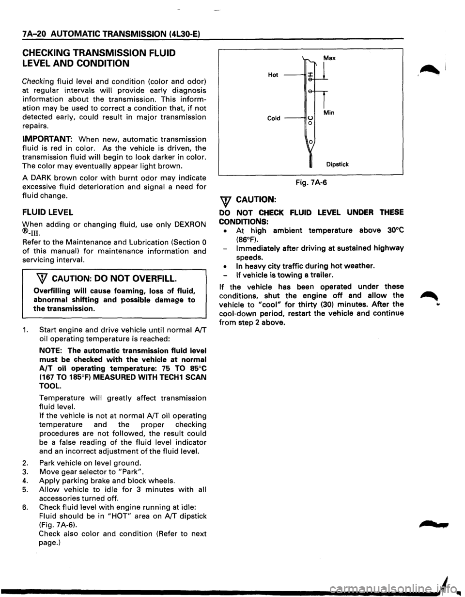
Fluid should
be in "HOT" area on AfT dipstick
(Fig. 7A-6).
Check also color and condition (Refer to next
page.)
Hot
Cold ---IIU 0
0
Min
Dipstick
Fig. 7A-6
\f CAUTION:
DO NOT CHECK FLUID LEVEL UNDER THESE
CONDITIONS: •
At high ambient temperature above 30°C
(86°F).
Immediately after driving at sustained highway
speeds.
• In heavy city traffic during hot weather.
If vehicle is towing a trailer.
If the vehicle has been operated under these
conditions,
shut the engine off and allow the
vehicle to "cool" for thirty (30) minutes. After the
cool-down period, restart the vehicle and continue
from step 2 above.
'~I
......
Page 1000 of 1928
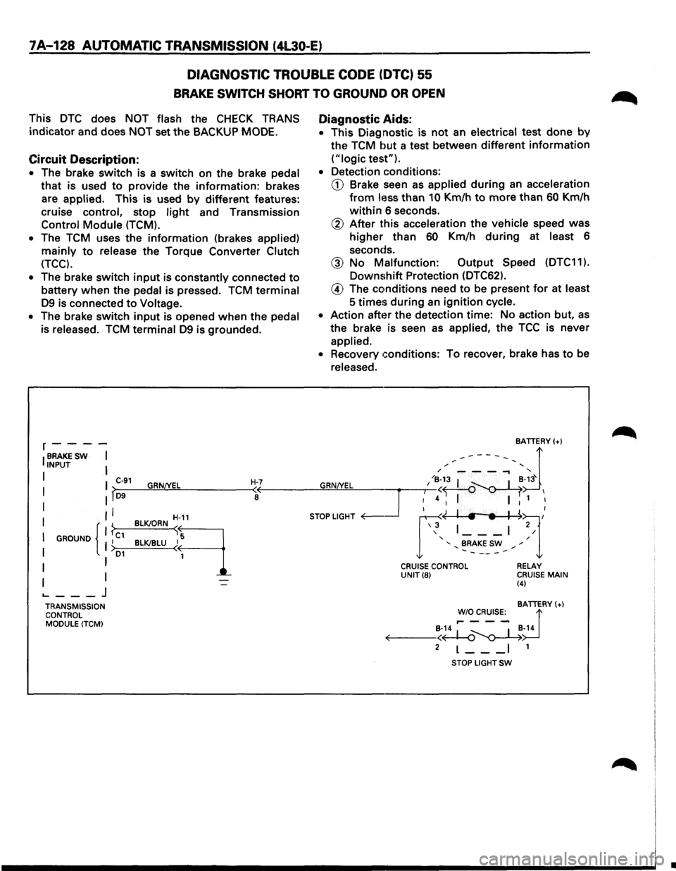
7A-128 AUTOMATIC TRANSMISSION (4L30-E)
DIAGNOSTIC TROUBLE CODE (DTC) 55
BRAKE SWITCH SHORT TO GROUND OR OPEN
This DTC does NOT flash the CHECK TRANS
indicator and does NOT set the BACKUP MODE.
Circuit Description:
• The brake switch is a switch on the brake pedal
that is used to provide the information: brakes
are
applied. This is used by different features:
cruise control, stop
light and Transmission
Control Module (TCM).
•
The TCM uses the information (brakes applied)
mainly to release the Torque Converter Clutch
(TCC).
•
The brake switch input is constantly connected to
battery when the pedal is pressed. TCM terminal
D9 is connected to Voltage.
• The brake switch input is opened when the pedal
is released.
TCM terminal D9 is grounded.
r----
IBRAKESW I INPUT I
I I C-91 GRN/YEL H-7 I >-D9--~~~------~<
I II a
II
I GROUND I C1 I { }
I I >D1
I I
I I ._ ___ j
TRANSMISSION
CONTROL
MODULE (TCM) BLK!ORN
~-11
B~LU~q
Diagnostic
Aids:
• This Diagnostic is not an electrical test done by
the TCM but a test between different information
("logic test").
• Detection conditions:
CD Brake seen as applied during an acceleration
from less than 10 Km/h to more than 60 Km/h
within 6 seconds.
@ After this acceleration the vehicle speed was
higher than 60 Km/h during at least 6
seconds.
@ No Malfunction: Output Speed (DTC11 ).
Downshift Protection (DTC62).
@ The conditions need to be present for at least
5
times during an ignition cycle.
• Action after the detection time: No action but, as
the brake is seen as applied, the TCC is never
applied.
• Recovery conditions: To recover, brake has to be
released.
CRUISE CONTROL UNIT(8) RELAY
CRUISE MAIN (4)
BATTERY(+)
!'~~s:_ d B-14 ~ _ I _B-14 ~--<~~
2 L--_I 1
STOP LIGHT SW
•
Page 1002 of 1928
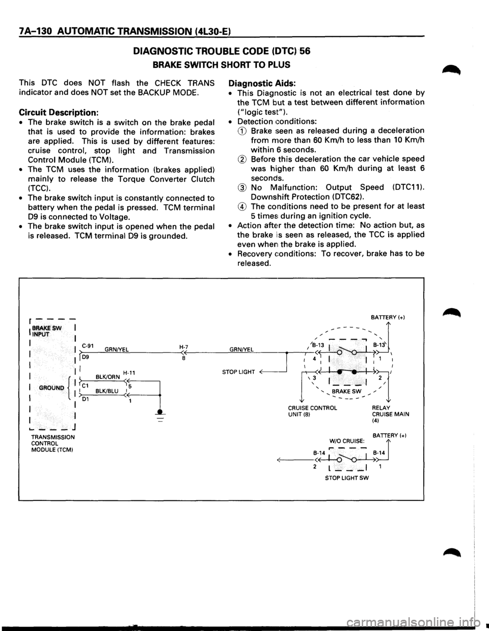
7A-130 AUTOMATIC TRANSMISSION (4l30-E)
DIAGNOSTIC
TROUBLE CODE (DTC)·56
BRAKE SWITCH SHORT TO PLUS
This DTC does NOT flash the CHECK TRANS
indicator and does
NOT set the BACKUP MODE.
Circuit Description:
• The brake switch is a switch on the brake pedal
that is used to provide the information: brakes
are
applied. This is used by different features:
cruise
control, stop light and Transmission
Control Module (TCM).
•
The TCM uses the information (brakes applied)
mainly to release the Torque Converter Clutch
(TCC).
• The brake switch input is constantly connected to
battery when the pedal is pressed. TCM terminal
D9 is connected to Voltage.
•
The brake switch input is opened when the pedal
is released. TCM terminal D9 is grounded.
r----
IBRAKESW I INPUT I
I I C-91 GRN!YEL H-7 I lf~D-9--~~~------~~
I II I
I GROUND { 1 ?c1 II I >o1
I I
I I
.._ ___ J
TRANSMISSION
CONTROL
MODULE (TCM)
H-11
BLK!ORN sq
BLK!BLU ~
1
Diagnostic Aids:
• This Diagnostic is not an electrical test done by
the TCM but a test between different information
("logic test").
•
Detection conditions:
CD Brake seen as released during a deceleration
from more than 60 Km/h to less than 10 Km/h
within 6 seconds.
® Before this deceleration the car vehicle speed
was
higher than 60 Km/h during at least 6
seconds.
@ No Malfunction: Output Speed (DTC11).
Downshift Protection (DTC62).
@ The conditions need to be present for at least
5 times; during an ignition cycle.
•
Action atte~r the detection time: No action but, as
the brake is seen as released, the TCC is applied
even when the brake is applied.
•
Recovery conditions: To recover, brake has to be
released.
BATTERY(+)
,.------, d / '
GRN/YEL I /~;3 I ~-~3' I
~4 I I 1 I
STOP LIGHT <0---.Jr ~~l/ \3 1 ___ , 2/
' / ' BRAKE SW ,. .......... -----.......
CRUISE CONTROL UNIT(8) RELAY CRUISE MAIN (4)
BATTERY(+)
~~~R~s:_ d
·:.:-: ---~~~-14
2 L--_I 1
STOP LIGHT SW
•
Page 1016 of 1928
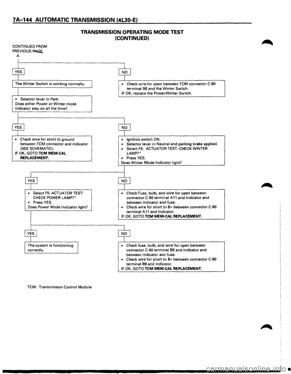
7A-144 AUTOMATIC TRANSMISSION (4L30-E)
TRANSMISSION OPERATING MODE TEST
(CONTINUED)
CONTINUED FROM
PREVIOUS
PAGE. A
I
$
The Winter Switch is working normally.
I
• Selector lever in Park .
Does
either Power or Winter mode indicator stay on all the time?
I
$
• Check wire for short to ground
between
TCM connector and indicator (SEE SCHEMATIC).
IF OK, GOTO TCM MEM-CAL REPLACEMENT.
$
• Select F5: ACTUATOR TEST: CHECK POWER LAMP?"
• Press YES .
Does Power Mode Indicator light?
~
The system is functioning
J correctly.
TCM:
Transmission Control Module
$
• Check wire for open between TCM connector C-90 terminal 86 and the Winter Switch.
IF OK, replace the Power/Winter Switch.
$
• Ignition switch ON .
• Selector lever in Neutral and parking brake applied .
• Select F5: ACTUATOR TEST: CHECK WINTER
LAMP?"
• Press YES .
Does Winter Mode Indicator light?
I
$
• Check Fuse, bulb, and wire for open between
connector C-90 terminal A 11 and indicator and
between indicator and fuse.
• Check wire for short til 8+ between connector C-90
terminal A 11 and Indicator. IF OK, GOTO TCM MEM-CAL REPLACEMENT.
$
• Check fuse, bulb, and wire for open between
connector C-90 terminal 89 and indicator and
between indicator andl fuse.
• Check wire for short to 8+ between connector C-90 terminal 89 and indicator.
IF OK, GOTO TCM MEM-CAL REPLACEMENT.
•
Page 1022 of 1928
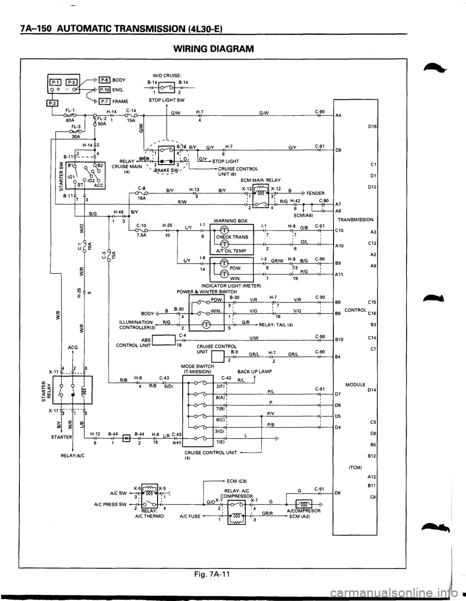
7A-150 AUTOMATIC TRANSMISSION (4L30-E)
WIRING DIAGRAM
L--<~o-~~~~~~--~~~----~~~----~~--------------~G"IW~------------C«-9_0--iA4
D16
30A
D12
GfY ---~:at--B-'li BfY G(Y H-7 ,...-..~., 4,' ~ ~
RELAY ~' ~:iO 1 [my_ STOP LIGHT
2 3 I CRUISE MAIN '..BRAKES '' L------•CRUISE CONTROL (4) - ---vy UNIT (8) D1
~2
8-11+~---f4
~ 81~ Q._ ("'~2
~ IG1 18~ ~ ST ACC en 8-11
C-91 D9
C1
ECM MAIN RELAY
X-f~ ~X~~2 8 II• FENDER R/W : - : RiG H-42 C-90 '-----t--t------+-------!:!Lll----------< • ~( r fl A7 2 4 8 L....{+--AS
C-8
~A
H-13 BfY BfY 3 7 3
L-+-JB~~I,_IG __ __....,~4-B(Y ECM(A61 1 3 WARNING BOX TRANSMISSION
~T'~5'-'1:D----H-+~2~5 LfY ~~~ ~K TRANS 1-,17 Hr7 :~ C-~1 C10 C::
0 ~
"' <( u :!?
'----~
"' ":' 0'> J:
IXl ~ a: ~
I~ A10 AJT OIL TEMP 2
8
A
2
LfY 1-9~ ~1-9 GR/W H;9 BiG C-90 89 1~ POW. : 8 ~3 , A9
- -~· PiG c(-A11 WIN. 7 19 INDICATOR LIGHT (METER) POWER & WINTER SWITCH
_,. POW. 8-30 ViR H-,>,7:;-----'V"-'iR.!..,_ ___ c<-~9-0-l B8 C15 II-v 3, :7 • BODY of~~ ~-o-WIN. 1 ,' ViG -----.+.,.,176 __ ____;;V.:..;iG=-----<+'-----1 B
6 CONTROL C16 ,4 ILLUMINATION~' ~ '~RELAY: TAIL (4) CONTROLLER(3) 2 -~ 5
ABS ~c~4----------------__yV:J..:!:!._/W ______________ ___:C<-~9:..::0-l B 10 CONTROL UNIT 16 CRUISE CONTROL
RiB H-8 C-43
4 RiB 5(D)
UNIT Q;·>-9------"G,_,Ri_,L_~:+--;-----'G""R""iL::,_ ___ c,-+-9-0----j 84
MODE SWITCH
IT-MISSION)
C-43
2(F) ~ ' 8(A), '
BACKUP LAMP
RiL
t
PiL
p
C-91 ( D7 : D6
B3
C14
C7
MODULE D14
: D5 : C5 ( D4 C6
B5
7(B)'
X-17-l-~J,-~L -v-: 6((:1§': :
r! -v-u-3tGi'', STARTER H-~..._:4---4r::J-Mo~-_B~;~;8 LJR C;~434--o-_,_-o---+---<·' L ---1 8 1 [::::J 2 15 4(H) u---~< 1 '
CRUISE CONTROL UNIT RELAY;A/C (4)
DB
(TCM) 812
A12
811
C8
....
'
Fig.7A·11 I
------------------------~~
•
Page 1024 of 1928
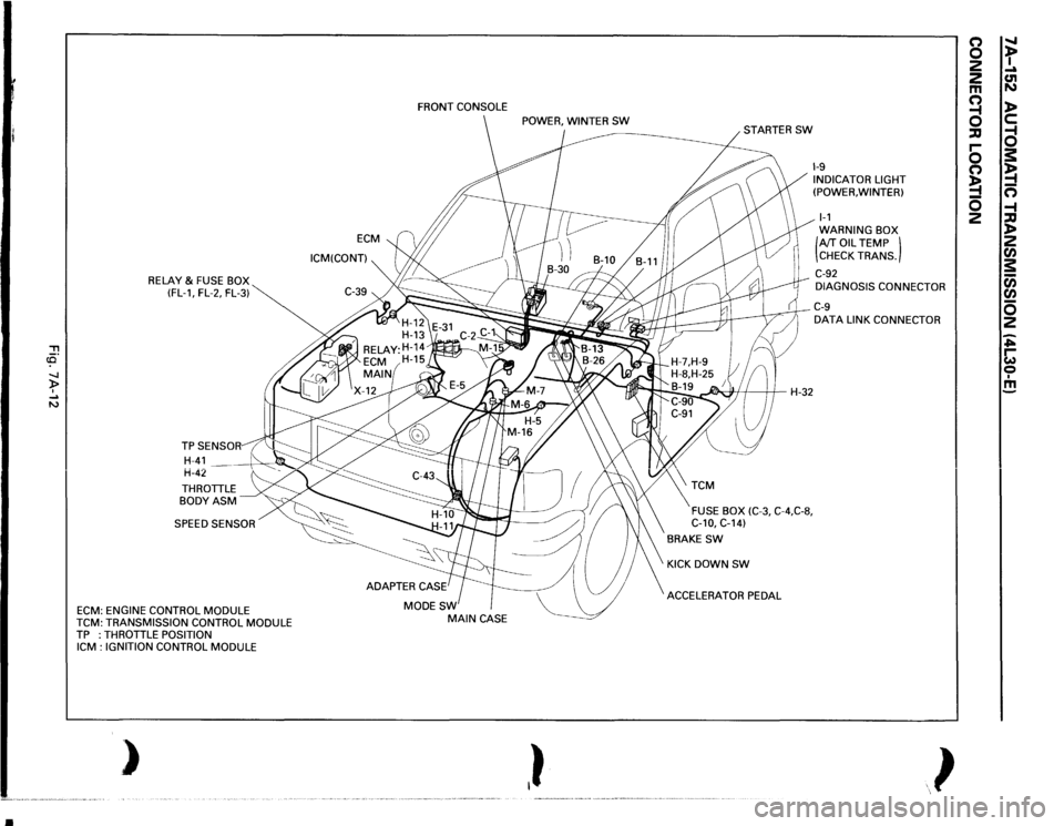
•
, cCi" -.J )> I .... N
RELAY
& FUSE BOX
(FL-1, FL-2, FL-3)
THROTTLE BODYASM SPEED SENSOR
ECM:
ENGINE CONTROL
MODULE
TCM:
TRANSMISSION CONTROL
MODULE
TP :THROTTLE
POSITION
ICM
: IGNITION CONTROL
MODULE
)
ECM
ICM(CONT) FRONT
CONSOLE
MODESW
MAIN
CASE
,}
~H-32
FUSE BOX
(C-3,
C-4,C-8,
C-10,
C-14)
BRAKE
SW
KICK DOWN
SW
ACCELERATOR PEDAL
1-9 INDICATOR LIGHT
(POWER, WINTER) 1-1 WARNING BOX (AfT
OIL
TEMP )
CHECK TRANS.
C-92 DIAGNOSIS CONNECTOR C-9 DATA
LINK CONNECTOR
}
(') 0 2
2 m a ::IJ r-0 (') !4 0 2
" t .... C1l N l> c: a s: !4 n -4 ::IJ l> 2 rA s: c;; rA 0 2 ~ ~ 0 I m