instrument panel ISUZU TROOPER 1995 Workshop Manual
[x] Cancel search | Manufacturer: ISUZU, Model Year: 1995, Model line: TROOPER, Model: ISUZU TROOPER 1995Pages: 1928
Page 14 of 1928
OA-10 GENERAL INFORMATION
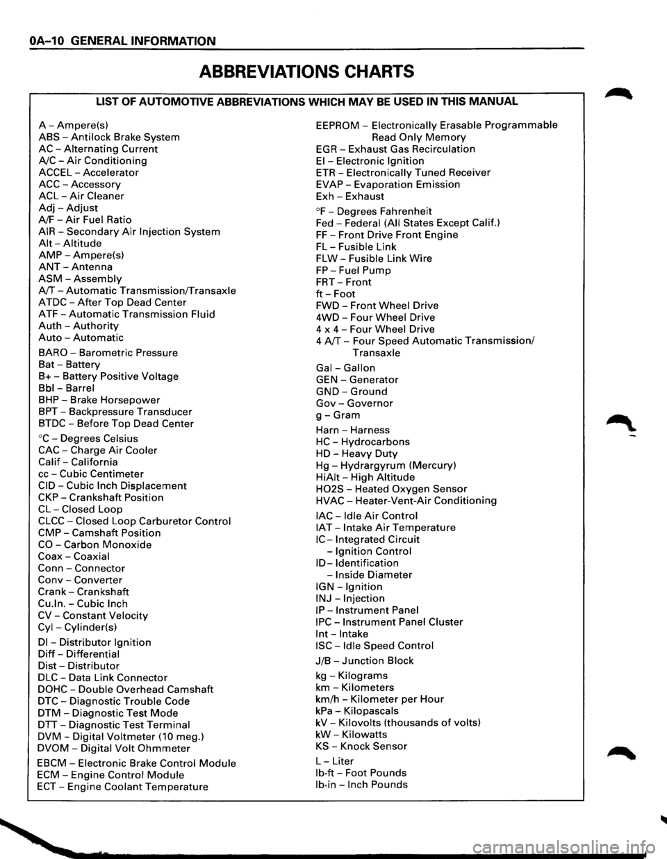
ABBREVIATIONS CHARTS
LIST OF AUTOMOTIVE ABBREVIATIONS WHICH MAY BE USED IN THIS MANUAL
A-Ampere(s)
ABS-Anti lock Brake System
AC-Alternating Current
A/C-Air Conditioning
ACCEL-Accelerator
ACC-Accessory
ACL-Air Cleaner
Adj-Adjust
A/F-Air Fuel Ratio
AIR-Secondary Air Injection System
Alt-Altitude
AMP-Ampere(s)
ANT-Antenna
ASM-Assembly
A/T-Automatic Transmission/Transaxle
ATDC-After Top Dead Center
ATF-Automatic Transmission Fluid
Auth -Authority
Auto -Automatic
BARO-Barometric Pressure
Bat -Battery
B+-Battery Positive Voltage
Bbl-Barrel
BHP-Brake Horsepower
BPT-Backpressure Transducer
BTDC-Before Top Dead Center
oc-Degrees Celsius
CAC-Charge Air Cooler
Calif-California
cc-Cubic Centimeter
CID-Cubic Inch Displacement
CKP-Crankshaft Position
CL-Closed Loop
CLCC-Closed Loop Carburetor Control
CMP-Camshaft Position
CO-Carbon Monoxide
Coax-Coaxial
Conn-Connector
Conv -Converter
Crank-Crankshaft
Cu.ln.-Cubic Inch
CV-Constant Velocity
Cyl-Cylinder(s)
Dl -Distributor Ignition
Diff-Differential
Dist-Distributor
DLC-Data Link Connector
DOHC-Double Overhead Camshaft
DTC-Diagnostic Trouble Code
DTM-Diagnostic Test Mode
DTT-Diagnostic Test Terminal
DVM-Digital Voltmeter (10 meg.)
DVOM-Digital Volt Ohmmeter
EBCM-Electronic Brake Control Module
ECM-Engine Control Module
ECT-Engine Coolant Temperature
EEPROM -Electronically Erasable Programmable
Read Only Memory
EGR-Exhaust Gas Recirculation
El-Electronic Ignition
ETR-Electronically Tuned Receiver
EVAP-Evaporation Emission
Exh-Exhaust
°F-Degrees Fahrenheit
Fed -
Federal (All States Except Calif.)
FF-Front Drive Front Engine
FL-Fusible Link
FLW-Fusible Link Wire
FP-Fuel Pump
FRT-Front
ft-Foot
FWD-Front Wheel Drive
4WD-Four Wheel Drive
4 x
4-Four Wheel Drive
4 A/T-Four Speed Automatic Transmission/
Transaxle
Gal-Gallon
GEN-Generator
GND-Ground
Gov-Governor
g-Gram
Harn -Harness
HC-Hydrocarbons
HD-Heavy Duty
Hg-Hydrargyrum (Mercury)
HiAit-High Altitude
H02S - Heated Oxygen Sensor
HVAC-Heater-Vent-Air Conditioning
lAC-Idle Air Control
IAT -Intake Air Temperature
IC-Integrated Circuit
-
Ignition Control
ID-Identification
-Inside Diameter
IGN-Ignition
INJ-Injection
IP-Instrument Panel
IPC-Instrument Panel Cluster
lnt-Intake
ISC-Idle Speed Control
J/B-Junction Block
kg -Kilograms
km-Kilometers
km/h -Kilometer per Hour
kPa-Kilopascals
kV-Kilovolts (thousands of volts)
kW-Kilowatts
KS -Knock Sensor
L-Liter
lb·ft-Foot Pounds
lb·in-Inch Pounds
Page 41 of 1928
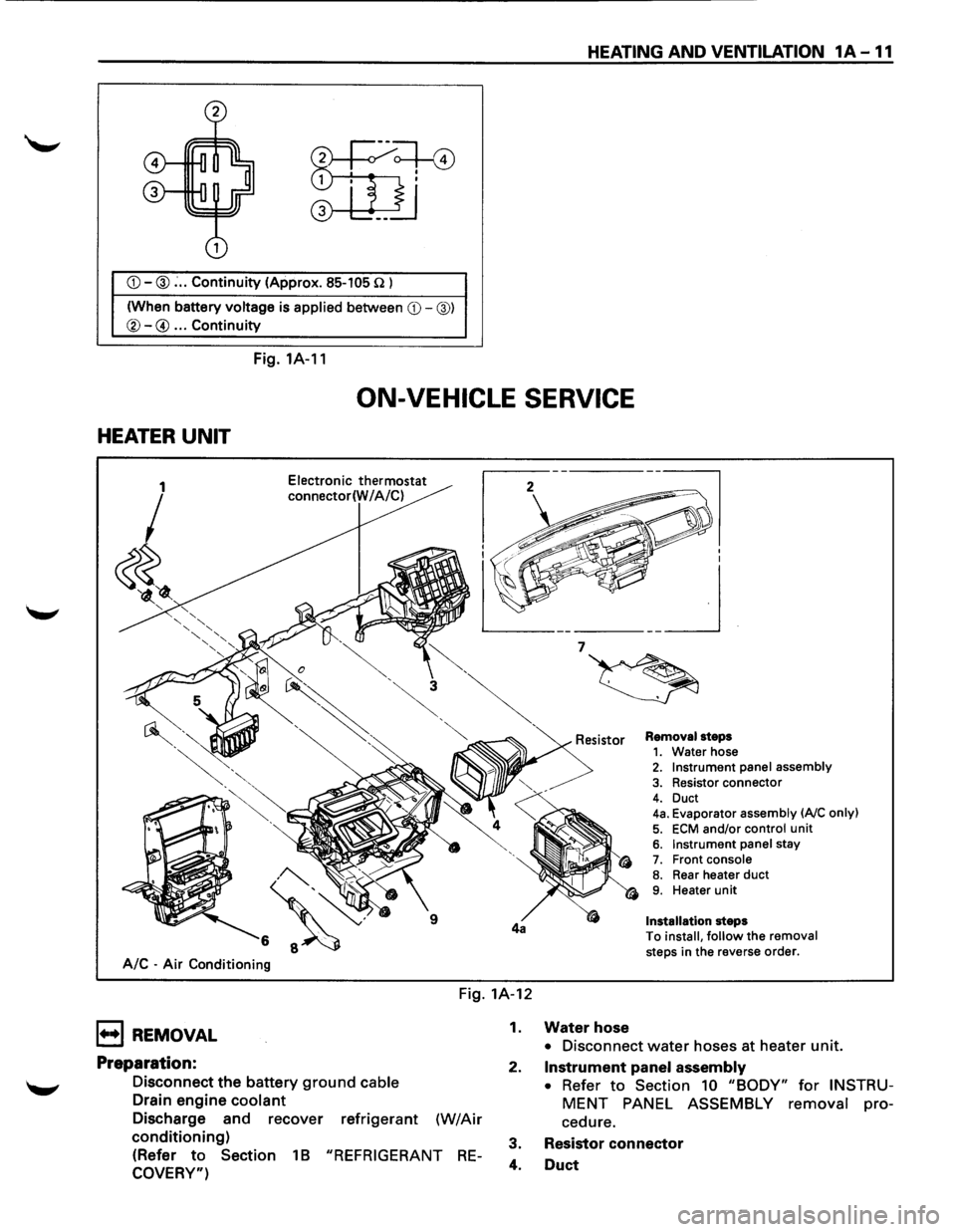
CD-@: .. Continuity (Approx. 85-105 n l
(When battery
voltage is applied between CD-@)
®-@ ... Continuity
Fig. 1A-11
HEATING AND VENTILATION 1A -11
ON-VEHICLE SERVICE
HEATER UNIT
A/C -Air Conditioning
Electronic thermostat
connector(W I A/C)
Removal steps 1. Water hose 2. Instrument panel assembly
3. Resistor connector
4. Duct 4a. Evaporator assembly (AJC only)
5. ECM and/or control unit 6. Instrument panel stay 7. Front console 8. Rear heater duct 9. Heater unit
Installation steps
To
install, follow the removal
steps in the reverse order.
Fig. 1A-12
1••1 REMOVAL
Preparation:
Disconnect the battery ground cable
Drain engine coolant
Discharge and recover refrigerant (W/Air
conditioning)
(Refer to Section 1 B "REFRIGERANT RE
COVERY")
1. Water hose
• Disconnect water hoses at heater unit.
2.
Instrument panel assembly
• Refer to Section 10 "BODY" for INSTRU
MENT PANEL ASSEMBLY removal pro
cedure.
3. Resistor
connector
4. Duct
Page 42 of 1928
1A ";" 12 HEATING AND VENTILATION
4a. Evaporator assembly
• Refer to Section 1 B "AIR CONDITIONING" for
Evaporator Assembly removal procedure.
5. ECM and/or control unit
• Do not disconnect ECM and control unit
connectors.
6. Instrument panel stay
7. Front console
8. Rear heater duct
9. Heater unit
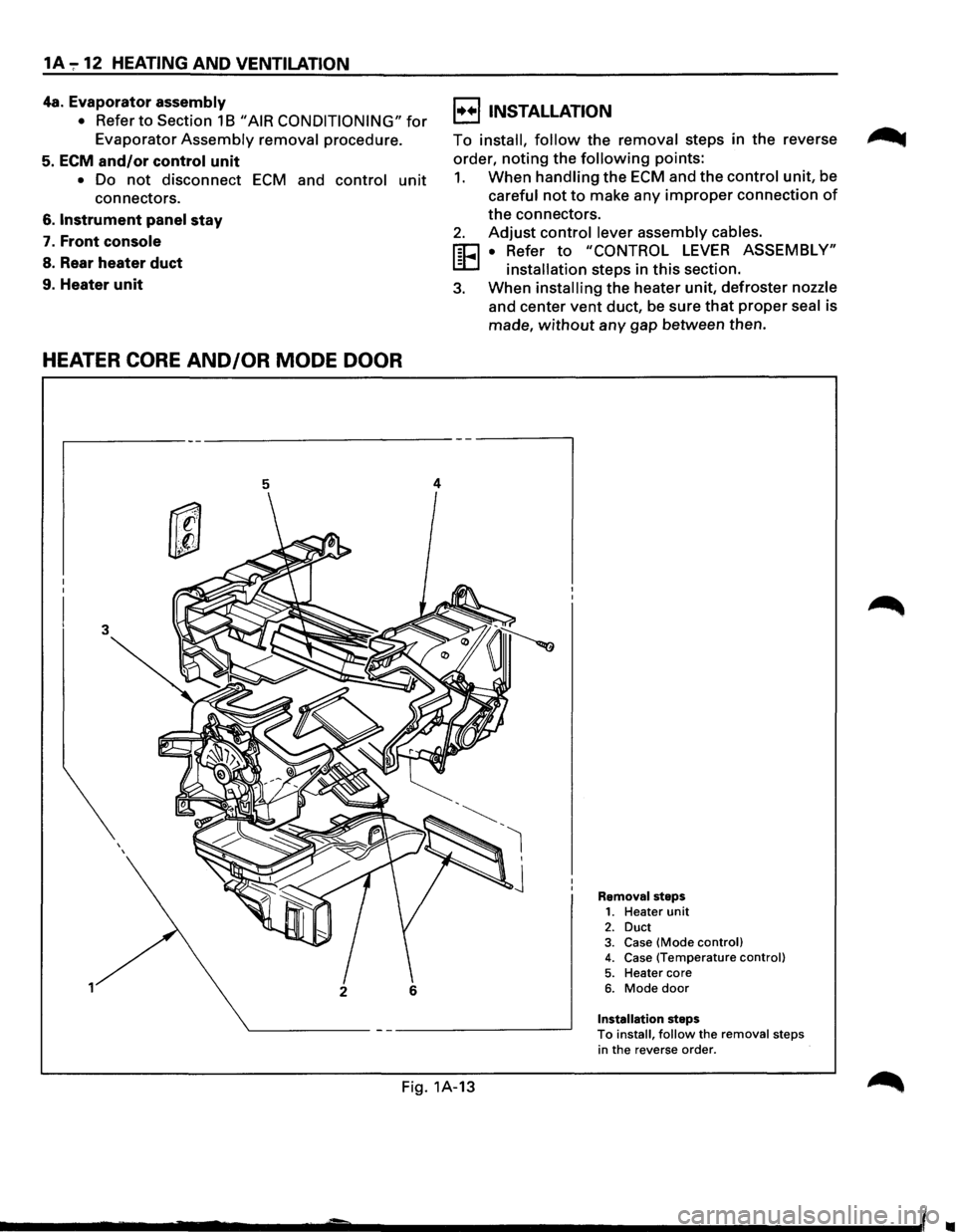
HEATER CORE AND/OR MODE DOOR
3
1
5
2 6
4
I••! INSTALLATION
To install, follow the removal steps in the reverse
order,
noting the following points:
1. When handling the ECM and the control unit, be
careful not to make any improper connection of
the connectors.
2. Adjust control lever assembly cables.
FEI • Refer to "CONTROL LEVER ASSEMBLY"
-installation steps in this section.
3. When installing the heater unit, defroster nozzle
and center vent duct, be sure that proper seal is
made,
without any gap between then.
Removal steps 1. Heater unit 2. Duct 3. Case (Mode control) 4. Case (Temperature control)
5. Heater core 6. Mode door
Installation steps To install, follow the removal steps
in the reverse order.
Fig. 1A-13
..
Page 46 of 1928
1A-16 HEATING AND VENTILATION
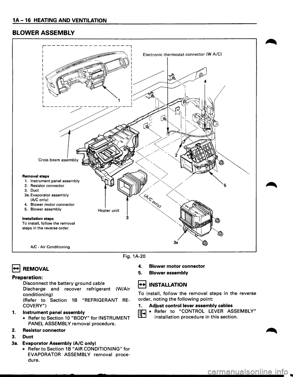
BLOWER ASSEMBLY
Cross beam assembly
Removal steps
1. Instrument panel assembly 2. Resistor connector
3. Duct 3a. Evaporator assembly
lAIC only)
4. Blower motor connector 5. Blower assembly
Installation
steps
To install, follow the removal steps in the reverse order.
A/C -Air Conditioning Heater
unit
Electronic thermostat connector (W A/C)
5
3
3a
Fig.
1A-20
1+•1 REMOVAL
Preparation:
Disconnect the battery ground cable
Discharge and recover refrigerant (W/Air
conditioning)
(Refer to Section 1B "REFRIGERANT RE
COVERY")
1. Instrument panel assembly
• Refer to Section 10 "BODY" for INSTRUMENT
PANEL ASSEMBLY removal
procedure.
2. Resistor connector
3. Duct
3a. Evaporator Assembly (A/C only)
• Refer to Section 1B "AIR CONDITIONING" for
EVAPORATOR ASSEMBLY removal proce
dure.
4. Blower motor connector
5. Blower assembly
I••IINSTALLATION
To install, follow the removal steps in the reverse
order,
noting the following point:
1. Adjust control lever assembly cables
r:C1 • Refer to "CONTROL LEVER ASSEMBLY"
L.:D installation procedure in this section.
Page 49 of 1928
HEATING AND VENTILATION 1A-19
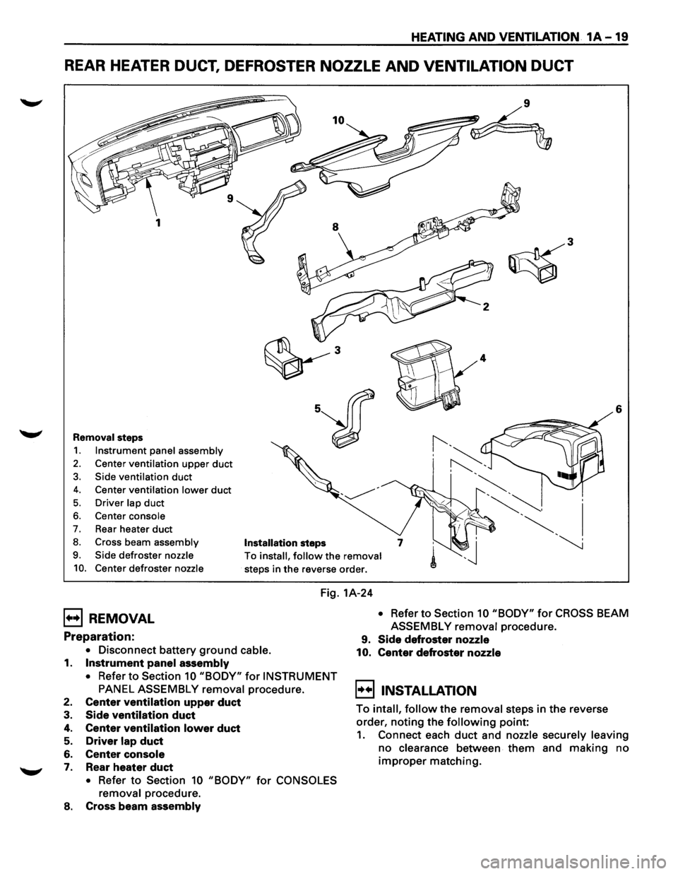
REAR HEATER DUCT, DEFROSTER NOZZLE AND VENTILATION DUCT
6
Removal steps
1. Instrument panel assembly
2. Center ventilation upper duct
3. Side ventilation duct
4. Center ventilation lower duct
5. Driver lap duct
6. Center console
7. Rear heater duct
8. Cross beam assembly Installation steps
9. Side defroster nozzle
10. Center defroster nozzle
To install, follow the removal
steps in the reverse order.
Fig. 1A-24
B REMOVAL
Preparation:
• Disconnect battery ground cable.
1. Instrument panel assembly
• Refer to Section 10 "BODY" for INSTRUMENT
PANEL ASSEMBLY removal procedure.
2. Center ventilation upper duct
3. Side ventilation duct
4. Center ventilation lower duct
5. Driver lap duct
6. Center console
7. Rear heater duct
• Refer to Section 10 "BODY" for CONSOLES
removal
procedure.
8. Cross beam assembly
• Refer to Section 10 "BODY" for CROSS BEAM
ASSEMBLY
removal procedure.
9. Side defroster nozzle
10. Center defroster nozzle
~!!) INSTALLATION
To intall, follow the removal steps in the reverse
order,
noting the following point:
1. Connect each duct and nozzle securely leaving
no clearance between them and making no
improper matching.
Page 50 of 1928
1A-20 HEATING AND VENTILATION
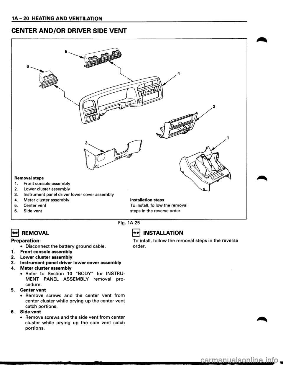
CENTER AND/OR DRIVER SIDE VENT
5
6
' -~
'
"
Removal steps
1. Front console assembly
2. Lower cluster assembly
3. Instrument panel driver lower cover assembly
4. Meter cluster assembly
5. Center vent
6. Side vent
4
Installation steps
To install, follow the removal
steps in the reverse order.
2
1
Fig. 1A-25
B REMOVAL
Preparation:
• Disconnect the battery ground cable.
1. Front console assembly
2. Lower cluster assembly
3. Instrument panel driver lower cover assembly
4. Meter cluster assembly
•
Refer to Section 10 "BODY" for INSTRU
MENT PANEL ASSEMBLY removal pro-
cedure.
5. Center vent
• Remove screws and the center vent from
center cluster while prying up the center vent
catch portions.
6. Side vent
• Remove screws and the side vent from center
cluster while prying up the side vent catch
portions.
E] INSTALLATION
To intall, follow the removal steps in the reverse
order.
..
Page 51 of 1928
HEATING AND VENTILATION 1A-21
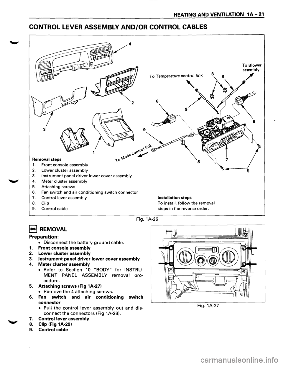
CONTROL LEVER ASSEMBLY AND/OR CONTROL CABLES
2
3
~ 1
Removal steps
1. Front console assembly
2. Lower cluster assembly
3. Instrument panel driver lower cover assembly
4. Meter cluster assembly
5. Attaching screws
6. Fan switch and air conditioning switch connector
7. Control lever assembly
8. Clip
9.
Control cable
6
' '
Installation steps
To install, follow the removal
steps in
the reverse order.
Fig. 1A-26
B REMOVAL
Preparation:
• Disconnect the battery ground cable.
1.
Front console assembly
2. Lower cluster assembly
3. Instrument panel driver lower cover assembly
4. Meter cluster assembly
• Refer to Section 10 "BODY" for INSTRU
MENT PANEL ASSEMBLY removal pro
cedure.
5. Attaching screws (Fig 1A-27)
• Remove the 4 attaching screws.
6. Fan switch and air conditioning switch
connector
• Pull the control lever assembly out and dis-
connect the connectors (Fig 1A-28).
7. Control lever assembly
8. Clip (Fig 1A-29)
9.
Control cable
Fig. 1A-27
To Blower
assembly
6
Page 82 of 1928
1 B-28 AIR CONDITIONING
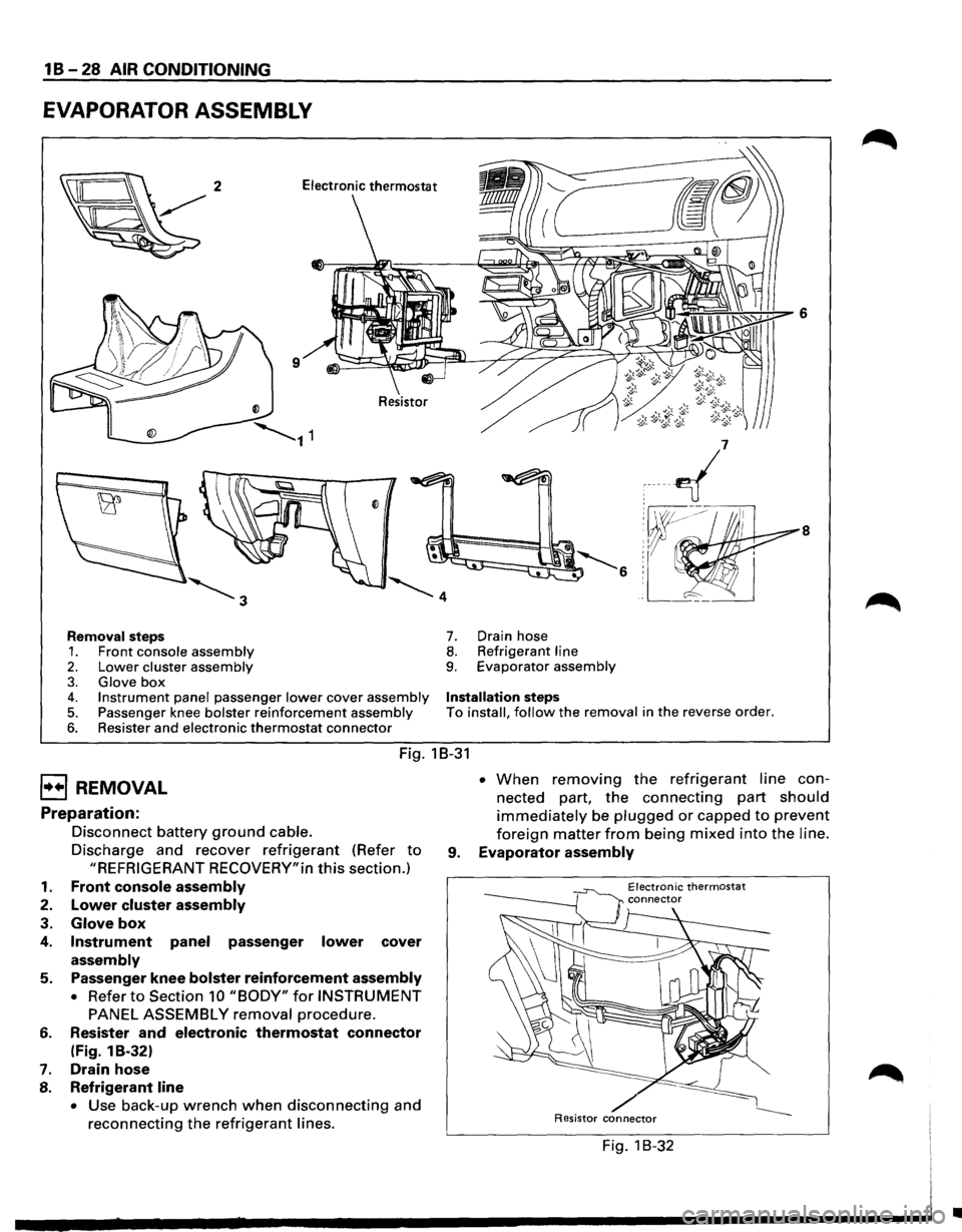
EVAPORATOR ASSEMBLY
8
Removal steps 7. Drain hose
1. Front console assembly 8. Refrigerant line
2. Lower cluster assembly 9. Evaporator assembly
3. Glove box 4. Instrument panel passenger lower cover assembly Installation steps
5. Passenger knee bolster reinforcement assembly To install, follow the removal in the reverse order.
6. Resister and electronic thermostat connector
Fig. 18-31
EJ REMOVAL
Preparation:
1.
2.
3.
4.
5.
6.
7.
8.
Disconnect battery ground cable.
Discharge and recover refrigerant (Refer to
"REFRIGERANT RECOVERY"in this section.)
Front console assembly
Lower cluster assembly
Glove box
Instrument panel passenger lower cover
assembly
Passenger knee bolster reinforcement assembly
• Refer to Section 10 "BODY" for INSTRUMENT
PANEL ASSEMBLY removal procedure.
Resister
and electronic thermostat connector
(Fig. 1 B-32)
Drain hose
Refrigerant line
• Use back-up wrench when disconnecting and
reconnecting the refrigerant lines. •
When removing the refrigerant line con
nected part,
the connecting part should
immediately be plugged or capped to prevent
foreign matter from being mixed into the line.
9. Evaporator assembly
Electronic thermostat
/ Resistor connector
Fig. 1 B-32
•
Page 329 of 1928
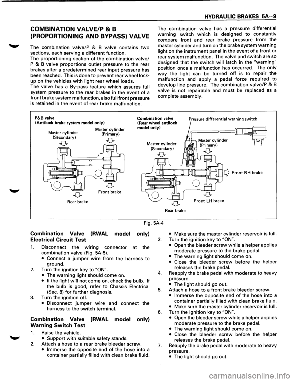
COMBINATION VALVE/P & B
(PROPORTIONING AND BYPASS) VALVE
The combination valve/P & B valve contains two
sections, each serving a different function.
The proportioning section
of the combination valve/
P & B valve proportions outlet pressure to the rear
brakes after a predetermined rear
input pressure has
been reached. This is done to prevent rear
wheel lock
up on the vehicles with light rear wheel loads.
The valve has a By-pass feature which assures full
system pressure to the rear brakes in the event of a
front brake system malfunction, also full front pressure
is retained in the event
of rear brake malfunction.
HYDRAULIC BRAKES 5A 9
The combination valve has a pressure differential
warning switch which is designed to constantly
compare front and rear brake pressure
from the
master
cylinder and turn on the brake system warning
light on the instrument panel in the event of a front or
rear system malfunction. The valve and switch are so
designed that the switch
will latch in the "warning"
position once a malfunction has occurred. The only
way the light can be turned off is to repair the
malfunction and
apply a pedal force required to
develop line pressure. The combination valve/P & B
valve is not repairable and must be replaced as a
complete assembly.
P&B valve
(Antilock brake system model only)
Master cylinder (Primary)
Combination valve (Rear wheel antilock model only)
Pressure differential warning switch
Master
cylinder (Secondary)
..(> ..(> Master cylinder (Secondary) Master
cylinder
(Primary)
..(> ..(>
Front brake
Rear brake
Combination Valve
Electrical Circuit Test (RWAL
model
Fig. 5A-4
only)
1.
2.
3.
Disconnect the wmng connector at the
combination
valve (Fig. 5A-5).
• Connect a jumper wire from the harness to
ground.
Turn the ignition key to
"ON".
•
The warning light should come on.
• If the light will not come on, check the bulb. If
the bulb is good, refer to Chassis Electrical
(Sec.
8) for further diagnosis.
Turn the ignition off.
• Disconnect jumper wire and connect the
harness to the switch
terminal.
Combination Valve (RWAL model only)
Warning
Switch Test
1. Raise the vehicle.
• Support
with suitable safety stands.
2. Attach a hose to a rear brake bleeder screw.
• Immerse the opposite end of the hose into a
container
partially filled with clean brake fluid.
3.
4.
5.
6.
7.
¢ Front RH brake
Front LH brake
Rear brake
• Make sure the master cylinder reservoir is full.
Turn the ignition key to "ON".
• Open
the bleeder screw while a helper applies
moderate pressure to the brake pedal.
•
The warning light should come on.
• Close the bleeder screw before the helper
releases
the brake pedal.
Reapply the brake pedal with moderate to heavy
pressure.
• The light should go out.
Attach a hose
to a front brake bleeder screw.
• Immerse the opposite end of the hose into a
container
partially filled with clean brake fluid.
• Make sure the master cylinder reservoir is full.
Turn the ignition key to "ON".
• Open
the bleeder screw while a helper applies
moderate pressure to the brake pedal.
•
The warning light should come on.
• Close the bleeder screw before the helper
releases
the brake pedal.
Reapply
the brake pedal with moderate to heavy
pressure.
• The light should go out.
Page 334 of 1928
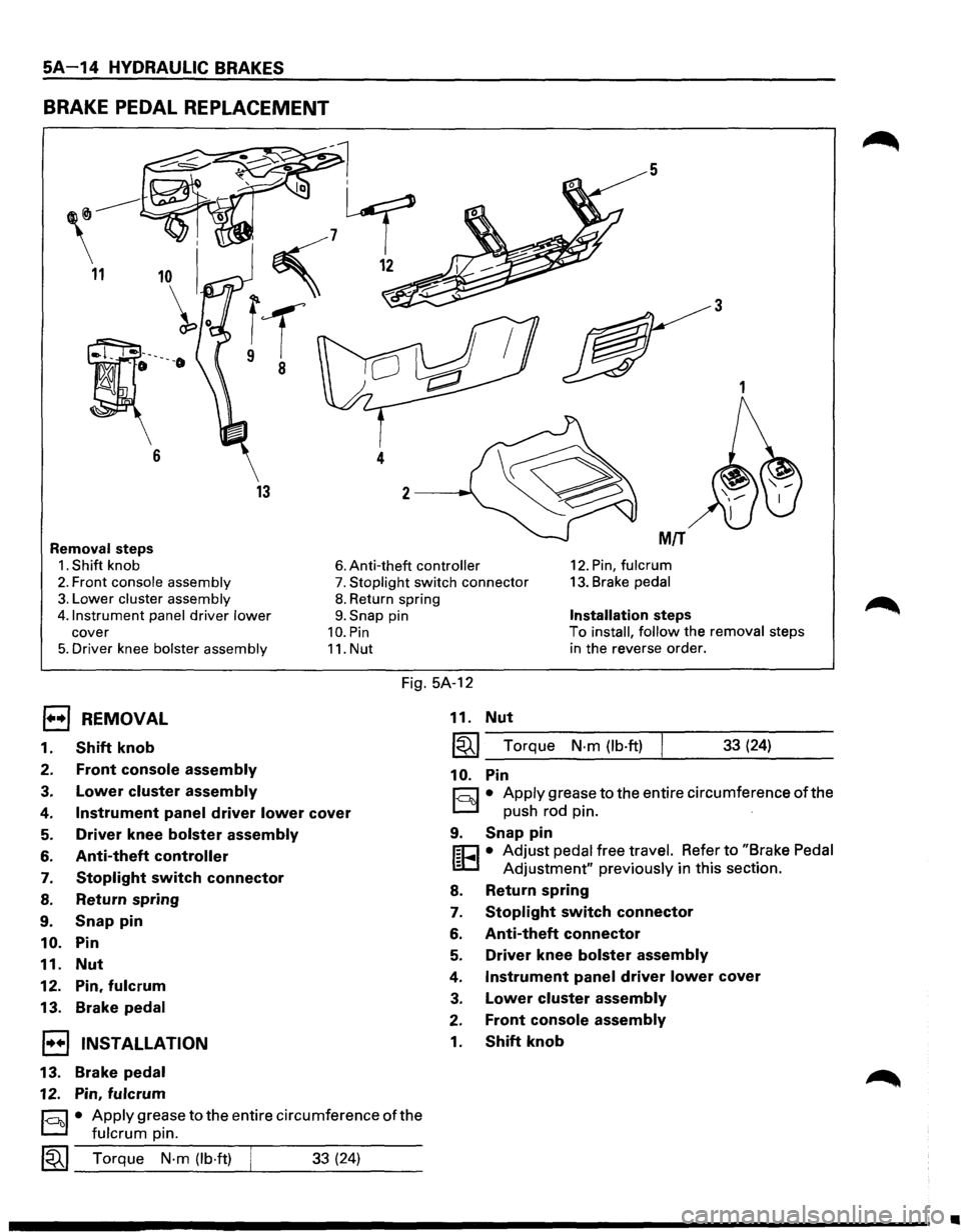
5A-14 HYDRAULIC BRAKES
BRAKE PEDAL REPLACEMENT
5
3
1
13
Removal steps MIT
1. Shift knob 6. Anti-theft controller 12. Pin, fulcrum
2. Front console assembly 7. Stoplight switch connector 13. Brake pedal
3. Lower cluster assembly
4.1nstrument panel
driver lower
cover
5. Driver knee bolster assembly
8. Return spring
9. Snap pin
10. Pin
11. Nut
Installation steps
To install, follow the removal steps
in the reverse order.
Fig. 5A-12
EJ REMOVAL
1. Shift knob
2. Front console assembly
3. Lower cluster assembly
4. Instrument panel driver lower cover
5. Driver knee bolster assembly
6. Anti-theft controller
7. Stoplight switch connector
8. Return spring
9. Snap pin
10. Pin
11.
Nut
12. Pin, fulcrum
13. Brake pedal
1•+1 INSTALLATION
13.
Brake pedal
12. Pin, fulcrum
§)• Apply grease to the entire circumference of the
fulcrum pin.
~~~ Torque N·m (lb·ft) ___ __._ ___ _ 33 (24)
11. Nut
~~~--T-o-rq_u_e __ N-.m--(-lb-.ft-)-.-----3-3-(-24_) ____ _
10. Pin
r:::;:] • Apply grease to the entire circumference of the
D push rod pin. ·
9. Snap pin
f;C1 • Adjust pedal free travel. Refer to "Brake Pedal
lED Adjustment" previously in this section.
8. Return spring
7. Stoplight switch connector
6. Anti-theft connector
5. Driver knee bolster assembly
4. Instrument panel driver lower cover
3. Lower cluster assembly
2. Front console assembly
1. Shift knob
•