fuel pump ISUZU TROOPER 1995 Repair Manual
[x] Cancel search | Manufacturer: ISUZU, Model Year: 1995, Model line: TROOPER, Model: ISUZU TROOPER 1995Pages: 1928
Page 815 of 1928
FUEL INJECTORS
The multipart fuel injection injector assembly is a
solenoid-operated device, controlled
by the Engine
Control Module (ECM), that meters pressurized fuel to
a single engine cylinder.
The
ECM energizes the low impedance (2.0 ohms) for
DOHC or High impedance (12.2 ohms) for SOHC
solenoid to a normally closed ball valve. This allows
fuel
to flow into the top of the injector, past the ball
valve, and through a recessed
flow director plate at the
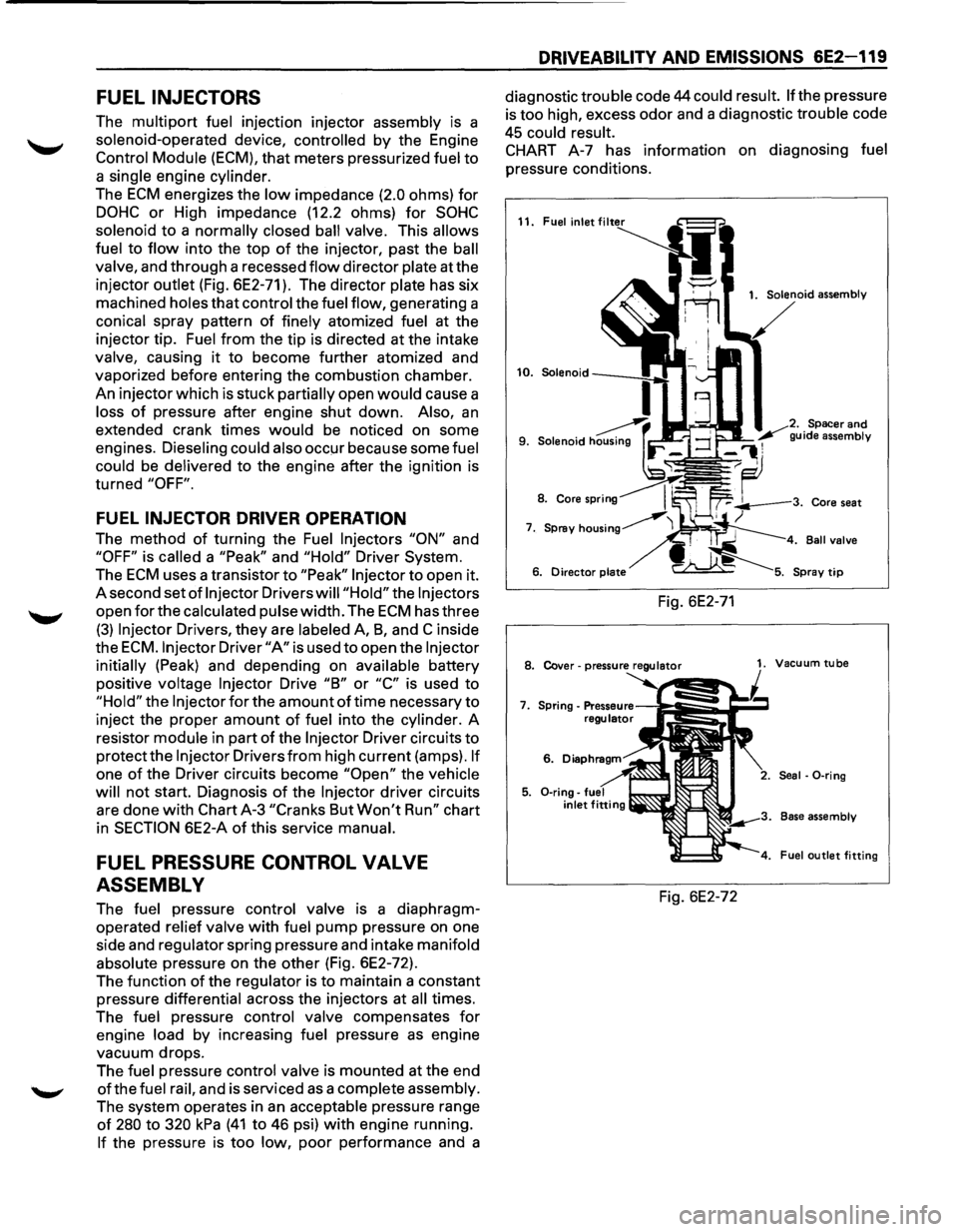
injector outlet (Fig. 6E2-71). The director plate has six
machined holes
that control the fuel flow, generating a
conical spray pattern
of finely atomized fuel at the
injector tip. Fuel
from the tip is directed at the intake
valve, causing
it to become further atomized and
vaporized before entering the combustion chamber.
An injector which is stuck partially open
would cause a
loss
of pressure after engine shut down. Also, an
extended crank times would be noticed on some
engines. Dieseling could also
occ!Jr because some fuel
could be delivered
to the engine after the ignition is
turned
"OFF".
FUEL INJECTOR DRIVER OPERATION
The method of turning the Fuel Injectors "ON" and
"OFF" is called a "Peak" and "Hold" Driver System.
The
ECM uses a transistor to "Peak" Injector to open it.
A second set
of Injector Drivers will "Hold" the Injectors
open for the calculated pulse width. The ECM has three
(3) Injector Drivers, they are labeled A, 8, and C inside
the
ECM. Injector Driver "A" is used to open the Injector
initially (Peak) and depending on available battery
positive voltage
Injector Drive "8" or "C" is used to
"Hold" the Injector for the amount of time necessary to
inject the proper amount of fuel into the cylinder. A
resistor module in part
of the Injector Driver circuits to
protect the Injector Drivers from high current (amps). If
one of the Driver circuits become "Open" the vehicle
will
not start. Diagnosis of the Injector driver circuits
are done
with Chart A-3 "Cranks But Won't Run" chart
in
SECTION 6E2-A of this service manual.
FUEL PRESSURE CONTROL VALVE
ASSEMBLY
The fuel pressure control valve is a diaphragm
operated relief valve
with fuel pump pressure on one
side and regulator spring pressure and intake manifold
absolute pressure on the other (Fig. 6E2-72).
The function
of the regulator is to maintain a constant
pressure differential across the injectors at all times.
The fuel pressure control valve compensates
for
engine load by increasing fuel pressure as engine
vacuum drops.
The fuel pressure control valve is mounted at the end
ofthe fuel rail, and is serviced as a complete assembly.
The system operates in
an acceptable pressure range
of 280 to 320 kPa (41 to 46 psi) with engine running.
If the pressure is too low, poor performance and a
DRIVEABILITV AND EMISSIONS 6E2-119
diagnostic trouble code 44 could result. If the pressure
is too high, excess odor and a diagnostic trouble code
45 could result.
CHART A-7 has information on diagnosing fuel
pressure conditions.
11. Fuel inlet
Fig. 6E2-71
1. Solenoid assembly
Spacer
and
guide assembly
. Ball valve
8. Cover-pressure regulator 1. Vacuum tube
7.
6.
Seal · 0-ring
Base assembly
Fuel
outlet fitting
Fig. 6E2-72
Page 817 of 1928
Throttle Position (TP) Sensor
The Throttle Position (TP) Sensor is mounted on the
side
of the throttle body opposite the throttle lever
assembly.
Its function is to sense the current throttle
body position and relay that information to the ECM.
Knowledge ofTP is needed by the ECM to generate the
proper injector pulse width.
If the TP sensor senses a
Wide
Open Throttle, a voltage signal indicating this
condition is transmitted to the
ECM. The ECM will
widen the injector pulse, or increase the repetition rate,
permitting increased fuel
flow to each for the six fuel
injectors located in the fuel fail. As the throttle shaft
rotates in response to
movement of the accelerator
pedal (opening
or closing of the throttle body), the
throttle shaft transmits throttle
movement to the TP
sensor. A potentiometer (variable resistor) within the
TP sensor assembly creates a voltage that varies in
response to
TP. By applying a reference voltage (+5
VDC) to the TP sensor input, a varying voltage
(reflecting
TP) is available at the TP sensor output. The
voltage
output from the TP sensor is sent to the ECM
for use in determining current TP.
For further information ofTP sensor, refer to "ECM and
Sensors", Section
"6E2-C1 ". The TP sensor is an auto
zeroing type and cannot
be adjusted.
DRIVEABILITY AND EMISSIONS 6E2-121
INDUCTION AIR CONTROL PLATE
SYSTEM (DOHC) (Fig. 6E2-74)
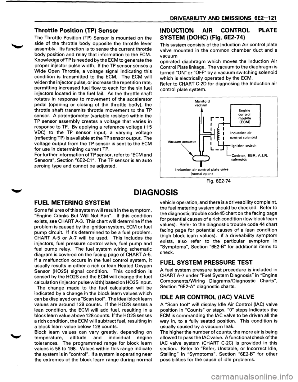
This system consists of the Induction Air control plate
valve mounted in the common chamber
duct and a
vacuum operated diaphragm
which moves the Induction Air
Control Plate linkage. The vacuum to the diaphragm is
turned
"ON" or "OFF" by a vacuum switching solenoid
which is electrically operated by the
ECM.
Refer to CHART C-20 for diagnosing the Induction air
control plate system.
Manifold vaccum
1
Vacuum actuator
Induction air control plate valve
(noma! open)
Fig. 6E2-74
Engine control module (ECM)
Ignition switch
Canister, EGR, A.I.R. solenoids
DIAGNOSIS
FUEL METERING SYSTEM
Some failures of this system will result in the symptom,
"Engine Cranks But Will Not Run". If this condition
exists, see CHART A-3. This chart will determine
if the
problem is caused by the ignition system,
ECM or fuel
pump circuit.
If it's determined to be a fuel problem.
CHART A-5
or A-7 will be used. This includes the
injectors, fuel pressure control valve, fuel
pump and
fuel pump relay. The fuel system
wiring schematic
diagram is covered on the facing page
of CHART A-5.
If a malfunction occurs in the fuel control system, it
usually results in either a rich or lean Heated Oxygen
Sensor (H02S) signal condition. This condition is
sensed by the
H02S and the ECM will change the fuel
calculation (injector pulse width) based on
H02S input.
The change made to the fuel calculation will be
indicated
by a change in the block learn values which
can be displayed on a
"Scan tool". The ideal block learn
values are around 128 counts.
If the H02S senses a
lean condition, the
ECM will add fuel, resulting in a
block learn value above 128 counts.
If the H02S senses
a rich condition, the
ECM will subtract fuel, resulting in
a block learn value below 128 counts.
Block learn values can vary greatly, depending on
temperature, altitude and individual engine
tolerances. The programmed range for block learn
values is
58 to 198. Values within this range indicate
the system is in
"control". If a system is operating near
the extremes
of the block learn range during normal vehicle
operation, and there is a driveability complaint,
the fuel metering system should be checked. Refer to
the diagnostic trouble code
45 chart on the facing page
for potential causes of a rich condition (low block learn
values). Refer to the diagnostic trouble code 44 chart
facing page
for potential causes of a lean condition
(high block learn values).
If a driveability symptom
exists, also refer to the particular symptom in
"Symptoms", Section "6E2-B" for additional items to
check.
FUEL SYSTEM PRESSURE TEST
A fuel system pressure test procedure is included in
CHART A-7 under
"Fuel System Diagnosis" in "Engine
Components/Wiring Diagrams/Diagnostic
Charts",
Section "6E2-A" diagnostic charts.
IDLE AIR CONTROL (lAC) VALVE
A "Scan tool" will display Idle Air Control (lAC) valve
position in
"Counts" or steps. "0" steps indicates the
ECM is commanding the lAC valve to be driven all the
way in, to a fully seated position. This condition is
usually caused by a vacuum leak.
The higher the number
of counts, the more air is being
allowed to pass the
lAC valve. A functional check of the
lAC valve system (CHART C-2C) is provided in this
section. Refer to
"Refer, Unstable, or Incorrect Idle,
Stalling"
in "Symptoms", Section "6E2-B" for other
possibilities
for the cause of idle problems.
Page 818 of 1928
6E2-122 DRIVEABILITV AND EMISSIONS
INDUCTION AIR CONTROL PLATE
SYSTEM
Refer to CHART C-2D to diagnose the Induction air
control plate system.
ON-VEHICLE SERVICE
FUEL PUMP RELAY
The fuel pump relay is mounted in the engine
compartment.
Other than checking for loose
connectors, the only service possible is replacement.
MUL TIPORT FUEL INJECTION
COMPONENTS
WCAUTION:
VI • To reduce the risk of fire and personal injury, it
is necessary to relieve the fuel system pressure
before servicing
fuel system components.
• After relieving system pressure, a small
amount of fuel may be released when servicing
fuel lines or connections. In order to reduce the
chance
of personal injury, cover fuel line
fittings with a shop towel before disconnecting,
to catch any
fuel that may leak out. Place the
towel in an approved container when
disconnect is completed.
Fuel Pressure Relief Procedure
1. Remove fuel cap.
2. Remove fuel pump relay from underhood relay
box.
3. Start engine and allow to stall.
4. Crank engine for additional 30 seconds.
5. Remove negative battery cable.
FUEL RAIL ASSEMBL V
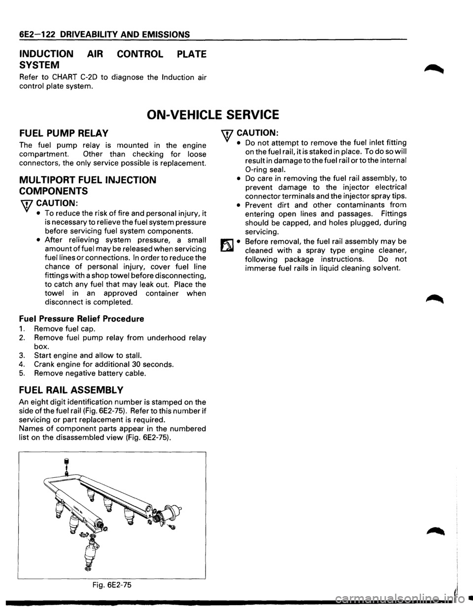
An eight digit identification number is stamped on the
side
ofthe fuel rail (Fig. 6E2-75). Refer to this number if
servicing or part replacement is required.
Names
of component parts appear in the numbered
list on the disassembled view (Fig. 6E2-75).
'fCAUTION:
• Do not attempt to remove the fuel inlet fitting
on the
fuel rail, it is staked in place. To do so will
result
in damage to the fuel rail or to the internal
0-ring seal.
•
Do care in removing the fuel rail assembly, to
prevent damage to the injector
electrical
connector terminals and the injector spray tips.
• Prevent dirt and other contaminants from
entering open lines and passages. Fittings
should be capped, and holes plugged, during
servicing.
Before
removal, the fuel rail assembly may be
cleaned with a spray type engine cleaner,
following
package instructions. Do not
immerse fuel rails in liquid cleaning solvent.
Fig. 6E2-75
I'
---------------------'
•
Page 824 of 1928
6E2-128 DRIVEABILITY AND EMISSIONS
CHART C-2A
INJECTOR BALANCE TEST
The injector balance tester is a tool used to turn the injector on for a precise amount of time, thus spraying a
measured
amount of fuel into the manifold. This causes a drop in fuel rail pressure that we can record and
compare between each injector.
All injectors should have the same amount of pressure drop (± 10 kPa). Any
injector with a pressure drop that is 10 kPa (or more) greater or less than the average drop of the other injectors
should be considered faulty and replaced.
NOTE: It will be necessary to remove the intake plenum to perform this procedure. Refer to intake plenum
remove procedure in this section. It will also be necessary to install the Intake Manifold Diagnostic Plate J
39185 to enable the engine to be run with the plenum removed. Refer to Chart A-8 in Section "6E2-A" of
this service manual.
STEP 1
Engine "cool down" period (10 minutes) is necessary to avoid irregular readings due to "Hot Soak" fuel boiling.
With ignition "OFF" connect fuel gauge J 347301 or equivalent to fuel pressure tap. Wrap a shop towel around
fitting
while connecting gage to avoid fuel spillage. Refer to Chart A-7 in Section 6E2-A, Page 1 of 3.
Disconnect harness connectors at all injectors, and connect injector tester J 34730-3, or equivalent, to one injector.
Follow manufacturers instructions for use of adaptor harness. Ignition must be "OFF" at least 10 seconds to
complete engine control module shutdown cycle. Fuel pump should run about 2 seconds after ignition is turned
"ON". At this point, insert clear tubing attached to vent valve into a operation. Repeat this step until all air is bled
from gauge.
STEP 2
Turn ignition "OFF" for 10 seconds and then "ON" again to get fuel pressure to its maximum. Record this initial
pressure reading. Energize tester one time and note pressure drop at its lowest point (Disregard any slight
pressure increase after drop hits low point). By subtracting this second pressure reading from the initial pressure, ~
we have the actual amount of injector pressure drop.
STEP 3
Repeat step 2 on each injector and compare the amount of drop. Usually, good injectors will have virtually the
same drop. Retest any injector
that has a pressure difference of 10 kPa, either more or less than the average of the
other injectors on the engine.
Replace any injector that also fails the retest. If the pressure drop of all injectors is
within 10 kPa of this average, the injectors appear to be following properly.
Reconnect them and review "Symptoms", Section "6E3-B".
NOTE: The entire test should NOT be repeated more than once without running the engine to prevent flooding.
(This includes any retest on faulty injectors). To run the engine with the intake plenum removed use the
Intake Manifold Diagnostic Plate.
•
Page 831 of 1928
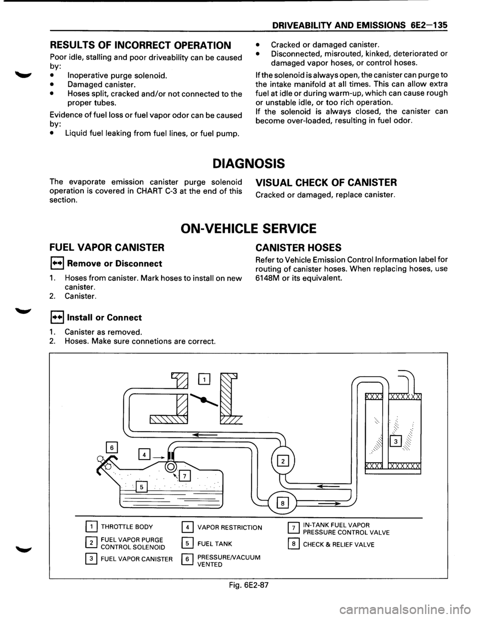
RESULTS OF INCORRECT OPERATION
Poor idle, stalling and poor driveability can be caused
by:
• Inoperative purge solenoid.
•
Damaged canister.
• Hoses split, cracked and/or not connected to the
proper tubes.
Evidence
of fuel loss or fuel vapor odor can be caused
by:
• Liquid fuel leaking from fuel lines, or fuel pump.
DRIVEABILITY AND EMISSIONS 6E2-135
• Cracked or damaged canister.
• Disconnected, misrouted, kinked, deteriorated or
damaged vapor hoses,
or control hoses.
If the solenoid is always open, the canister can purge to
the intake manifold at all times. This can allow extra
fuel at idle or during warm-up, which can cause rough
or unstable idle, or too rich operation.
If the solenoid is always closed, the canister can
become over-loaded,
resulting in fuel odor.
DIAGNOSIS
The evaporate em1ss1on canister purge solenoid
operation is covered in CHART C-3 at the end of this
section. VISUAL CHECK OF CANISTER
Cracked or damaged, replace canister.
FUEL VAPOR CANISTER
1••1 Remove or Disconnect
ON-VEHICLE SERVICE
CANISTER HOSES
1. Hoses from canister. Mark hoses to install on new
canister. Refer
to Vehicle Emission Control
Information label for
routing of canister hoses. When replacing hoses, use
6148M
or its equivalent.
2. Canister.
l••llnstall or Connect
1. Canister as removed.
2. Hoses. Make sure connetions are correct.
[2] THROTTLE BODY
r:l FUEL VAPOR PURGE ~ CONTROL SOLENOID
0 FUEL VAPOR CANISTER
0 VAPOR RESTRICTION
0 FUEL TANK
r.;;'l PRESSURENACUUM L....J VENTED
Fig. 6E2-87
r-:;-1 IN-TANK FUEL VAPOR ~ PRESSURE CONTROL VALVE
0 CHECK & RELIEF VALVE
Page 862 of 1928
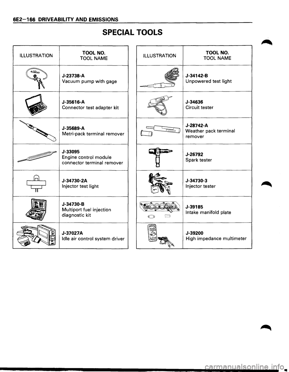
6E2-166 DRIVEABILITY AND EMISSIONS
SPECIAL TOOLS
ILLUSTRATION TOOL NO.
TOOL NAME ILLUSTRATION
~
J-23738-A
Vacuum pump with gage
~
J-35616-A
Connector test adapter kit
'
J-35689-A
Metri-pack terminal remover
~
J-33095
Engine control module
connector terminal remover
$
J-34730-2A
Injector test light
•
J-34730-B
Multipart fuel injection
diagnostic kit
~~~ J-37027A
~~~
Idle air control system driver
TOOL NO.
TOOL NAME
J-34142-B
Unpowered test light
J-34636
Circuit tester
J-28742-A
Weather pack terminal
remover
J-26792
Spark tester
J-34730-3
Injector tester
J-39185
Intake manifold plate
J-39200
High impedance multimeter
..
Page 874 of 1928
7A-2 AUTOMATIC TRANSMISSION (4L30-E)
Valve Body Assembly (Adapter Case) ....... 7A-168 Third Clutch and Sprag Unit ....................... 7A-195
Transmission Control
Module (TCM) ......... 7A-169 Third Clutch .................................................. 7A-196
Speed Sensor (Extension Housing) ............ 7A-169 Sprag
Unit ....................................................
7A-198
Transmission
Oil Temperature Sensor Second
Clutch .............................................. 7A-199
(Adapter Case) ..........................................
7A-170 3-4 Accumulator Piston ............................... 7A-200
Front Oil Seal (Converter Housing) ............ 7A-170 Reverse Clutch Piston and Center
Rear
Oil Seal (Extension Housing) ............. 7A-171 Support ..................................................... 7 A-202
Unit Repair ........................................................ 7A-173 Overrun Clutch and Turbine Shaft ............. 7A-204
Transmission (4L30-E) ................................. 7A-173 Main Data and Specifications ......................... 7 A-207
Converter Housing and Oil Pump General
Specifications ................................. 7 A-207
Assembly .................................................. 7 A-189 Torque
Specifications .................................. 7A-208
Oil
Pump ....................................................... 7A-190 Special Tools .................................................... 7A-211
Main Case Valve Body ................................. 7A-191 4L30-E Parts List.. ............................................. 7A-213
Adapter Case Valve Body ............................ 7A-193 Hydraulic
Circuit Diagram .......... End of This Manual
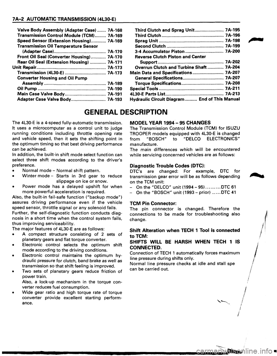
GENERAL DESCRIPTION
The 4L30-E is a 4-speed fully-automatic transmission.
It uses a microcomputer as a control unit to judge
running conditions
including throttle opening rate
and vehicle speed, then
it sets the shifting point in
the
optimum timing so that best driving performance
can be achieved.
In addition, the built-in shift mode select function can
select three shift modes according to the driver's
preference.
• Normal mode-Normal shift pattern.
• Winter mode-Starts in 3rd gear to reduce
slippage on ice
or snow.
• Power mode has a delayed upshift for when
more powerful acceleration is required.
Also, the built-in fail-safe
function ("backup mode")
assures driving performance even if the vehicle
speed sensor,
throttle signal or any solenoid fails.
Further, the self-diagnostic
function conducts diag
nosis in a short time when the control system fails,
thus improving serviceability.
The major features of 4L30-E are as follows:
• A compact structure consisting of 2 sets of
planetary gears and flat torque converter.
• Electronic control selects the optimum shift
mode according
to the driving conditions.
• Electronic control maintains the optimum hy
draulic pressure for clutch, band brake as well as
transmission so that shift feeling is improved.
• Two sets of planetary gears reduce friction of
power train.
Also, a lock-up mechanism in the torque con
verter reduces fuel consumption.
• Wide gear ratio and high torque rate of torque
converter provide
excellent starting perform
ance.
MODEL YEAR 1994-95 CHANGES
The Transmission Control Module (TCM) for ISUZU
TROOPER
models equipped with 4L30-E is changed
from "BOSCH" to "DELCO ELECTRONICS"
manufacture.
The main differences
which will be encountered
while servicing concerned vehicles are as follows:
Diagnostic Trouble Codes (DTC):
DTC's are changed: For example, DTC for
transmission gear error will be as follows depending
on the TCM unit:
-
On the "DELCO" unit (1994-95) ......... DTC 61
-On the "BOSCH" unit (1993-prior) ..... DTC 41
TCM Pin Connector:
The pin connector is changed. Therefore the
connections
to be made for troubleshooting also
change.
Shift Alteration when TECH 1 Tool is connected
toTCM:
SHIFTS WILL BE HARSH WHEN TECH 1 IS
CONNECTED.
Connection of TECH 1 automatically forces maximum
line pressure during shifts only.
Normal line pressure checks at idle and stall spe
can be carried out.
/
/
I J I
/
l
•
Page 1211 of 1928
CHASSIS ELECTRICAL 8-21
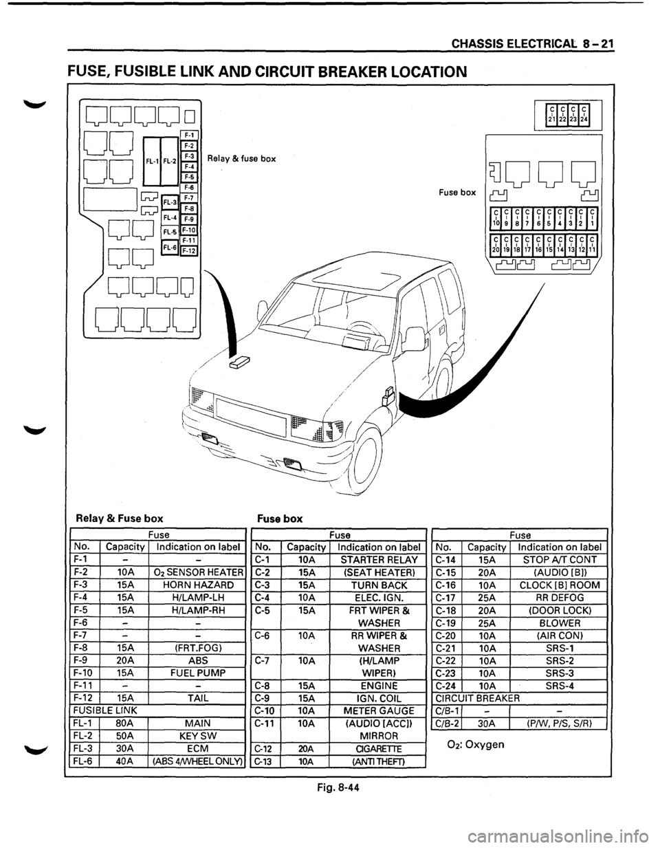
FUSE, FUSIBLE LINK AND CIRCUIT BREAKER LOCATION
ooooo 112~12~1~1~1
00 E
EEr 00 ~
Relay & fuse box
SJOOO 7-6
I lw ;;::;~ Fuse box ~ ~
1l1~~ ~lff~UIH~Inll
w~ F-a FL-4 ~
00 FL·S~ r---, F-11 'l2~J1~ 1~1&11~11~1,\l~31hl1~1
0
0
FL-6 'F-i2
I' ~
\a~ a~;
0000
0000
I ~
l/
~
j
~/~/ e:;?' v II I / / .I / /
('-/ .
~~
-~-~;,a~ ~~ --.:_
~~~~ -
Relay & Fuse box Fuse box
Fuse
Fuse Fuse
No. Capacity Indication on label No. Capacity Indication on label No. Capacity Indication on label
F-1 --C-1 10A STARTER RELAY
C-14 15A STOP A!f CONT
F-2 10A 02 SENSOR HEATER C-2 15A (SEAT HEATER)
C-15 20A (AUDIO [8))
F-3
15A HORN HAZARD C-3 15A
TURN BACK C-16 10A CLOCK (8] ROOM
F-4
15A H/LAMP-LH C-4 10A ELEC.IGN. C-17 25A RR DEFOG
F-5
15A H/LAMP-RH C-5
15A FRTWIPER & C-18 20A (DOOR LOCK)
F-6 --WASHER C-19
25A BLOWER
F-7
- -C-6 10A RRWIPER & C-20 10A (AIR
CON)
F-8
15A (FRT.FOG) WASHER C-21 10A SRS-1
F-9 20A ABS C-7 10A (H/LAMP C-22 10A SRS-2
F-10
15A FUEL PUMP WIPER) C-23 lOA SRS-3
F-11 -
-C-8 15A ENGINE C-24 10A SRS-4
F-12
15A TAIL C-9 15A IGN. COIL CIRCUIT BREAKER
FUSIBLE
LINK
C-10 10A METER GAUGE
C/8-1 --FL-1 80A MAIN C-11 10A
(AUDIO IACC])
C/8-2 30A (P/W, P/S, S/R)
FL-2 50 A KEYSW MIRROR
FL-3 30A ECM C-12 20A CIGARETTE 02: Oxygen
FL-6 40A (ASS 4/WHEEL ONLY) C-13 10A (ANTI THEFT)
Fig. 8-44
Page 1212 of 1928
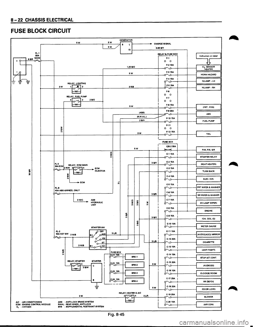
8-22 CHASSIS ELECTRICAL
FUSE BLOCK CIRCUIT
GENERATOR -------------------~s~w~------------~~s~w~--~~~~ r- / B L 1------CHARGE SIGNAL &W _/
FL-1 80A .-----, B 11.'1 MAIN
+ Lt--
l£h
~----/ IG~----------~O~.$~B/V~-----------,
3W REL~HT1NG 1J ---'"~L 3
RELA~PUMP 4 1...---. 12 2 B/0
1.25 B/0
SW
3RJ8
5W
~~~·~ F-1 0 0 F-2 10A
I F-315A
F-8
0 0 F-7 0 0 F-81SA
F-920A
9;nlaool
I
Oz SENSOR HEATER
HORN HAZARD
H/LAMP-LH
H/LAMP-RH
(FRT. FOG)
lABS) -I ABS
I ,--------__:<;;:R·.:.:W.::..Acc·L;;:-1 ____ ----Jv F-10 1SA 2 810
I
~ECM RELAY; ECM MAIN ¢~,...,..J>--+2'-'RIW~_::2~1-o.....-<:>-f-·4.:._ __ _. ~J~CTOR
L...-_.ECM
FL-t 40A ABS 4/WHEEL ONLY
"
.... ...
SW
5W
3 8IY
F-11 0 0 F-1215A
~------' FUSE BOX
CIB-2 30A ~.,.;
C-110A :
C-215A
C-31SA
C-410A
I
J
FUEL PUMP
TAIL
P/W, PIS. SIR
STARTER RELAY
(SEAT HEATER)
TURN BACK
ELEC.IGN.
e-s
15A 1 ""'-.0---t-----+----il FRT WIPER & WASHER
"""' -
I 3W/G
C-810A '---f-+----+.:3.:BIR::::..+---¢""''-£>---i-----f-----jl RR WIPER & WASHER
ABS HYORAULIC UNIT
STARTERSW
FL-2 _JJ OFF
~ ...
..:..AKEYSW 3 W/B ay ' o.N". 3UB
~~--~--~,~------~-0 ~~IG~2Y-----------~ o-: ST 3W/B 81 -.,IG1
FUSE BOX
I
I g1~ 1 J'-:::s:R:s-:1 =I RELAY; STARTER
STARTER I r-
L~---'~-j.t
I I 3UB
sw
C-710A
~';::--~--~-'---~~~HI~LA~M~P~W~IP~E~R~l~~ C-81SA ""'-'>--1---...__---i ENGINE
C-111SA I J~======~l IGN. COIL (G)
C-10 10A
C-1110A
k'-1:>----t----t
~==~I
METER GAUGE
""''-£>---f----------1 (AUDIO[ACC)) MIRROR
C-12 20A
::...1310A I
C-141SA -r"\'-1)----f----t
C-15 20A L,-.
CIGARETTE
(ANTITHEFT)
STOP A/T CONT.
(AUDIO[ B))
C-1810A """"-'-.0---f----------t_j CLOCK[B) ROOM
L---+------------------------iB lt~;_ ~=~~~:~:~::~~~: C-17 2SA I
G1820A
RR DEFOG
= sw (DOOR LOCK) RELAY; HEATER &A/C .:._ __________________ .:.:3~W'-'---------------------~2to~.....-4 3UR C-19 2SA ...... BLOWER
A/C : AIR CONDITIONING ECM : ENGINE CONTIIOL MODULE 0, :OXYGEN ABS
:ANTI-LOCK
BRAKE BYBTEM
RWAL: REAR WHEEL ANTI-LOCK BRB : SUPPLEMENTAL RESTRAINT SYSTEM
C-20 10A (AIR CON)
Fig. 8-45
•
Page 1213 of 1928
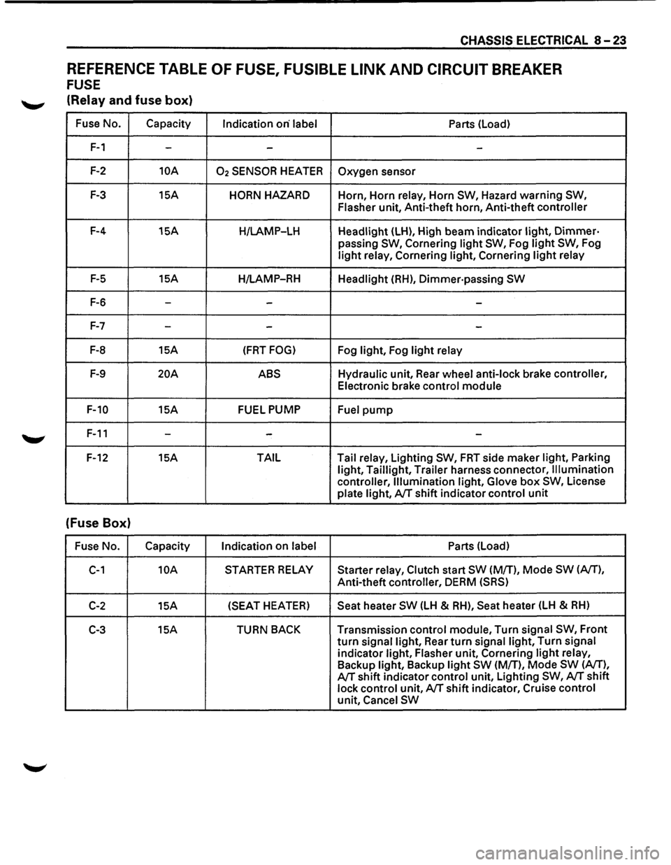
CHASSIS ELECTRICAL 8-23
REFERENCE TABLE OF FUSE, FUSIBLE LINK AND CIRCUIT BREAKER
FUSE
'--"' (Relay and fuse box)
Fuse No. Capacity
Indication on· label Parts (Load)
F-1 --
-
F-2 10A 02 SENSOR HEATER Oxygen sensor
F-3 15A HORN HAZARD Horn, Horn relay, Horn SW, Hazard warning SW,
Flasher
unit, Anti-theft horn, Anti-theft controller
F-4 15A
H/LAMP-LH Headlight (LH), High beam indicator light, Dimmer·
passing SW, Cornering light SW, Fog light SW, Fog
light relay, Cornering light, Cornering light relay
F-5 15A
H/LAMP-RH Headlight (RH), Dimmer·passing SW
F-6 ---
F-7 --
-
F-8 15A (FRT FOG) Fog light, Fog light relay
F-9 20A ABS Hydraulic unit, Rear wheel anti-lock brake controller,
Electronic brake control module
F-10 15A FUEL PUMP
Fuel pump
F-11 ---
F-12 15A TAIL Tail
relay, Lighting SW, FRT side maker light, Parking
light, Taillight, Trailer harness connector, Illumination
controller, Illumination light, Glove
box SW, License
plate light, A/T shift indicator control unit
(Fuse Box)
Fuse No. Capacity
Indication on label Parts (Load)
C-1 10A STARTER RELAY Starter relay, Clutch start SW (M/T), Mode SW (A/T),
Anti-theft controller, DERM (SRS)
C-2 15A (SEAT
HEATER) Seat heater SW (LH & RH), Seat heater (LH & RH)
C-3 15A TURN BACK Transmission control module, Turn signal SW, Front
turn signal light, Rear turn signal light, Turn signal
indicator light, Flasher unit, Cornering light relay,
Backup light, Backup light SW (M/T), Mode SW (A/T),
A/T shift indicator control unit, Lighting SW, A/T shift
lock control unit, A/T shift indicator, Cruise control
unit, Cancel SW