fuel pump ISUZU TROOPER 1995 Repair Manual
[x] Cancel search | Manufacturer: ISUZU, Model Year: 1995, Model line: TROOPER, Model: ISUZU TROOPER 1995Pages: 1928
Page 750 of 1928
6E2-54 DRIVEABILITY AND EMISSIONS
Circuit
description
CHART A-7
(Page 3 of 3)
FUEL SYSTEM PRESSURE TEST
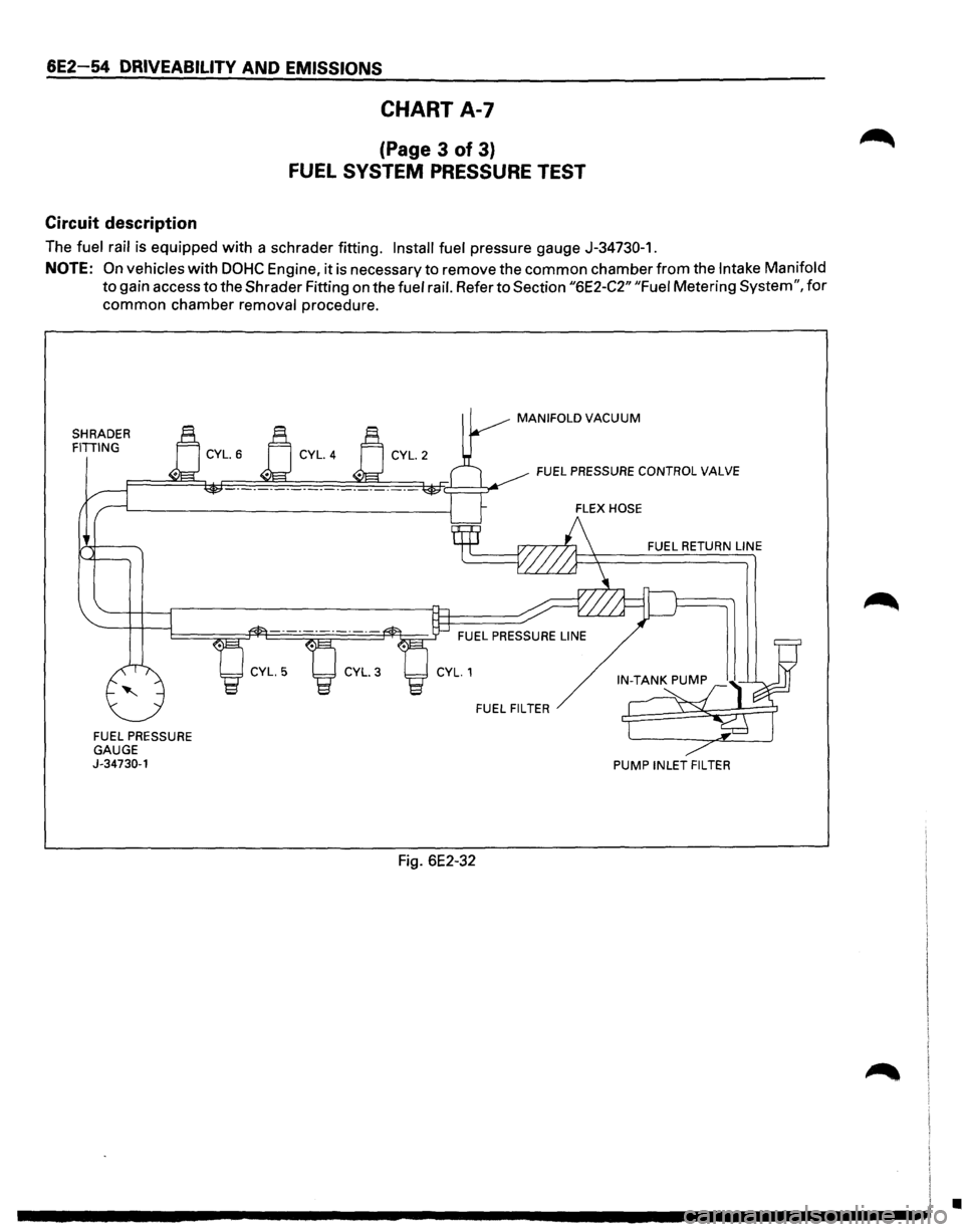
The fuel rail is equipped with a schrader fitting. Install fuel pressure gauge J-34730-1.
NOTE: On vehicles with DOHC Engine, it is necessary to remove the common chamber from the Intake Manifold
to gain access to the Shrader Fitting on the fuel rail. Refer to Section "6E2-C2" "Fuel Metering System", for
common chamber removal procedure.
SHRADER FITIING
FUEL PRESSURE
GAUGE
J-34730-1
Fig. 6E2-32
MANIFOLD VACUUM
FUELPRESSURECONTROLVALVE
FUEL RETURN LINE
FUEL FILTER
PUMP INLET FIL TEA
•
Page 751 of 1928
DRIVEABILITY AND EMISSIONS 6E2-55
CHART A-7
(Page 3 of 3)
FUEL SYSTEM PRESSURE TEST
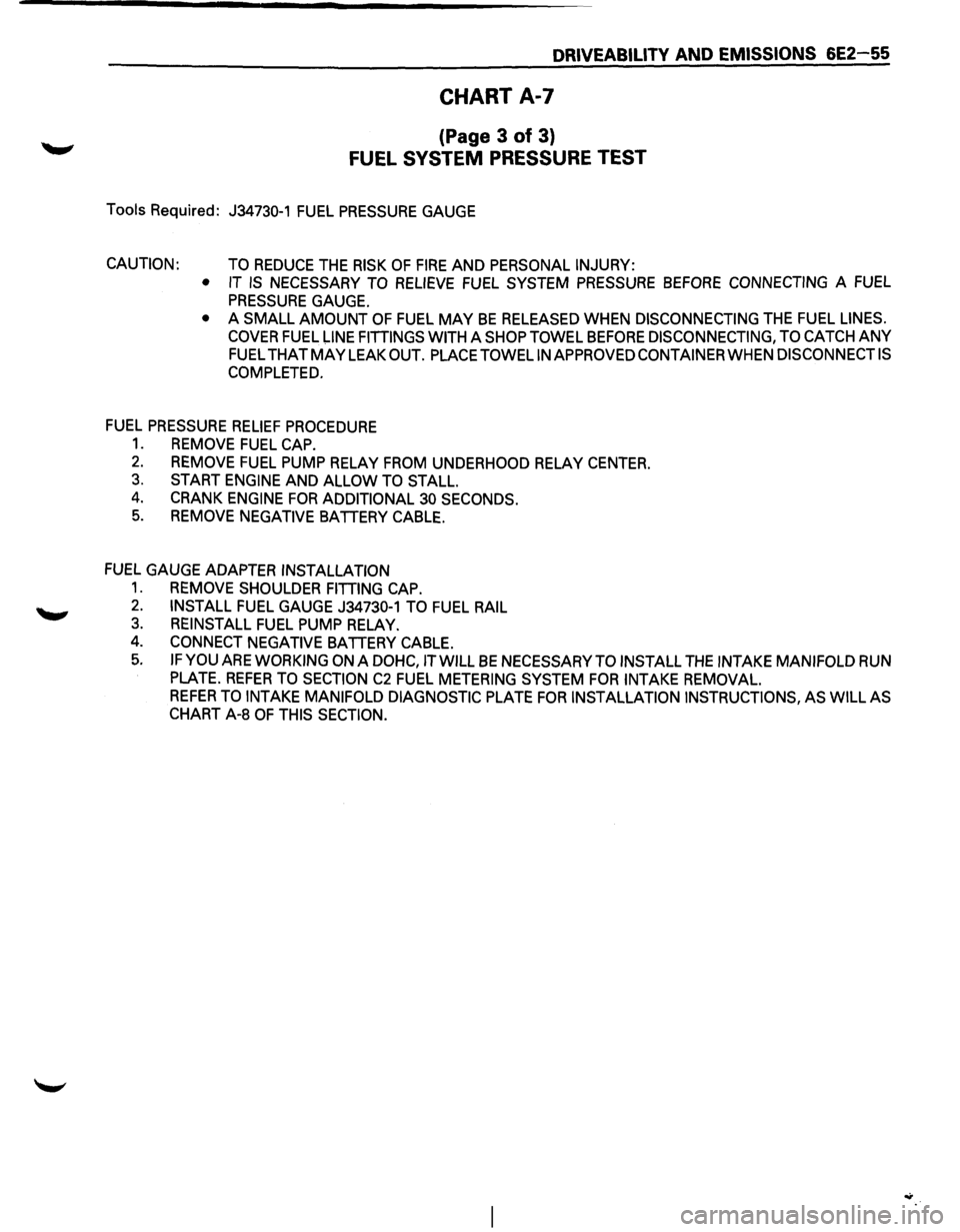
Tools Required: J34730-1 FUEL PRESSURE GAUGE
CAUTION: TO REDUCE THE RISK OF FIRE AND PERSONAL INJURY:
• IT
IS NECESSARY TO RELIEVE FUEL SYSTEM PRESSURE BEFORE CONNECTING A FUEL
PRESSURE GAUGE.
• A SMALL AMOUNT OF FUEL MAY BE RELEASED WHEN DISCONNECTING THE FUEL LINES.
COVER FUEL l-INE FITTINGS WITH A SHOP TOWEL BEFORE DISCONNECTING, TO CATCH ANY
FUEL THATMAYLEAKOUT. PLACETOWELINAPPROVEDCONTAINERWHENDISCONNECTIS
COMPLETED.
FUEL PRESSURE
RELIEF PROCEDURE
1. REMOVE FUEL CAP.
2. REMOVE FUEL PUMP RELAY FROM UNDERHOOD RELAY CENTER.
3. START
ENGINE AND ALLOW TO STALL.
4. CRANK ENGINE FOR ADDITIONAL 30 SECONDS.
5. REMOVE NEGATIVE BATTERY CABLE.
FUEL GAUGE ADAPTER
INSTALLATION
1. REMOVE SHOULDER FITTING CAP.
2. INSTALL FUEL GAUGE J34730-1 TO FUEL RAIL
3. REINSTALL FUEL PUMP RELAY.
4. CONNECT NEGATIVE BATTERY CABLE.
5. IF YOU ARE WORKING ON A DOHC, IT WILL BE NECESSARY TO INSTALL THE INTAKE MANIFOLD RUN
PLATE.
REFER TO SECTION C2 FUEL METERING SYSTEM FOR INTAKE REMOVAL.
REFER TO INTAKE MANIFOLD DIAGNOSTIC PLATE FOR INSTALLATION INSTRUCTIONS, AS WILL AS
CHART A-8 OF THIS SECTION.
Page 753 of 1928
DRIVEABILITY AND EMISSIONS 6E2-57
CHART A-8
INTAKE MANIFOLD DIAGNOSTIC PLATE
(INSTALLATION PROCEDURE)
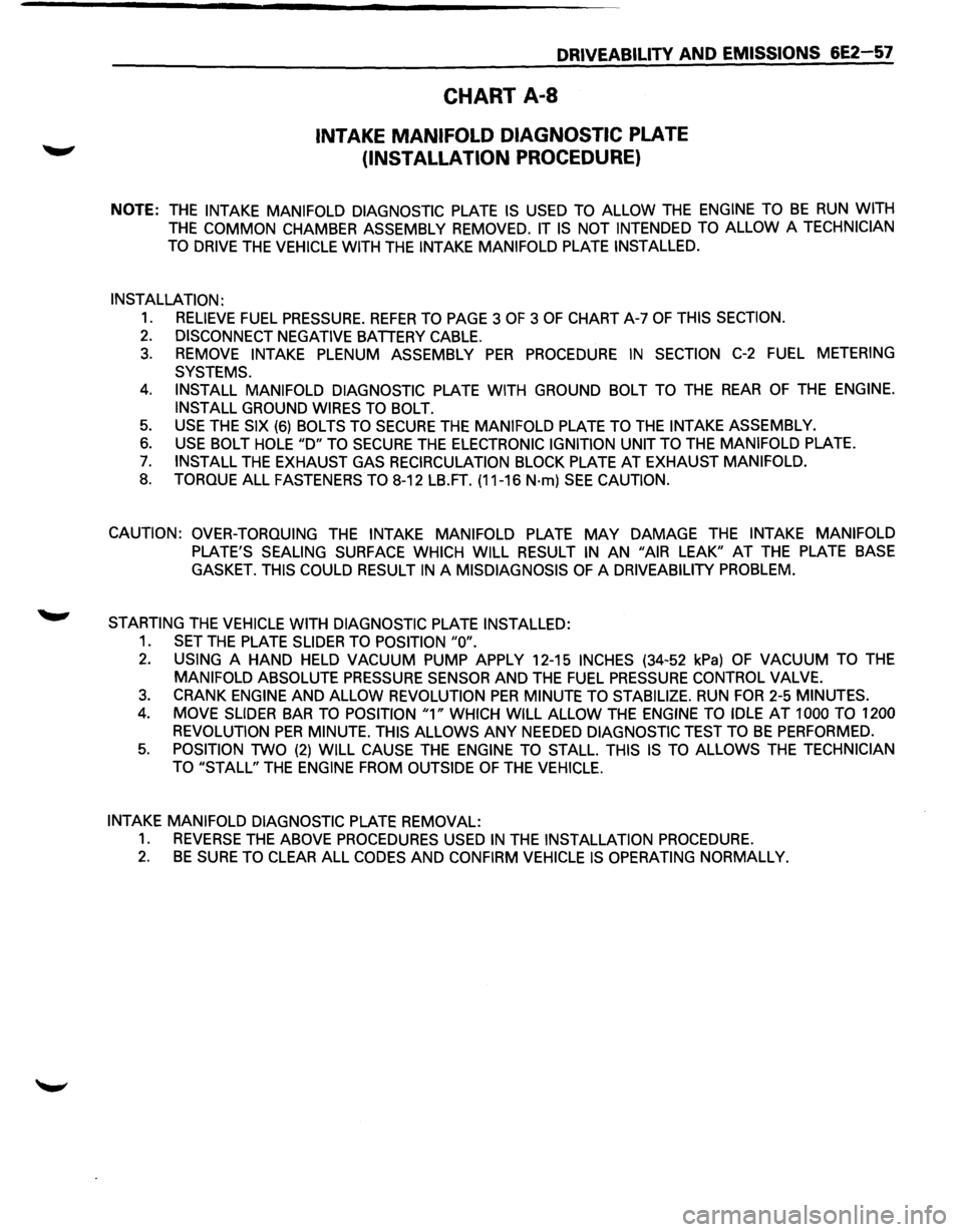
NOTE: THE INTAKE MANIFOLD DIAGNOSTIC PLATE IS USED TO ALLOW THE ENGINE TO BE RUN WITH
THE COMMON CHAMBER ASSEMBLY REMOVED. IT IS NOT INTENDED TO ALLOW A TECHNICIAN
TO
DRIVE THE VEHICLE WITH THE INTAKE MANIFOLD PLATE INSTALLED.
INSTALLATION:
1. RELIEVE FUEL PRESSURE. REFER TO PAGE 3 OF 3 OF CHART A-7 OF THIS SECTION.
2. DISCONNECT NEGATIVE BATTERY CABLE.
3. REMOVE INTAKE PLENUM ASSEMBLY PER PROCEDURE IN SECTION C-2 FUEL METERING
SYSTEMS.
4. INSTALL MANIFOLD DIAGNOSTIC PLATE WITH GROUND BOLT TO THE REAR OF THE ENGINE.
INSTALL
GROUND WIRES TO BOLT.
5. USE THE SIX (6) BOLTS TO SECURE THE MANIFOLD PLATE TO THE INTAKE ASSEMBLY.
6. USE BOLT HOLE "D" TO SECURE THE ELECTRONIC IGNITION UNIT TO THE MANIFOLD PLATE.
7. INSTALL THE EXHAUST GAS RECIRCULATION BLOCK PLATE AT EXHAUST MANIFOLD.
8. TORQUE ALL FASTENERS TO 8-12 LB.FT. (11-16 N·m) SEE CAUTION.
CAUTION: OVER-TORQUING
THE INTAKE MANIFOLD PLATE MAY DAMAGE THE INTAKE MANIFOLD
PLATE'S SEALING SURFACE WHICH WILL RESULT IN AN "AIR LEAK" AT THE PLATE BASE
GASKET. THIS COULD RESULT IN A MISDIAGNOSIS OF A DRIVEABILITY PROBLEM.
STARTING THE VEHICLE WITH DIAGNOSTIC PLATE INSTALLED:
1. SET THE PLATE SLIDER TO POSITION "0".
2. USING A HAND HELD VACUUM PUMP APPLY 12-15 INCHES (34-52 kPa) OF VACUUM TO THE
MANIFOLD ABSOLUTE PRESSURE SENSOR AND THE FUEL PRESSURE CONTROL VALVE.
3. CRANK ENGINE AND ALLOW REVOLUTION PER MINUTE TO STABILIZE. RUN FOR 2-5 MINUTES.
4. MOVE SLIDER BAR TO POSITION "1" WHICH WILL ALLOW THE ENGINE TO IDLE AT 1000 TO 1200
REVOLUTION
PER MINUTE. THIS ALLOWS ANY NEEDED DIAGNOSTIC TEST TO BE PERFORMED.
5. POSITION TWO (2) WILL CAUSE THE ENGINE TO STALL. THIS IS TO ALLOWS THE TECHNICIAN
TO "STALL"
THE ENGINE FROM OUTSIDE OF THE VEHICLE.
INTAKE MANIFOLD DIAGNOSTIC
PLATE REMOVAL:
1. REVERSE THE ABOVE PROCEDURES USED IN THE INSTALLATION PROCEDURE.
2. BE SURE TO CLEAR ALL CODES AND CONFIRM VEHICLE IS OPERATING NORMALLY.
Page 754 of 1928
6E2-58 DRIVEABILITY AND EMISSIONS
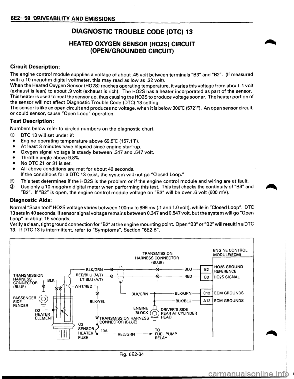
Circuit Description:
DIAGNOSTIC TROUBLE CODE (DTC) 13
HEATED OXYGEN SENSOR (H02S) CIRCUIT
(OPEN/GROUNDED CIRCUIT)
The engine control module supplies a voltage of about .45 volt between terminals "83" and "82". (If measured
with a
10 megohm digital voltmeter, this may read as low as .32 volt).
When the Heated Oxygen Sensor (H02S) reaches operating temperature, it varies this voltage from about .1 volt
(exhaust is lean) to about .9 volt (exhaust is rich). The H02S has a heater incorporated as part of the sensor.
This heater is used to
heatthe sensor up, thus causing the H02S to produce voltage sooner. The heater portion of
the sensor
will not affect Diagnostic Trouble Code (DTC) 13 setting.
The sensor
is like an open circuit and produces no voltage, when it is below 3oo·c (572.F). An open sensor circuit,
or could sensor, cause "Open Loop" operation.
Test Description:
Numbers below refer to circled numbers on the diagnostic chart.
• At least 3 minutes have elapsed since engine start-up.
• Oxygen signal voltage is steady between .347 and .547 volt.
• Throttle angle
above 9.8%.
• No DTC 21 or 31 is set.
• All above conditions are met for about 40 seconds.
If the conditions for a DTC 13 exist, the system will not go "Closed Loop."
® This test determines if the H02S is the problem or if the engine control module and wiring are at fault.
@ Use only a 10 megohm digital meter when performing this test. This test checks the continuity of "83" and
"82". If "82" is open, the engine control module voltage on "83" will be over .6 volt (600 mV).
Diagnostic Aids:
Normal "Scan tool" H02S voltage varies between 1 OOmv to 999 mv (.1 and 1.0 volt), while in "Closed Loop". DTC
13 sets in 40 seconds, if sensor signal voltage remains between 0.347 and 0.547 volt, but the system will go "Open
Loop"
in about 15 seconds.
Verify a
clean, tight ground connection for "82" at the engine mounting point. Open "83" or "82" will result in a DTC
13. If DTC 13 is intermittent, refer to "Symptoms", Section "6E2-8".
TRANSMISSION
HARNESS BLK CONNECTOR r 1
TRANSMISSION
HARNESS CONNECTOR
(BLUE) I /'< r--BLK/GRN ~~,---.,------«----BLU
RED/BLU (MIT) --« ! « RED
(BLUE) ~
PASSENGER Q SIDE
L T BLU (A/T) L
WHT/RED 1
P=H=~ r BLK/GRN ---.---BLK!GRN
BLK!YEL BLK!BLU FENDER
02 -----·'$ HEATER ELEMENT
02
l
ENGINE
BLOCK
TRANSMISSION HARNESS
-CONNECTOR (BLUE)
DRIVER'S SIDE REAR AT CYLINDER HEAD
SENSOR 10A TO
HEATER ---RED/GRN --• FUEL PUMP FUSE RELAY
Fig. 6E2-34
ENGINE CONTROL
MODULE(ECM)
H02S GROUND REFERENCE
H02S SIGNAL
ECM GROUNDS
ECM GROUNDS
•
Page 780 of 1928
6E2-84 DRIVEABILITY AND EMISSIONS
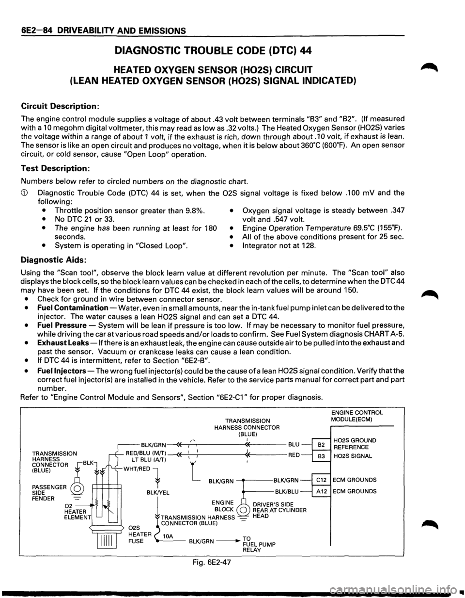
DIAGNOSTIC TROUBLE CODE (DTC) 44
HEATED OXYGEN SENSOR (H02S) CIRCUIT
(LEAN HEATED OXYGEN SENSOR (H02S) SIGNAL INDICATED)
Circuit Description:
The engine control module supplies a voltage of about .43 volt between terminals "83" and "82". (If measured
with a
10 megohm digital voltmeter, this may read as low as .32 volts.) The Heated Oxygen Sensor (H02S) varies
the
voltage within a range of about 1 volt, if the exhaust is rich, down through about .1 0 volt, if exhaust is lean.
The sensor is like an open circuit and produces no voltage, when it is below about 360°C (600°F). An open sensor
circuit,
or cold sensor, cause "Open Loop" operation.
Test Description:
Numbers below refer to circled numbers on the diagnostic chart.
CD Diagnostic Trouble Code (DTC) 44 is set, when the 02S signal voltage is fixed below .1 00 mV and the
following:
• Throttle
position sensor greater than 9.8%.
• No DTC 21 or 33. • Oxygen signal voltage is steady between .347
volt and .547 volt.
•
The engine has been running at least for 180 •
seconds. • • System is operating in "Closed Loop". •
Engine Operation Temperature 69SC (155°F).
All of the above conditions present for 25 sec .
Integrator not at 128 .
Diagnostic Aids:
Using the "Scan tool", observe the block learn value at different revolution per minute. The "Scan tool" also
displays
the block cells, so the block learn values can be checked in each ofthe cells, to determine when the DTC 44
may have been set.
If the conditions for DTC 44 exist, the block learn values will be around 150.
•
Check for ground in wire between connector sensor.
• Fuel Contamination-Water, even in small amounts, near the in-tank fuel pump inlet can be delivered to the
injector. The water causes a
lean H02S signal and can set a DTC 44.
• Fuel Pressure-System will be lean if pressure is too low. If may be necessary to monitor fuel pressure,
while driving the car at various road speeds and/or loads to confirm. See Fuel System diagnosis CHART A-5.
• Exhaust Leaks -lfthere is an exhaust leak, the engine can cause outside air to be pulled into the exhaust and
past the sensor.
Vacuum or crankcase leaks can cause a lean condition.
• If DTC 44 is intermittent, refer to Section "6E2-8".
• Fuel
Injectors-The wrong fuel injector(s) could be the cause of a lean H02S signal condition. Verify that the
correct
fuel injector(s) are installed in the vehicle. Refer to the service parts manual for correct part and part
number.
Refer
to "Engine Control Module and Sensors", Section "6E2-C1" for proper diagnosis.
TRANSMISSION
HARNESS
CONNECTOR
~BLK1
TRANSMISSION
HARNESS CONNECTOR
(BLUE) I /' BL~GRN~r-~----------~-------BLU
RED/BLU (MfT) --(( 1
1 ; « RED
(BLUE) ~
PASSENGER Q SIDE
LT BLU (A/T) L
WHT/RED 1
P:::l=t=t1 l BL~GRN ----.-----BL~GRN
BLK!YEL BL~BLU FENDER 02 --·S HEATER ELEMENT l
ENGINE
DRIVER'S SIDE BLOCK REAR AT CYLINDER
TRANSMISSION HARNESS _ HEAD CONNECTOR (BLUE)
10A -----BL~GRN ____ .,.... ~3EL PUMP RELAY
Fig. 6E2-47
ENGINE CONTROL
MODULE(ECM)
H02SGROUND REFERENCE
H02SSIGNAL
ECM GROUNDS
ECM GROUNDS
..
Page 782 of 1928
6E2-86 DRIVEABILITY AND EMISSIONS
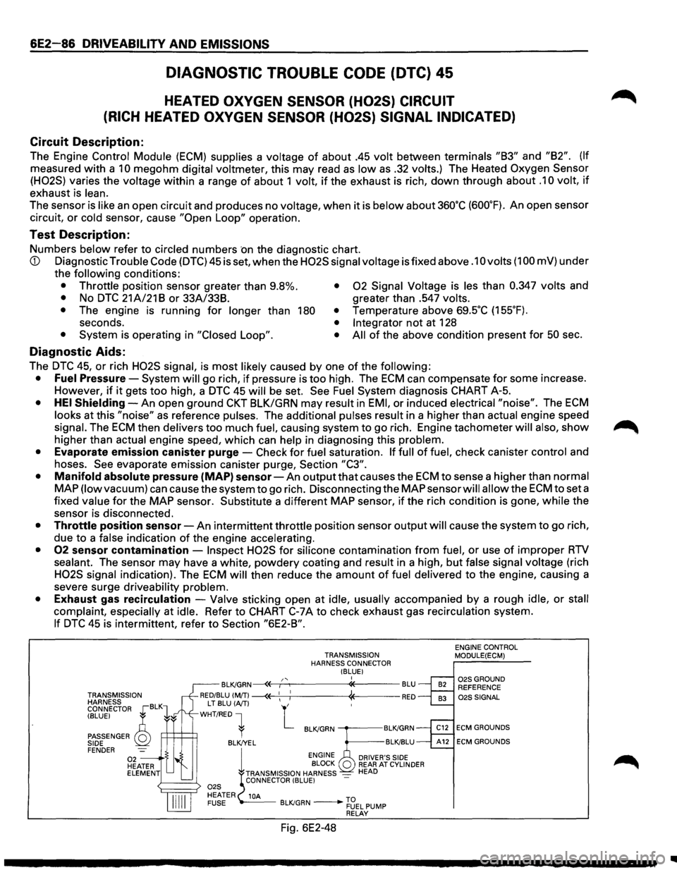
DIAGNOSTIC TROUBLE CODE (DTC) 45
HEATED OXYGEN SENSOR (H02S) CIRCUIT
(RICH
HEATED OXYGEN SENSOR (H02S) SIGNAL INDICATED)
Circuit Description:
The Engine Control Module (ECM) supplies a voltage of about .45 volt between terminals "83" and "82". (If
measured with a 10 megohm digital voltmeter, this may read as low as .32 volts.) The Heated Oxygen Sensor
(H02S)
varies the voltage within a range of about 1 volt, if the exhaust is rich, down through about .1 0 volt, if
exhaust is lean.
The sensor is like an open circuit and produces no voltage, when it is below about 360"C (600"F). An open sensor
circuit,
or cold sensor, cause "Open Loop" operation.
Test Description:
Numbers below refer to circled numbers ·on the diagnostic chart.
CD Diagnostic Trouble Code (DTC) 45 is set, when the H02S signal voltage is fixed above .1 0 volts (1 00 mV) under
the
following conditions:
• Throttle position sensor greater than 9.8%. • 02 Signal Voltage is les than 0.347 volts and
• No DTC 21 A/21 8 or 33A/338. greater than .547 volts.
•
The engine is running for longer than 180 • Temperature above 69.5"C (155"F).
seconds. • Integrator not at 128
• System is operating in "Closed Loop". • All of the above condition present for 50 sec.
Diagnostic Aids:
The DTC 45, or rich H02S signal, is most likely caused by one of the following:
• Fuel Pressure-System will go rich, if pressure is too high. The ECM can compensate for some increase.
However,
if it gets too high, a DTC 45 will be set. See Fuel System diagnosis CHART A-5.
• HEI Shielding-An open ground CKT BLK/GRN may result in EMI, or induced electrical "noise". The ECM
looks at this "noise" as reference pulses. The additional pulses result in a higher than actual engine speed
signal. The ECM then delivers too much fuel, causing system to go rich. Engine tachometer will also, show ~
higher than actual engine speed, which can help in diagnosing this problem.
• Evaporate emission canister purge-Check for fuel saturation. If full of fuel, check canister control and
hoses.
See evaporate emission canister purge, Section "C3".
• Manifold absolute pressure (MAP) sensor-An output that causes the ECM to sense a higher than normal
MAP (low vacuum) can causethesystemto go rich. Disconnecting the MAP sensor will allow the ECMtoseta
fixed value for the MAP sensor. Substitute a different MAP sensor, if the rich condition is gone, while the
sensor is disconnected.
• Throttle position sensor-An intermittent throttle position sensor output will cause the system to go rich,
due
to a false indication of the engine accelerating.
• 02 sensor contamination -Inspect H02S for silicone contamination from fuel, or use of improper RTV
sealant. The sensor may have a white, powdery coating and result in a high, but false signal voltage (rich
H02S signal indication). The ECM will then reduce the amount of fuel delivered to the engine, causing a
severe surge driveability problem.
• Exhaust gas recirculation -Valve sticking open at idle, usually accompanied by a rough idle, or stall
complaint, especially at idle. Refer to CHART C-7A to check exhaust gas recirculation system.
If DTC 45 is intermittent, refer to Section "6E2-8".
TRANSMISSION
HARNESS
CONNECTOR ,[BLK1
TRANSMISSION
HARNESS CONNECTOR !BLUE I I ,, BLK!GRN~E----r:......,-----"*----BLU
RED/BLU (MfT) ~ 1
1 1 RED
(BLUE) ~
PASSENGER Q SIDE FENDER
L T
BLU (AfT) L WHT/RED 1
R=+=+=:R l BLK!GRN -----BLK!GRN
BLK/YEL BLK!BLU
1
ENGINE
BLOCK Q TRANSMISSION HARNESS -CONNECTOR (BLUE) -
DRIVER'S SIDE REAR AT CYLINDER HEAD
10A BLK/GRN -~~EL PUMP RELAY
Fig. 6E2-48
ENGINE CONTROL MODULE(ECM)
02SGROUND REFERENCE 02S SIGNAL
ECM GROUNDS
ECM GROUNDS
..
Page 787 of 1928
FUEL SYSTEM
• CHECK:
• CHECK:
• CHECK:
• CHECK:
• CHECK:
• CHECK:
Fuel pump relay operation-pump should
turn "ON" for 2 seconds when ignition is
turned
"ON". Use CHART A-5.
Fuel injectors are correct for the vehicle.
Fuel
pressure, use CHART A-7.
Contaminated
fuel.
Engine fuse (visual inspect).
A
faulty in-tank fuel pump check valve will
allow
the fuel in the lines to drain back to
the tank after engine is stopped. To check
for this condition, perform fuel system
diagnosis CHART A-7.
IGNITION SYSTEM
• CHECK: For proper ignition voltage output with
spark tester J26792 or equivalent (ST-
125).
DRIVEABILITY AND EMISSIONS 6E2-91
• CHECK: Spark plugs. Remove spark plugs, check
for wet plugs, cracks, wear, improper
gap, burned electrodes, or heavy
deposits. Repair
or replace as necessary.
• CHECK: Bare or shorted wires.
• CHECK: Loose ignition coil ground.
ADDITIONAL CHECKS
• CHECK: Idle air control operation-use CHART C-
2C.
• CHECK: Basic engine problem. Refer to ENGINE
MECHANICAL DIAGNOSIS (SECTION
6A).
• CHECK: Service Bulletins for calibration updates.
SURGES AND/OR CHUGGLES
Definition: Engine power variation under steady
throttle or cruise. Feels like the car speeds
up and
slows down with no change in the
acceleration pedal.
PRELIMINARY CHECKS
• Perform the careful visual checks as described at
start
of "Symptoms," Section "6E2-B."
•
Be sure driver understands transmission
operation, and air conditioning compressor
operation
as explained in the owner's manual.
SENSORS
• CHECK: Heated oxygen sensor (H02S). The
H02S should respond quickly to different
throttle position, if it does not, check the
H02S for silicon or other contaminations
from fuel, or use of improper RTV sealant.
The sensor may have a white, powdery
coating and result in a high but false
signal voltage
(rich heated H02S signal
indication). The engine control module
will
then reduce the amount of fuel
delivered
to the engine, causing a severe
driveability problem. Also, watch for
green glycol contamination or cracking.
FUEL SYSTEM
• NOTICE: To determine ifthe condition is caused by
a rich
or lean system, the car should be
driven at the speed of the complaint.
Monitoring block learn will help identify a
problem.
Lean -Block learn above 142. Refer to
"Diagnostic Aids" on facing page of
diagnostic trouble code 44.
Rich -L.T. Fuel Trim above 118. Refer to
"Diagnostic Aids" on facing page of
diagnostic trouble code 45.
• CHECK: Fuel pressure while condition exists. Use
CHART A-7.
• CHECK: In-line fuel filter. Replace if dirty or
plugged.
IGNITION SYSTEM
• CHECK: For proper ignition voltage output using
spark tester (ST-125) J26792
or
equivalent .
• CHECK: Spark plugs. Remove spark plugs, check
for wet plugs, cracks, wear, improper
gap, burned electrodes, or heavy
deposits. Repair
or replace as necessary.
Also, check condition of electronic
ignition and spark plug wires.
• CHECK: Ignition timing. Using "Scan tool".
ADDITIONAL CHECKS
• CHECK: Engine control module grounds for being
clean, tight and in their proper location.
• CHECK: Vacuum lines for kinks or leaks.
• CHECK: Exhaust gas recirculation -There should
be no exhaust gas recirculation at idle.
Refer to CHART C-7.
• CHECK: Generator output voltage. Repair if less
than 9 or more than 16 volts.
Page 812 of 1928
6E2-116 DRIVEABILITY AND EMISSIONS
SECTION C-2
FUEL METERING SYSTEM
CONTENTS
General Description ...................... 6E2-116
Purpose ............................ 6E2-116
Modes of Operation .................... 6E2-117
Starting Mode ...................... 6E2-117
Clear Flood Mode .................... 6E2-117
RunMode ......................... 6E2-117
"Open Loop" ....................... 6E2-117
"Closed Loop" ...................... 6E2-117
Acceleration Mode ................... 6E2-117
Deceleration Mode ................... 6E2-117
Battery Positive Voltage Correction Mode ... 6E2-117
Fuel Cutoff Mode .................... 6E2-117
Fuel Metering System Components ........... 6E2-118
Fuel Supply System .................... 6E2-118
Fuel Pump Electrical Circuit ............... 6E2-118
Fuel Rail Assembly ..................... 6E2-118
Fuel Injectors ......................... 6E2-119
Fuel Injector Driver Operation ............. 6E2-119
Fuel Pressure Control Valve Assembly ....... 6E2-119
Throttle Body (TB) Assembly .............. 6E2-120
Idle Air Control (lAC) Valve .............. 6E2-120
Throttle Position (TP) Sensor ............ 6E2-121
Induction Air Control Plate System ......... 6E2-121
Diagnosis . . . . . . . . . . . . . . . . . . . . . . . . . . . . . 6E2-121
Fuel Metering System . .
. . . . . . . . . . . . . . . . 6E2-121
Fuel System Pressure Test ............... 6E2-121
Idle Air Control (lAC) Valve . .
. . . . . . . . . . . . . 6E2-121
Induction Air Control Plate System ......... 6E2-122
On-Vehicle Service ...................... 6E2-122
Fuel Pump Relay . . . . . . . . . . . . . . . . . . . . . . 6E2-122
Multipart Fuel Injection Components . . . . . . . . 6E2-122 Fuel Pressure Relief Procedure . . . . . . . . . . 6E2-122
Fuel Rail Assembly . . . . . . . . . . . . . . . . . . . . 6E2-122
Unit Repair ............................ 6E2-123
Fuel Injector/Rail ...................... 6E2-123
Throttle Body Assembly . . . . . . . . . . . . . . . . . 6E2-124
Throttle Body (TB) . . . . . . . . . . . . . . . . . . . 6E2-125
Throttle Position (TP) Sensor . . . . . . . . . . . . . 6E2-126
Idle Air Control (lAC) Valve ............... 6E2-126
Minimum Throttle Body (TB) Position Check ... 6E2-127
Chart C-2A Injector Balance ................ 6E2-128
Chart C-2C Idle Air Control (lAC) System Check .. 6E2-130
Chart C-2D Induction Air Control Plate
System Check . .
. . . . . . . . . . . . . . . . . . . . . . 6E2-132
GENERAL DESCRIPTION
PURPOSE
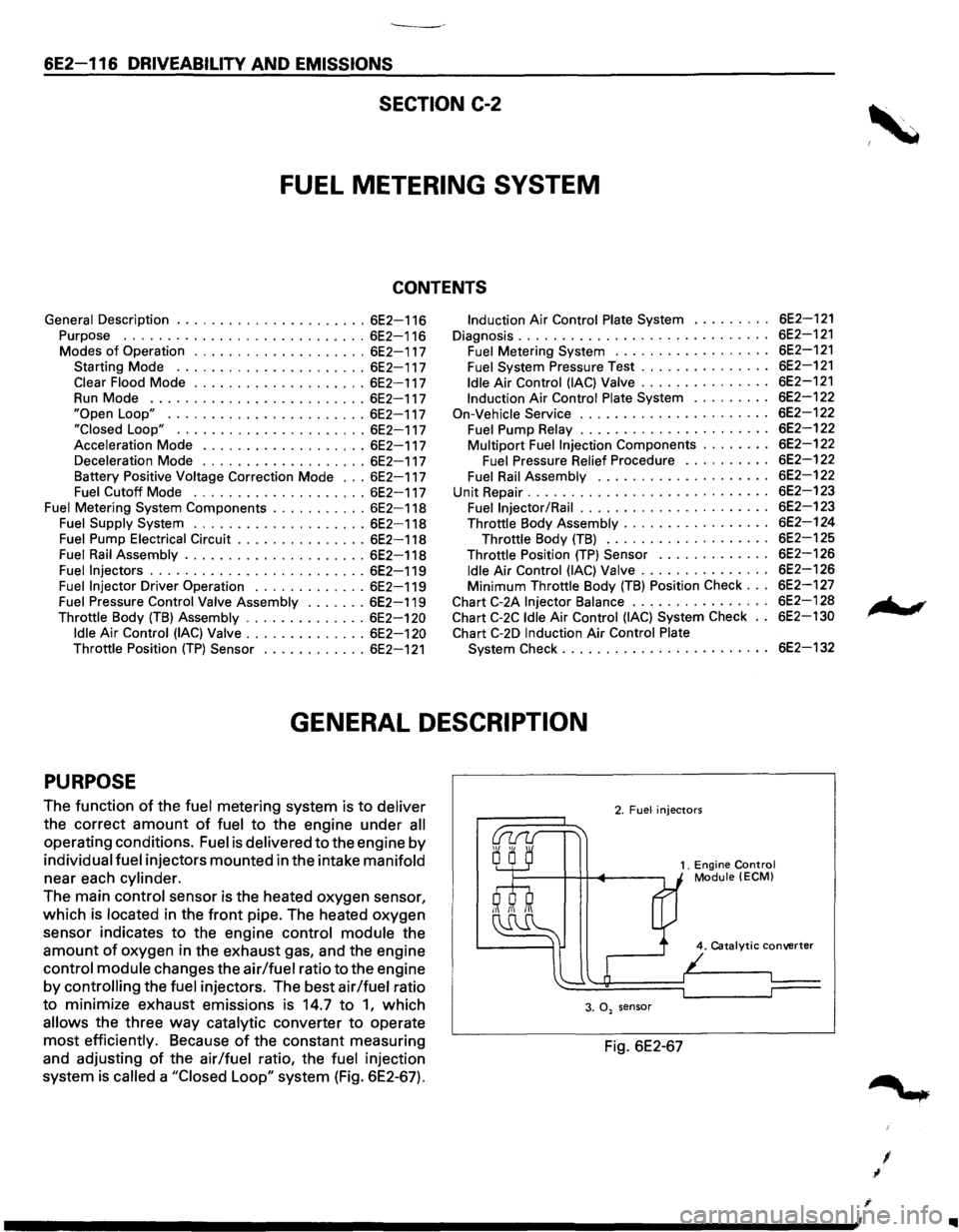
The function of the fuel metering system is to deliver
the correct amount of fuel to the engine under all
operating conditions. Fuel is delivered to the engine by
individual fuel injectors mounted in the intake manifold
near each cylinder.
The main control sensor is the heated oxygen sensor,
which is located in the front pipe. The heated oxygen
sensor indicates
to the engine control module the
amount of oxygen in the exhaust gas, and the engine
control module changes the air/fuel ratio to the engine
by
controlling the fuel injectors. The best air/fuel ratio
to minimize exhaust emissions is 14.7 to
1, which
allows the three way catalytic converter to operate
most efficiently. Because of the constant measuring
and adjusting
of the air/fuel ratio, the fuel injection
system
is called a "Closed Loop" system (Fig. 6E2-67).
2. Fuel injectors
1. Engine Control Module (ECMl
4. Catalytic converter
3. 0, sensor
Fig. 6E2-67
I
I
Page 813 of 1928
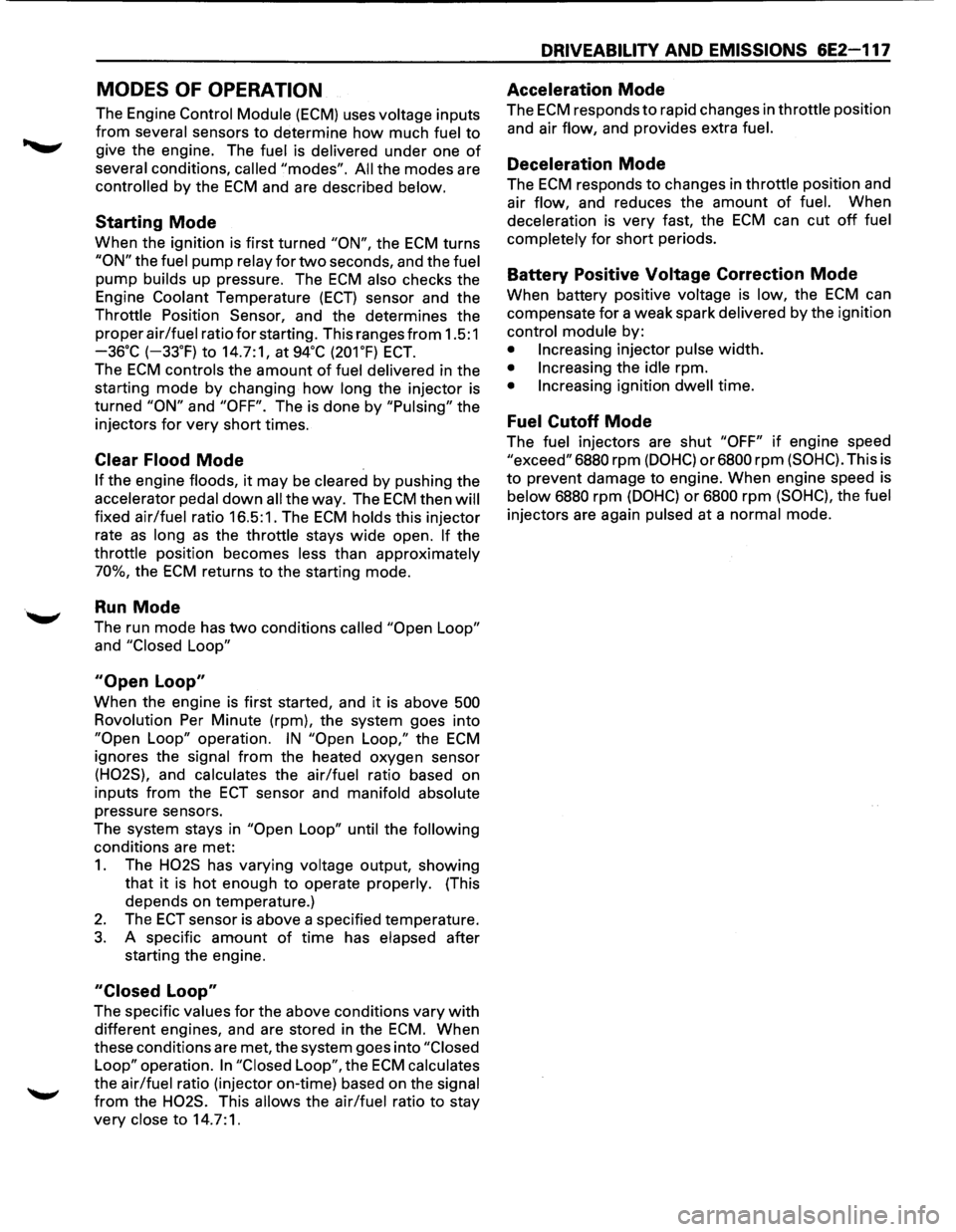
MODES OF OPERATION
The Engine Control Module (ECM) uses voltage inputs
from several sensors to determine how much fuel to
give the engine. The fuel is delivered under one of
several conditions, called "modes". All the modes are
controlled by the ECM and are described below.
Starting Mode
When the ignition is first turned "ON", the ECM turns
"ON" the fuel pump relay for two seconds, and the fuel
pump builds up pressure. The ECM also checks the
Engine
Coolant Temperature (ECT) sensor and the
Throttle Position Sensor, and the determines the
proper
air/fuel ratio for starting. This ranges from 1.5:1
-36·c (-33.F) to 14.7:1, at 94•c (201.F) ECT.
The ECM controls the amount of fuel delivered in the
starting mode by changing
how long the injector is
turned
"ON" and "OFF". The is done by "Pulsing" the
injectors
for very short times.
Clear Flood Mode
If the engine floods, it may be cleared by pushing the
accelerator pedal down all the way. The ECM then will
fixed air/fuel ratio 16.5:1. The ECM holds this injector
rate
as long as the throttle stays wide open. If the
throttle position becomes less than approximately
70%, the ECM returns to the starting mode.
Run Mode
The run mode has two conditions called "Open Loop"
and "Closed Loop"
"Open Loop"
When the engine is first started, and it is above 500
Rovolution Per Minute (rpm), the system goes into
"Open Loop" operation. IN "Open Loop," the ECM
ignores the signal from the heated oxygen sensor
(H02S), and calculates the air/fuel ratio based on
inputs
from the ECT sensor and manifold absolute
pressure sensors.
The system stays in
"Open Loop" until the following
conditions are met:
1. The H02S has varying voltage output, showing
that
it is hot enough to operate properly. (This
depends on temperature.)
2. The ECT sensor is above a specified temperature.
3. A specific amount of time has elapsed after
starting the engine.
"Closed Loop"
The specific values for the above conditions vary with
different engines, and are stored in the ECM. When
these conditions are met, the system goes into
"Closed
Loop"
operation. In "Closed Loop", the ECM calculates
the air/fuel ratio (injector on-time) based on the signal
from the H02S. This allows the air/fuel ratio to stay
very close to 14.7:1.
DRIVEABILITV AND EMISSIONS 6E2-117
Acceleration Mode
The ECM responds to rapid changes in throttle position
and air
flow, and provides extra fuel.
Deceleration Mode
The ECM responds to changes in throttle position and
air
flow, and reduces the amount of fuel. When
deceleration is very fast, the ECM can cut off fuel
completely
for short periods.
Battery Positive Voltage Correction Mode
When battery positive voltage is low, the ECM can
compensate
for a weak spark delivered by the ignition
control module by:
• Increasing injector pulse width.
• Increasing the idle rpm.
• Increasing ignition dwell time.
Fuel Cutoff Mode
The fuel injectors are shut "OFF" if engine speed
"exceed" 6880 rpm (DOHC) or6800 rpm (SOHC). This is
to prevent damage to engine. When engine speed is
below 6880 rpm (DOHC) or 6800 rpm (SOHC), the fuel
injectors are again pulsed at a normal mode.
Page 814 of 1928
6E2-118 DRIVEABILITV AND EMISSIONS
FUEL METERING SYSTEM COMPONENTS
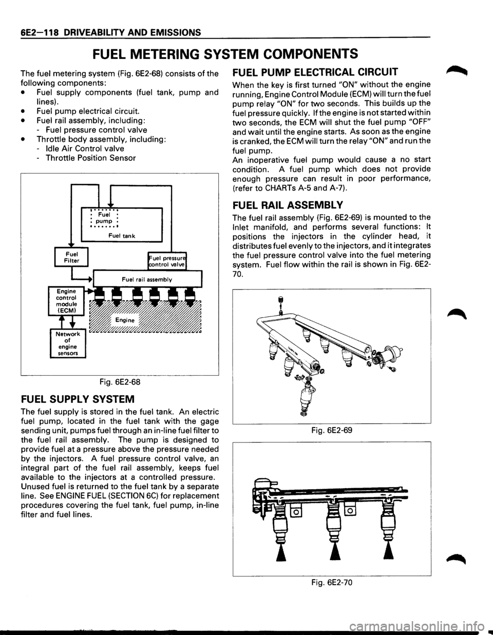
The fuel metering system (Fig. 6E2-68) consists of the
following components:
• Fuel supply components (fuel tank, pump and
lines).
• Fuel
pump electrical circuit.
• Fuel rail assembly, including:
-Fuel pressure control valve
• Throttle
body assembly, including:
-Idle Air Control valve
-Throttle Position Sensor
engine
sensors
• Fuel • :pump : ........
Fuel tank
Fig. 6E2-68
FUEL SUPPL V SYSTEM
The fuel supply is stored in the fuel tank. An electric
fuel
pump, located in the fuel tank with the gage
sending unit, pumps
fuel through an in-line fuel filter to
the
fuel rail assembly. The pump is designed to
provide
fuel at a pressure above the pressure needed
by the injectors. A fuel pressure control valve, an
integral part of the fuel rail assembly, keeps fuel
available
to the injectors at a controlled pressure.
Unused
fuel is returned to the fuel tank by a separate
line. See ENGINE FUEL (SECTION 6C) for replacement
procedures covering the fuel tank, fuel pump, in-line
filter
and fuel lines.
FUEL PUMP ELECTRICAL CIRCUIT
When the key is first turned "ON" without the engine
running, Engine
Control Module (ECM) will turn the fuel
pump relay "ON" for two seconds. This builds up the
fuel pressure quickly. lfthe engine is not started within
two seconds, the ECM will shut the fuel pump "OFF"
and wait until the engine starts. As soon as the engine
is cranked, the
ECM will turn the relay "ON" and run the
fuel pump.
An inoperative
fuel pump would cause a no start
condition. A
fuel pump which does not provide
enough pressure can
result in poor performance,
(refer to CHARTs A-5 and A-7).
FUEL RAIL ASSEMBL V
The fuel rail assembly (Fig. 6E2-69) is mounted to the
Inlet manifold, and performs several functions: It
positions the injectors in the cylinder head, it
distributes fuel evenly to the injectors, and it integrates
the
fuel pressure control valve into the fuel metering
system.
Fuel flow within the rail is shown in Fig. 6E2-
70.
Fig. 6E2-69
Fig. 6E2-70