four wheel drive ISUZU TROOPER 1995 Workshop Manual
[x] Cancel search | Manufacturer: ISUZU, Model Year: 1995, Model line: TROOPER, Model: ISUZU TROOPER 1995Pages: 1928
Page 14 of 1928
OA-10 GENERAL INFORMATION
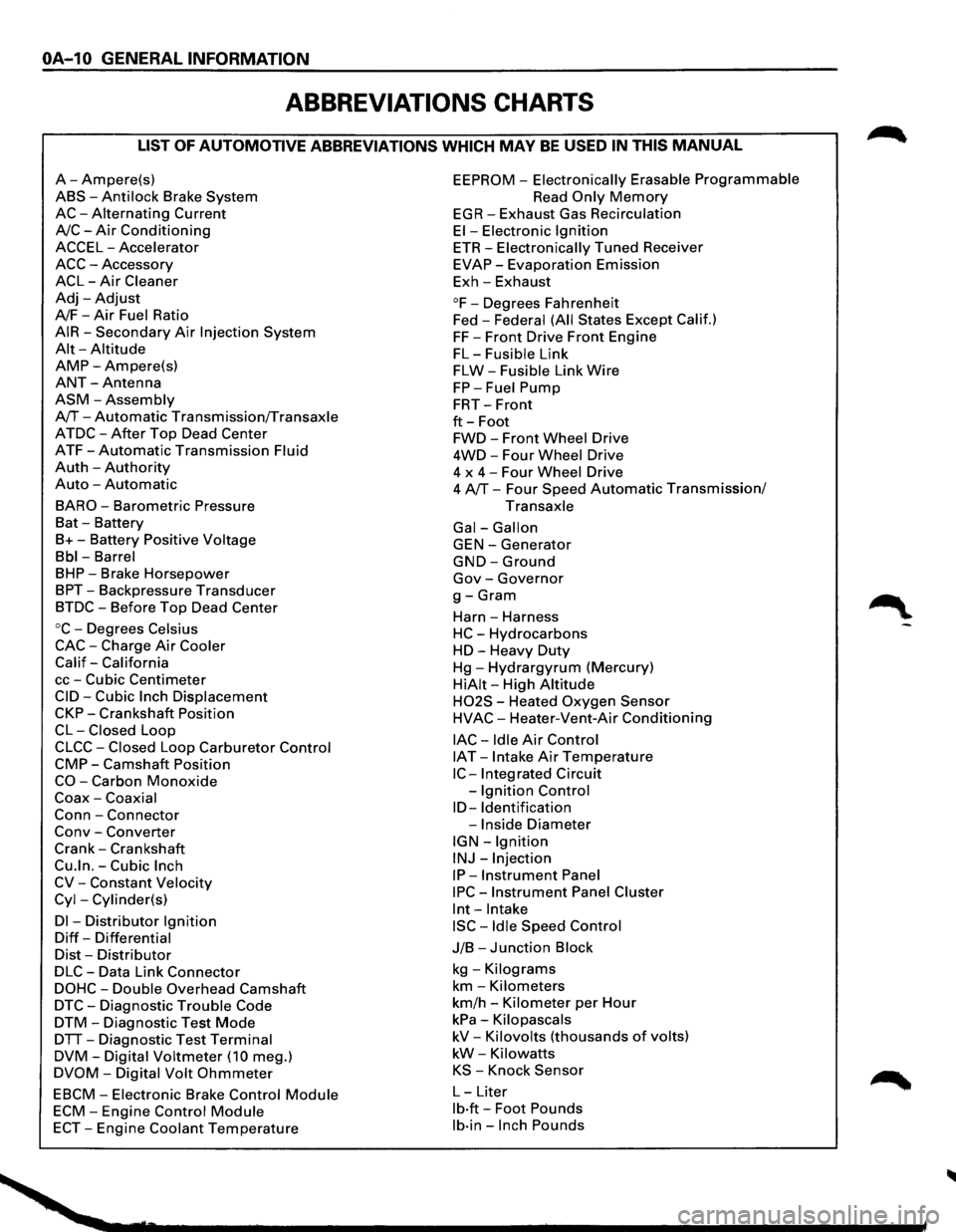
ABBREVIATIONS CHARTS
LIST OF AUTOMOTIVE ABBREVIATIONS WHICH MAY BE USED IN THIS MANUAL
A-Ampere(s)
ABS-Anti lock Brake System
AC-Alternating Current
A/C-Air Conditioning
ACCEL-Accelerator
ACC-Accessory
ACL-Air Cleaner
Adj-Adjust
A/F-Air Fuel Ratio
AIR-Secondary Air Injection System
Alt-Altitude
AMP-Ampere(s)
ANT-Antenna
ASM-Assembly
A/T-Automatic Transmission/Transaxle
ATDC-After Top Dead Center
ATF-Automatic Transmission Fluid
Auth -Authority
Auto -Automatic
BARO-Barometric Pressure
Bat -Battery
B+-Battery Positive Voltage
Bbl-Barrel
BHP-Brake Horsepower
BPT-Backpressure Transducer
BTDC-Before Top Dead Center
oc-Degrees Celsius
CAC-Charge Air Cooler
Calif-California
cc-Cubic Centimeter
CID-Cubic Inch Displacement
CKP-Crankshaft Position
CL-Closed Loop
CLCC-Closed Loop Carburetor Control
CMP-Camshaft Position
CO-Carbon Monoxide
Coax-Coaxial
Conn-Connector
Conv -Converter
Crank-Crankshaft
Cu.ln.-Cubic Inch
CV-Constant Velocity
Cyl-Cylinder(s)
Dl -Distributor Ignition
Diff-Differential
Dist-Distributor
DLC-Data Link Connector
DOHC-Double Overhead Camshaft
DTC-Diagnostic Trouble Code
DTM-Diagnostic Test Mode
DTT-Diagnostic Test Terminal
DVM-Digital Voltmeter (10 meg.)
DVOM-Digital Volt Ohmmeter
EBCM-Electronic Brake Control Module
ECM-Engine Control Module
ECT-Engine Coolant Temperature
EEPROM -Electronically Erasable Programmable
Read Only Memory
EGR-Exhaust Gas Recirculation
El-Electronic Ignition
ETR-Electronically Tuned Receiver
EVAP-Evaporation Emission
Exh-Exhaust
°F-Degrees Fahrenheit
Fed -
Federal (All States Except Calif.)
FF-Front Drive Front Engine
FL-Fusible Link
FLW-Fusible Link Wire
FP-Fuel Pump
FRT-Front
ft-Foot
FWD-Front Wheel Drive
4WD-Four Wheel Drive
4 x
4-Four Wheel Drive
4 A/T-Four Speed Automatic Transmission/
Transaxle
Gal-Gallon
GEN-Generator
GND-Ground
Gov-Governor
g-Gram
Harn -Harness
HC-Hydrocarbons
HD-Heavy Duty
Hg-Hydrargyrum (Mercury)
HiAit-High Altitude
H02S - Heated Oxygen Sensor
HVAC-Heater-Vent-Air Conditioning
lAC-Idle Air Control
IAT -Intake Air Temperature
IC-Integrated Circuit
-
Ignition Control
ID-Identification
-Inside Diameter
IGN-Ignition
INJ-Injection
IP-Instrument Panel
IPC-Instrument Panel Cluster
lnt-Intake
ISC-Idle Speed Control
J/B-Junction Block
kg -Kilograms
km-Kilometers
km/h -Kilometer per Hour
kPa-Kilopascals
kV-Kilovolts (thousands of volts)
kW-Kilowatts
KS -Knock Sensor
L-Liter
lb·ft-Foot Pounds
lb·in-Inch Pounds
Page 15 of 1928
LF -Left Front
LH -Left Hand
LR-Left Rear
LS-Left Side
LWB-Long Wheel Base
L-4-In-line Four Cylinder Engine
MAF-Mass Air Flow
MAN-Manual
MAP-Manifold Absolute Pressure
Max-Maximum
MC-Mixture Control
MFI-Multipart Fuel Injection
MIL-Malfunction Indicator Lamp
Min-Minimum
mm-Millimeter
MPG-Miles per Gallon
MPH-Miles per Hour
M!f-Manual Transmission!fransaxle
MV-Millivolt
NA-Natural Aspirated
NC-Normally Closed
N·m-Newton Meters
NO-Normally Open
NOx-Nitrogen, Oxides of
OBD-On-Board Diagnostic
OD-Outside Diameter
0/D-Over Drive
OHC-Overhead Camshaft
OL-Open Loop
02-Oxygen
02S -Oxygen Sensor
PAIR-Pulsed Secondary Air Injection System
P/B-Power Brakes
PCM-Powertrain Control Module
PCV-Positive Crankcase Ventilation
PRESS-Pressure
PROM-Programmable Read Only Memory
PNP-Park/Neutral Position
P/S-Power Steering
PSI-Pounds per Square Inch
PSP-Power Steering Pressure
Pt.-Pint
Pri -Primary
PWM-Pulse Width Modulate
Ot-Quart
REF-Reference
RF -Right Front
RFI-Radio Frequency Interference
RH-Right Hand
RPM-Revolutions per Minute
RPM Sensor-Engine Speed Sensor
RPO-Regular Production Option
RR-Right Rear
RS-Right Side
RTV-Room Temperature Vulcanizing
RWAL-Rear Wheel Anti lock Brake
RWD-Rear Wheel Drive
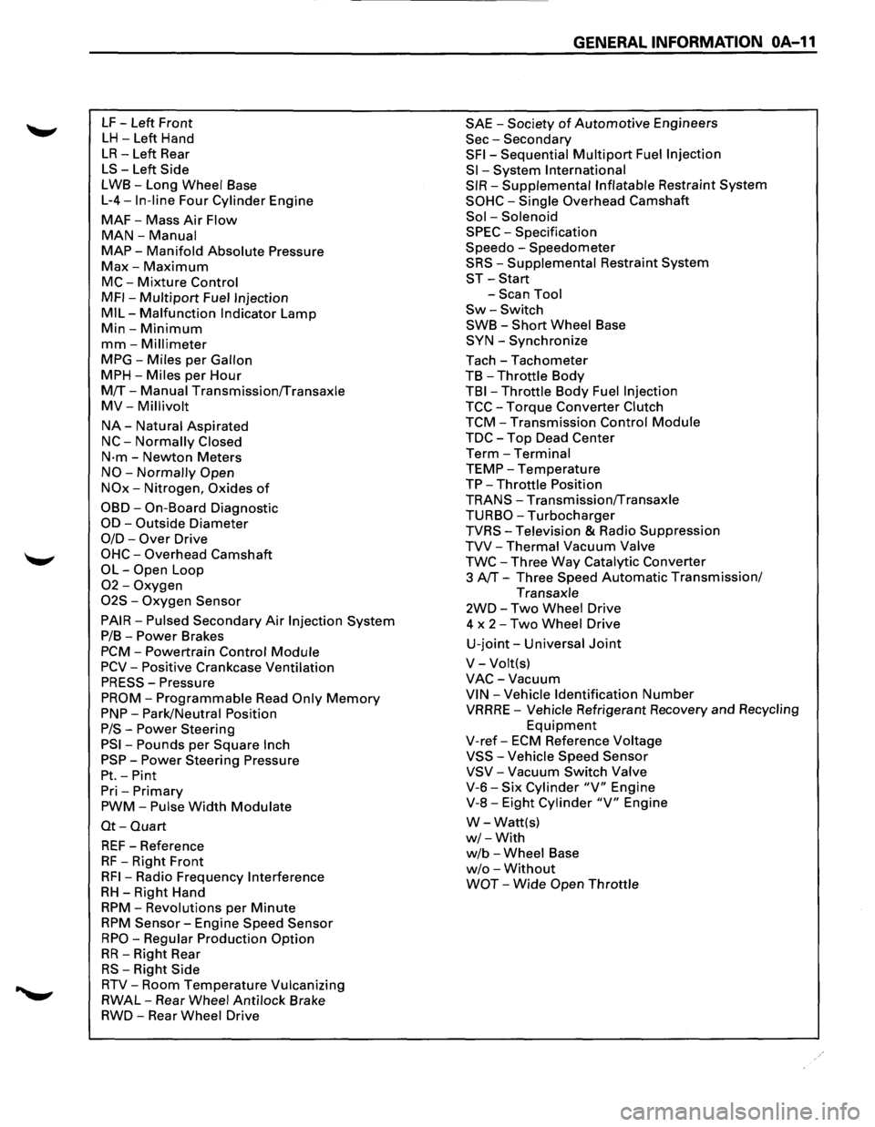
GENERAL INFORMATION OA-11
SAE -Society of Automotive Engineers
Sec-Secondary
SFI-Sequential Multipart Fuel Injection
Sl-System International
SIR-Supplemental Inflatable Restraint System
SOHC-Single Overhead Camshaft
Sol -Solenoid
SPEC -Specification
Speedo -Speedometer
SRS-Supplemental Restraint System
ST-Start
-Scan Tool
Sw-Switch
SWB-Short Wheel Base
SYN-Synchronize
Tach-Tachometer
TB
-Throttle Body
TBI-Throttle Body Fuel Injection
TCC-Torque Converter Clutch
TCM-Transmission Control Module
TDC-Top Dead Center
Term-Terminal
TEMP-Temperature
TP-Throttle Position
TRANS-Transmission!fransaxle
TURBO-Turbocharger
TVRS-Television & Radio Suppression
TVV-Thermal Vacuum Valve
TWC-Three Way Catalytic Converter
3
AfT-Three Speed Automatic Transmission/
Transaxle
2WD-Two Wheel Drive
4 x
2-Two Wheel Drive
U-joint-Universal Joint
V-Volt(s)
VAC-Vacuum
VIN-Vehicle Identification Number
VRRRE -Vehicle Refrigerant Recovery and Recycling
Equipment
V-ref-ECM Reference Voltage
VSS-Vehicle Speed Sensor
VSV-Vacuum Switch Valve
V-6-Six Cylinder "V" Engine
V-8-Eight Cylinder "V" Engine
W-Watt(s)
w/-With
w/b -Wheel Base
w/o -Without
WOT-Wide Open Throttle
Page 130 of 1928
3-10 DIAGNOSIS
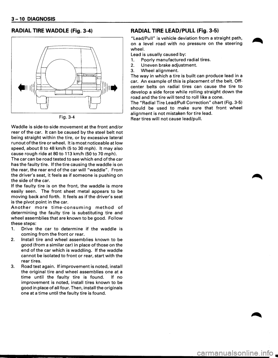
RADIAL TIRE WADDLE (Fig. 3-4)
Fig. 3-4
Waddle is side-to-side
movement at the front and/or
rear of the car. It can be caused by the steel belt not
being straight within the tire, or by excessive lateral
runout of the tire or wheel. It is most noticeable at low
speed, about 8 to 48 km/h (5 to 30 mph). It may also
cause
rough ride at 80 to 113 km/h (50 to 70 mph).
The car can be road tested
to see which end of the car
has
the faulty tire. If the tire causing the waddle is on
the rear, the rear end
of the car will "waddle". From
the
driver's seat, it feels as if someone is pushing on
the side
of the car.
If the faulty tire is on the front, the waddle is more
easily seen. The front sheet metal appears to be
moving back and forth. It feels as if the driver's seat
is
the pivot point in the car.
Another more time-consuming method of
determining the faulty tire is substituting tire and
wheel assemblies
that are known to be good. Follow
these steps:
1. Drive the car to determine if the waddle is
coming from the front or rear.
2. Install tire and wheel assemblies known to be
good (from a similar car) in place ofthose on the
end
of the car which is waddling. If the waddle
cannot be isolated to front or rear, start with the
rear tires.
3. Road test again. If improvement is noted, install
the original tire and wheel assemblies one at a
time until the faulty tire is found. If no
improvement is noted, install tires known to be
good in place of all four. Then, install the originals
one at a
time until the faulty tire is found.
RADIAL TIRE LEAD/PULL (Fig. 3-5)
"Lead/Pull" is vehicle deviation from a straight path,
on a level road
with no pressure on the steering
wheel.
Lead is usually caused by:
1. Poorly manufactured radial tires.
2. Uneven brake adjustment.
3. Wheel alignment.
The
way in which a tire is built can produce lead in a
car.
An example of this is placement of the belt. Off
center belts on radial tires can cause the tire to
develop a side force while rolling straight down the
road and the tire will tend to roll like a cone.
The
"Radial Tire Lead/Pull Correction" chart (Fig. 3-5)
should be used to make sure that front wheel
alignment is not mistaken for tire lead.
Rear
tires will not cause lead/pull.
II
Page 245 of 1928
REAR AXLE 48-3
DIAGNOSIS OF REAR AXLE NOISE
Many noises that seem to come from the rear axle
actually
originate from other sources such as tires,
road surface, wheel bearings, engine, transmission,
muffler,
or body drumming. Investigate to find the
source
ofthe noise before disassembling the rear axle.
Rear axles,
like any other mechanical device, are not
absolutely quiet but should be considered quiet unless
some abnormal noise is present.
To make a systematic check
for axle noise, observe the
following:
1. Select a level asphalt road to reduce tire noise and
body drumming.
2. Check rear axle lubricant level to assure correct
level, and then drive the vehicle far enough to
thoroughly warm up the rear axle lubricant.
3. Note the speed at which noise occurs. Stop the
vehicle and put the transmission in neutral. Run
the engine speed
slowly up and down to
determine if the noise is caused by exhaust,
muffler noise, or other engine conditions.
4. Tire noise changes with different road surfaces;
axle noises do not. Temporarily inflate all tires to
344
kPa (50 psi) (for test purposes only). This will
change noise caused by tires but will not affect
noise caused by the rear
axle.
Rear axle nose usually stops when coasting at
speeds under
48 km/h (30 mph); however, tire
noise continues
with a lower tone. Rear axle noise
usually changes when comparing pull and coast,
but tire noise stays about the same.
Distinguish between tire noise and rear
axle noise
by noting
if the noise changes with various
speeds
or sudden acceleration and deceleration.
Exhaust and
axle noise vary under these
conditions,
while tire noise remains constant and
is more pronounced at speeds
of 32 to 48 km/h
(20 to 30 mph). Further check for tire noise by
driving the vehicle
over smooth pavements or dirt
roads (not gravel) with the tires at normal
pressure.
If the noise is caused by tires, it will
change noticeably with changes in road surface.
5. Loose or rough front wheel bearings will cause
noise
which may be confused with rear axle
noise; however, front wheel bearing noise does
not change when comparing drive and coast.
Light application
of the brake while holding
vehicle speed steady
will often cause wheel
bearing noise to diminish. Front wheel bearings
may be checked for noise by jacking up the
wheels and spinning them
or by shaking the
wheels
to determine if bearings are loose.
6. Rear suspension rubber bushings and spring
insulators dampen
out rear axle noise when
correctly installed. Check to see that there is no
link or rod loosened or metal-to-metal contact.
7. Make sure that there is no metal-to-metal contact
between the
floor and the frame.
After the noise has been determined to be in the axle,
the type of axle noise should be determined, in order to
make any necessary repairs.
GEAR NOISE
Gear noise (whine) is audible from 32 to 89 km/h (20 to
55 mph) under four driving conditions.
1. In drive under acceleration or heavy pull.
2. Driving under load or under constant speed.
3. When using enough throttle to keep the vehicle
from driving the engine while the vehicle slows
down gradually (engine still pulls slightly).
4. When coasting with the vehicle in gear and the
throttle closed. The gear noise is
usually more
noticeable between 48 and 64
km/h (30 and 40
mph) and 80 and 89 km/h (50 and 55 mph).
BEARING NOISE
Bad bearings generally produce a rough growl or
grating sound, rather than the whine typical of gear
noise. Bearing noise frequently
"wow-wows" at
bearing rpm, indicating a bad pinion
or rear axle side
bearing. This noise can
be confused with rear wheel
bearing noise.
REAR WHEEL BEARING NOISE
Rear wheel bearing noise continues to be heard while
coasting at low speed with transmission in the neutral.
Noise may diminish by gentle braking. Jack up the rear
wheels, spin them by hand and
listen for noise at the
hubs. Replace any faulty
wheel bearings.
KNOCK AT LOW SPEEDS
Low speed knock can be caused by worn universal
joints or a side gear hub counter bore in the cage that is
worn oversize. Inspect and replace universal joints or
cage and side gears as required.
BACKLASH CLUNK
Excessive clunk on acceleration and deceleration can
be caused by a worn rear axle pinion shaft, a worn
cage, excessive clearance between the axle and the
side gear splines, excessive clearance between the
side gear hub and the counterbore in the cage,
worn
pinion and side gear teeth, worn thrust washers, or
excessive drive pinion and ring gear backlash.
Remove
worn parts and replace as required. Select
close-fitting parts when possible. Adjust pinion and
ring gear backlash.
Page 281 of 1928
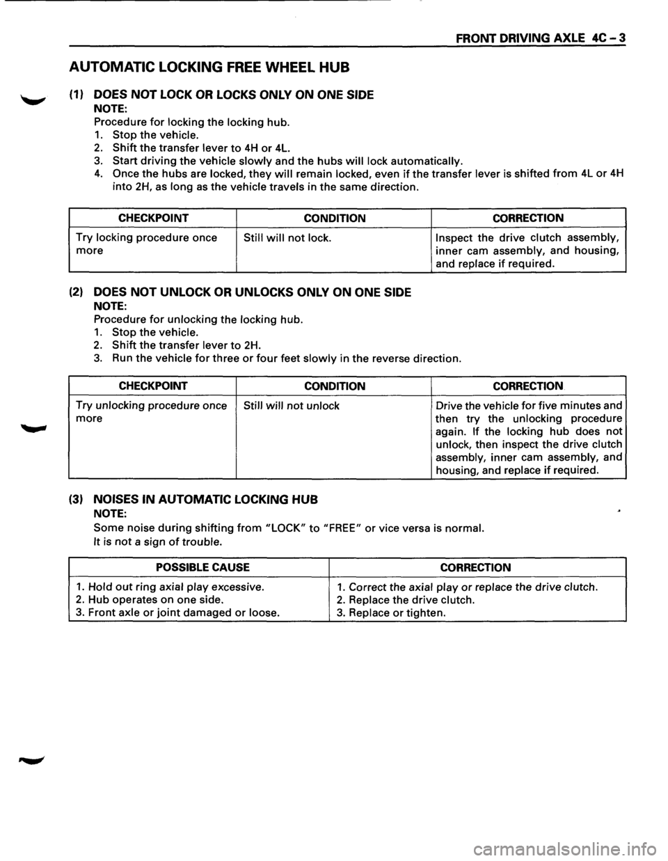
AUTOMATIC LOCKING FREE WHEEL HUB
(1) DOES NOT LOCK OR LOCKS ONLY ON ONE SIDE
NOTE:
Procedure for locking the locking hub.
1. Stop the vehicle.
2. Shift the transfer lever to 4H or 4L.
FRONT DRIVING AXLE 4C-3
3. Start driving the vehicle slowly and the hubs will lock automatically.
4. Once the hubs are locked, they will remain locked, even if the transfer lever is shifted from 4L or 4H
into 2H, as long as the vehicle travels in the same direction.
CHECKPOINT
CONDITION
Try locking procedure once Still will not lock.
more
(2) DOES NOT UNLOCK OR UNLOCKS ONLY ON ONE SIDE
NOTE:
Procedure for unlocking the locking hub.
1. Stop the vehicle.
2. Shift the transfer lever to 2H.
CORRECTION
Inspect the drive clutch assembly,
inner cam assembly, and housing,
and replace
if required.
3. Run the vehicle for three or four feet slowly in the reverse direction.
CHECKPOINT
CONDITION CORRECTION
Try unlocking procedure once Still will not unlock Drive the vehicle for five minutes and
more
(3) NOISES IN AUTOMATIC LOCKING HUB
NOTE:
then try the unlocking procedure
again.
If the locking hub does not
unlock, then inspect the drive clutch
assembly,
inner cam assembly, and
housing, and replace
if required.
Some noise during shifting from "LOCK" to "FREE" or vice versa is normal.
It
is not a sign of trouble.
POSSIBLE CAUSE CORRECTION
1. Hold out ring axial play excessive. 1. Correct the axial play or replace the drive clutch.
2. Hub operates on one side. 2. Replace the drive clutch.
3. Front axle or joint damaged or loose. 3. Replace or tighten.
Page 331 of 1928
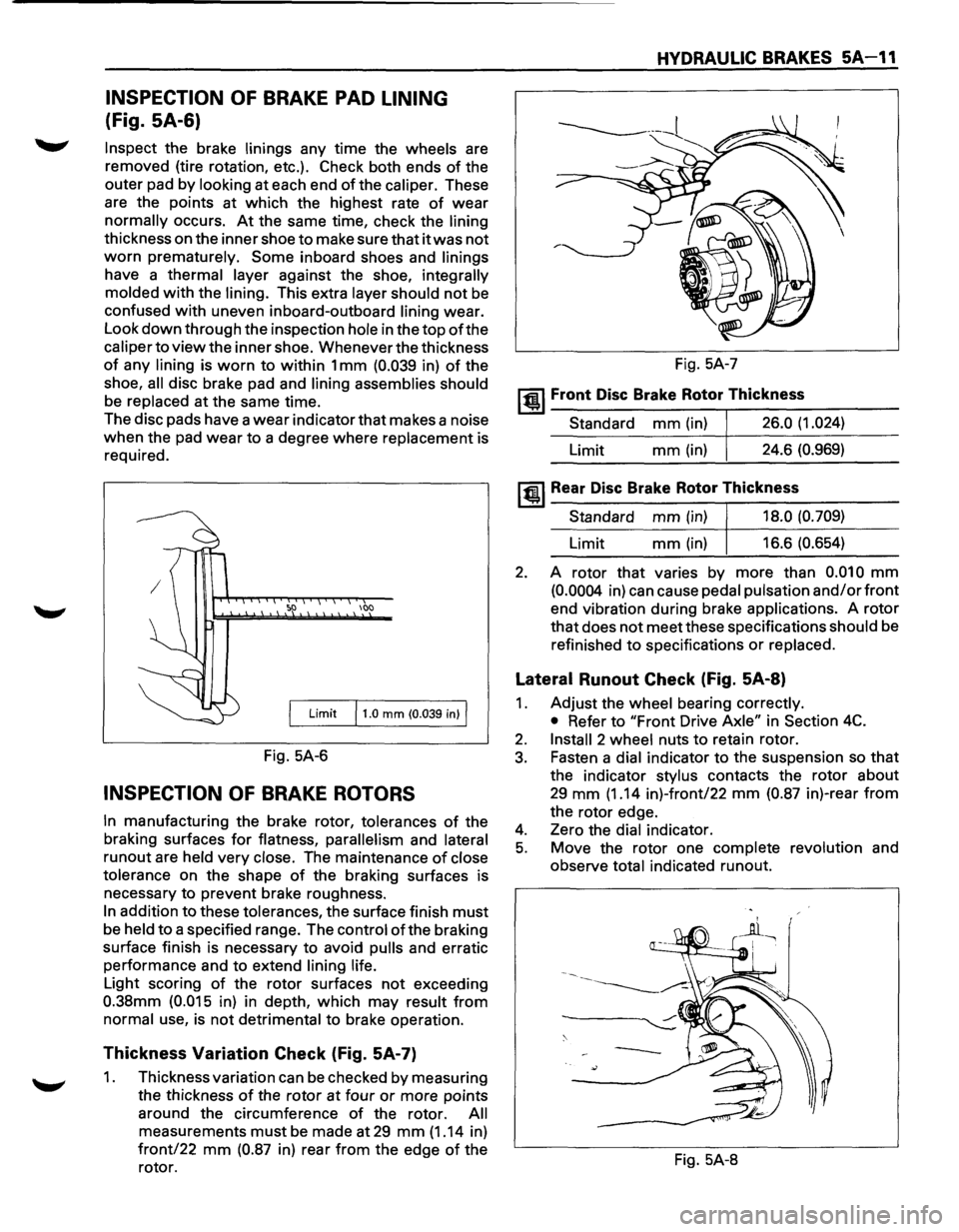
INSPECTION OF BRAKE PAD LINING
(Fig. SA-6)
Inspect the brake linings any time the wheels are
removed (tire rotation, etc.). Check both ends
of the
outer pad by
looking at each end of the caliper. These
are the points at which the highest rate
of wear
normally occurs. At the same time, check the lining
thickness on the inner shoe to make sure that it was not
worn prematurely. Some inboard shoes and linings
have a thermal layer against the shoe, integrally
molded
with the lining. This extra layer should not be
confused with uneven inboard-outboard lining wear.
Look
down through the inspection hole in the top of the
caliper to view the inner shoe. Whenever the thickness
of any lining is worn to within 1 mm (0.039 in) of the
shoe,
all disc brake pad and lining assemblies should
be replaced at the same time.
The disc pads have a
wear indicator that makes a noise
when the pad wear to a degree where replacement is
required.
100
Limit 11.0 mm (0.039 in) I
Fig. 5A-6
INSPECTION OF BRAKE ROTORS
In manufacturing the brake rotor, tolerances of the
braking surfaces
for flatness, parallelism and lateral
runout are held very close. The maintenance of close
tolerance
on the shape of the braking surfaces is
necessary to prevent brake roughness.
In addition to these tolerances, the surface finish must
be held to a specified range. The control ofthe braking
surface finish is necessary to avoid
pulls and erratic
performance and to extend
lining life.
Light scoring of the rotor surfaces not exceeding
0.38mm (0.015 in) in depth, which may result from
normal use, is not detrimental to brake operation.
Thickness Variation Check (Fig. 5A-7)
1. Thickness variation can be checked by measuring
the thickness
of the rotor at four or more points
around the circumference
of the rotor. All
measurements must be made at 29 mm (1.14 in)
front/22 mm (0.87 in) rear from the edge of the
rotor.
HYDRAULIC BRAKES 5A-11
Fig. 5A-7
~~~ Front Disc Brake Rotor Thickness
Standard mm (in) 26.0 (1.024)
Limit mm(in) 24.6 (0.969)
~~~Rear Disc Brake Rotor Thickness
Standard mm (in) 18.0 (0.709)
Limit mm (in) 16.6 (0.654)
2. A rotor that varies by more than 0.010 mm
(0.0004 in) can cause pedal pulsation and/or front
end vibration during brake applications. A rotor
that does not meet these specifications should be
refinished
to specifications or replaced.
Lateral Runout Check (Fig. 5A-8)
1. Adjust the wheel bearing correctly.
• Refer to "Front Drive Axle" in Section 4C.
2. Install 2 wheel nuts to retain rotor.
3. Fasten a dial indicator to the suspension so that
the indicator stylus contacts the rotor about
29 mm (1.14 in)-front/22 mm (0.87 in)-rear from
the rotor edge.
4. Zero the dial indicator.
5. Move the rotor one complete revolution and
observe
total indicated runout.
Fig. 5A-8
Page 355 of 1928
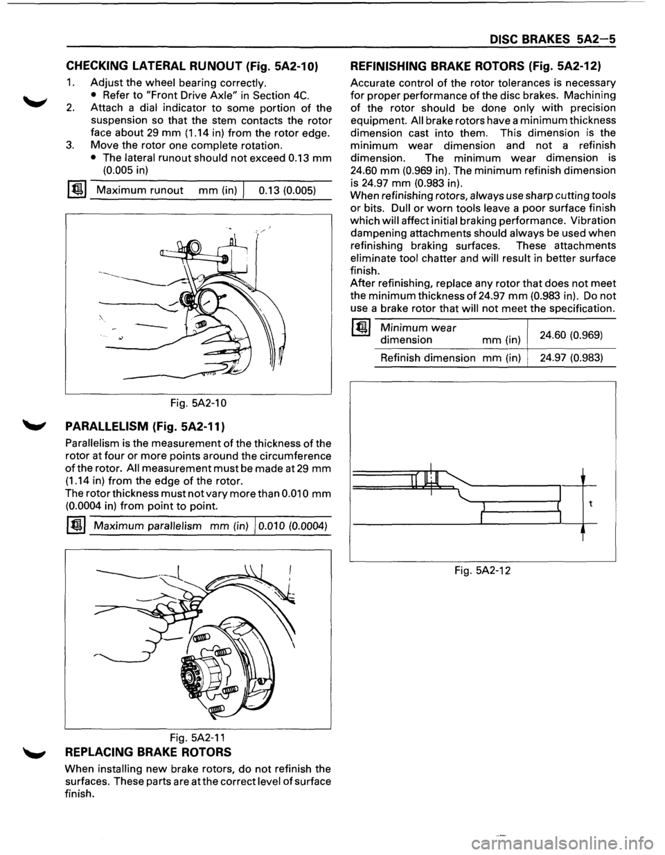
CHECKING LATERAL RUNOUT (Fig. 5A2-10)
1. Adjust the wheel bearing correctly.
•
Refer to "Front Drive Axle" in Section 4C.
2. Attach a dial indicator to some portion of the
suspension so that the stem contacts the
rotor
face about 29 mm (1.14 in) from the rotor edge.
3. Move the rotor one complete rotation.
• The lateral runout should not exceed 0.13 mm
(0.005 in)
~~~ Maximum runout mm (in) I 0.13 (0.005)
Fig. 5A2-1 0
'-' PARALLELISM (Fig. 5A2-11)
Parallelism is the measurement of the thickness of the
rotor at
four or more points around the circumference
of the rotor. All measurement must be made at 29 mm
(1.14 in) from the edge of the rotor.
The
rotor thickness must not vary more than 0.010 mm
(0.0004 in) from point to point.
~~~ Maximum parallelism mm (in) I 0.010 (0.0004)
----------1 '-----...
Fig. 5A2-11
'-' REPLACING BRAKE ROTORS
When installing new brake rotors, do not refinish the
surfaces. These parts are
atthe correct level of surface
finish.
DISC BRAKES 5A2-5
REFINISHING BRAKE ROTORS (Fig. 5A2-12)
Accurate control of the rotor tolerances is necessary
for proper performance ofthe disc brakes. Machining
of the rotor should be done only with precision
equipment.
All brake rotors have a minimum thickness
dimension cast into them. This dimension
is the
minimum wear dimension and not a refinish
dimension. The
minimum wear dimension is
24.60 mm (0.969 in). The minimum refinish dimension
is 24.97
mm (0.983 in).
When refinishing rotors,
always use sharp cutting tools
or bits. Dull or worn tools leave a poor surface finish
which
will affect initial braking performance. Vibration
dampening attachments
should always be used when
refinishing braking surfaces. These attachments
eliminate tool chatter and will result in better surface
finish.
After refinishing, replace any rotor that does not meet
the minimum thickness of 24.97 mm (0.983 in). Do not
use a brake rotor that will not meet the specification.
~~~ Minimum wear
dimension mm (in) 24.60 (0.969)
Refinish dimension
mm (in) 24.97
(0.983)
I
II lllJl I
1 t
I
Fig. 5A2-12
Page 413 of 1928
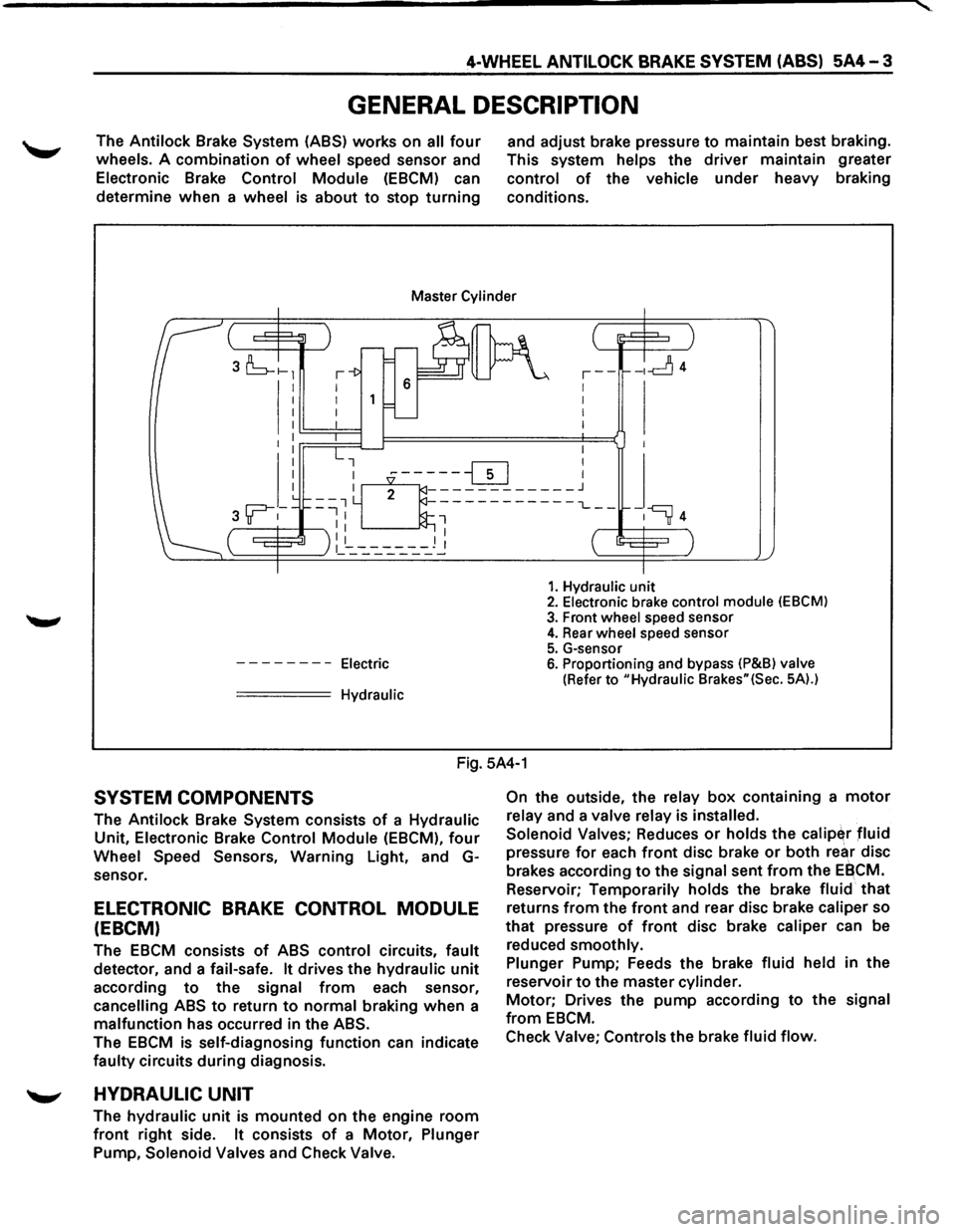
4-WHEEL ANTILOCK BRAKE SYSTEM (ABS) 5A4-3
GENERAL DESCRIPTION
The Antilock Brake System (ASS) works on all four
wheels. A combination of wheel speed sensor and
Electronic Brake Control Module (EBCM) can
determine
when a wheel is about to stop turning
and adjust brake pressure to maintain best braking.
This system
helps the driver maintain greater
control of the vehicle under heavy braking
conditions.
Master Cylinder
I I I I
--------Electric
===== Hydraulic
,--1 I
I
I
-ld4
1. Hydraulic unit 2. Electronic brake control module (EBCM)
3. Front wheel speed sensor 4. Rear wheel speed sensor
5. G-sensor 6. Proportioning and bypass (P&Bl valve
(Refer to "Hydraulic Brakes"(Sec. 5A).)
Fig. 5A4-1
SYSTEM COMPONENTS
The Antilock Brake System consists of a Hydraulic
Unit, Electronic Brake Control Module (EBCM), four
Wheel Speed Sensors, Warning Light, and G
sensor.
ELECTRONIC BRAKE CONTROL MODULE
(EBCM)
The EBCM consists of ABS control circuits, fault
detector, and a fail-safe. It drives the hydraulic unit
according to the signal from each sensor,
cancelling ABS to return to normal braking when a
malfunction has occurred in the ABS.
The EBCM is self-diagnosing function can indicate
faulty circuits during diagnosis.
'--" HYDRAULIC UNIT
The hydraulic unit is mounted on the engine room
front right side. It consists of a Motor, Plunger
Pump, Solenoid Valves and Check Valve. On
the
outside, the relay box containing a motor
relay and a valve relay is installed.
Solenoid Valves;
Reduces or holds the calip~r fluid
pressure for each front disc brake or both rear disc
brakes according
to the signal sent from the EBCM.
Reservoir;
Temporarily holds the brake fluid that
returns from the front and rear disc brake caliper so
that pressure of front disc brake caliper can be
reduced
smoothly.
Plunger
Pump; Feeds the brake fluid held in the
reservoir
to the master cylinder.
Motor; Drives the pump according to the signal
from EBCM.
Check
Valve; Controls the brake fluid flow.
Page 875 of 1928
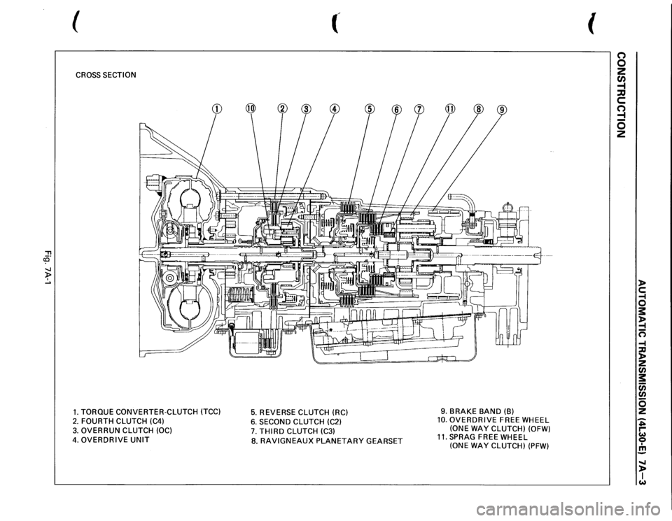
(
f
CROSS
SECTION
"'T1 ce· ~ .....
1. TORQUE CONVERTER-CLUTCH (TCC)
5.
REVERSE
CLUTCH (RC)
2.
FOURTH CLUTCH (C4)
6.
SECOND
CLUTCH (C2)
3.
OVERRUN CLUTCH
(OC)
7.
THIRD
CLUTCH (C3)
4. OVERDRIVE
UNIT
8.
RAVIGNEAUX
PLANETARY
GEARSET
9.
BRAKE
BAND (B)
10.
OVERDRIVE
FREE WHEEL
(ONE
WAY
CLUTCH) (OFW)
11.
SPRAG
FREE WHEEL
(ONE WAY
CLUTCH)
(PFW)
(
(') 0 2 CJ) -1 ::D c (') ::! 0 2
)> c: -f 0 s: )> -f n -f ::D )> 2 en s: c;; en s 2 -;; ,... w 0 I m -...... )> I w
Page 884 of 1928
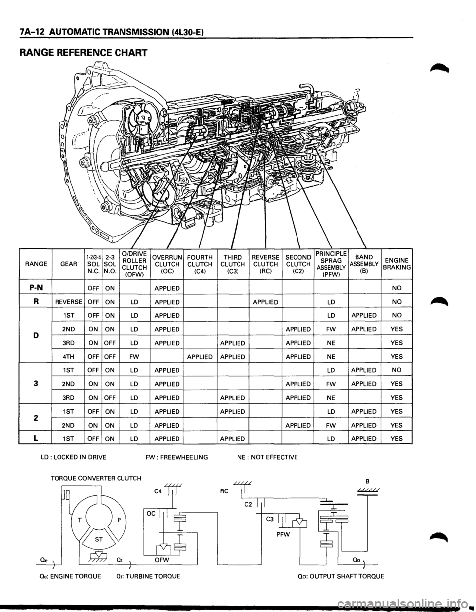
7A-12 AUTOMATIC TRANSMISSION (4L30-E)
RANGE REFERENCE CHART
1-2/3-4 2-3 0/DRIVE OVERRUN FOURTH THIRD REVERSE SECOND BAND ROLLER ENGINE RANGE
GEAR SOL
SOL
CLUTCH CLUTCH
CLUTCH CLUTCH CLUTCH CLUTCH MBLY BRAKING N_c. N.O.
(OFW) (OCl
(C4)
(C3) (RC)
(C2) (B)
P-N OFF
ON APPLIED NO
R REVERSE OFF
ON LD APPLIED APPLIED LD NO
1ST OFF
ON LD APPLIED LD APPLIED NO
2ND ON ON LD APPLIED APPLIED FW APPLIED YES D 3RD ON
OFF LD APPLIED APPLIED APPLIED NE YES
4TH OFF OFF FW APPLIED APPLIED APPLIED NE YES
1ST OFF ON
LD APPLIED LD APPLIED NO
3 2ND ON ON LD APPLIED APPLIED FW APPLIED
YES
3RD ON OFF LD APPLIED APPLIED APPLIED NE YES
1ST OFF
ON LD APPLIED APPLIED LD APPLIED YES 2 2ND ON
ON LD APPLIED APPLIED FW APPLIED YES
L 1ST OFF
ON LD APPLIED APPLIED LD APPLIED
YES
LD : LOCKED IN DRIVE FW: FREEWHEELING NE : NOT EFFECTIVE
TORQUE CONVERTER CLUTCH
B
C4lil RC 1/f ~
C2 I I
C3
PFW ~
Qe OFW
Qe: ENGINE
TORQUE Qt: TURBINE TORQUE Qo: OUTPUT SHAFT TORQUE