coolant ISUZU TROOPER 1995 Manual PDF
[x] Cancel search | Manufacturer: ISUZU, Model Year: 1995, Model line: TROOPER, Model: ISUZU TROOPER 1995Pages: 1928
Page 791 of 1928
IGNITION SYSTEM
• CHECK: Ignition timing, using a "Scan tool".
• CHECK: Ignition system; wires, plugs, electronic
ignition, etc.
ENGINE MECHANICAL
• CHECK: Perform a cylinder compression check.
See ENGINE MECHANICAL DIAGNOSIS
(SECTION 6).
• CHECK: For correct camshaft or weak valve
springs.
ADDITIONAL CHECKS
• CHECK: Manifold absolute pressure sensor.
Refer to
CHART C-10.
• CHECK: Throttle linkage for sticking or binding.
• CHECK: Park/neutral position switch circuit. See
CHART C-1A,
or use "Scan tool" and be
sure
tool indicates vehicle is in drive with
gear selector in drive or overdrive.
DRIVEABILITY AND EMISSIONS 6E2-95
• CHECK:
• CHECK:
• CHECK:
• CHECK:
• CHECK:
• CHECK:
Idle air control operation, use CHART C-
2C.
Exhaust gas recirculation valve. There
should be no exhaust gas recirculation at
idle. Refer to CHART C-7A.
Air conditioning (A/C) signal to engine
control module, "Scan tool" should
indicate A/C is being requested when
ever
A/C is selected. If problem exists
with A/C "ON," check A/C system
operation
CHART C-10.
Positive crankcase ventilation valve for
proper operation. Refer to "Positive
Crankcase Ventilation (PCV),"
Section
"6E2-C13."
For broken motor mounts.
Generator output
voltage. Repair if less
than 9 or more than 16 volts.
POOR FUEL ECONOMY
Definition: Fuel economy, as measured by an actual
road test, is noticeably lower than
expected.
Also, fuel economy is
noticeably lower than it was on this car at
one time,
as previously shown by an actual
road test.
PRELIMINARY CHECKS
• Perform the careful visual checks as described at
start
of "Symptoms," Section "6E2-B."
• Visually (physically)
check: Vacuum hoses for
splits, kinks, and proper connections as shown on
"Vehicle Emission Control Information" label.
• Check
owner's driving habits.
Is A/C "ON" full time (Defroster mode "ON")?
Are tires at correct pressure?
Are
excessively heavy loads being carried?
Is acceleration too much, too often?
• Check air cleaner filter for dirty or being plugged.
IGNITION SYSTEM
• CHECK: Ignition timing. Refer to "Vehicle
Emission Control Information" label.
• CHECK: Spark plugs. Remove spark plugs, check
for wet plugs, cracks, wear, improper
gap, burned electrodes, or heavy
deposits. Repair or
replace as necessary.
COOLING SYSTEM
• CHECK: Engine coolant level.
• CHECK: Engine thermostat for faulty part (always
open) or for wrong heat range. Refer to
ENGINE COOLING (SECTION 68).
ENGINE MECHANICAL
• CHECK: Compression. See ENGINE MECHANICAL
DIAGNOSIS
(SECTION 6A).
ADDITION CHECKS
• CHECK:
• CHECK:
• CHECK:
• CHECK:
• CHECK:
TCC operation (A/T). Use CHART C-8. A
"Scan tool" should indicate a revolution
per minute drop, when the TCC is
commanded
"ON".
For exhaust system restriction.
For proper
calibration of speedometer.
Induction system and crankcase for air
leaks.
Fuel
injectors are correct for the vehicle.
Page 792 of 1928
6E2-96 DRIVEABILITY AND EMISSIONS
EXCESSIVE EXHAUST EMISSIONS OR ODORS
Definition: Vehicle fails an emission test. Vehicle has
excessive
"rotten egg" smell. Excessive
odors
do not necessarily indicate
excessive emissions.
PRELIMINARY CHECKS
• Perform on-board diagnostic system check.
• IF EMISSION TEST shows excessive CO and
hydrocarbon check items which cause car to run
RICH (Long Term Fuel Trim less than 118), refer to
"Diagnostic Aids" on facing page of diagnostic
trouble code (DTC) 45.
• If EMISSION TEST shows excessive NOx, check
items which cause car
to run lean or too hot.
COOLING SYSTEM
• If the "Scan tool" indicates a very high engine
coolant temperature and the system is running
lean:
CHECK: Engine coolant level
CHECK: Engine thermostat for faulty part
(always open) or for wrong heat range. Refer
to
ENGINE COOLING (SECTION 68).
CHECK: Cooling fan operation.
FUEL SYSTEM
• NOTICE: If the system is running rich (L.T. Fuel
Trim near 118), refer to "Diagnostic Aids"
on facing page
of DTC 45.
-
If the system is running lean (L.T. Fuel
Trim near 142) refer to "Diagnostic
Aids" on facing page of DTC 44.
• CHECK: For properly installed fuel cap.
• CHECK: Fuel pressure. Use CHART A-7.
• CHECK: Canister for fuel loading. Refer to
"Evaporative Emission Control System,"
Section
"6E2-C3."
IGNITION SYSTEM
• CHECK: Ignition timing. Refer to "Vehicle
Emission Control Information" label.
• CHECK: Spark plugs, plug wires, and ignition
components. Refer to
ENGINE
ELECTRICAL (SECTION 6D).
ADDITIONAL CHECKS
• CHECK: For vacuum leaks.
• CHECK: Exhaust gas recirculation valve for not
opening. Use CHART C-7.
• CHECK: For lead contamination of three way
catalytic converter (look for the removal
of fuel filler neck restrictor).
• CHECK: Carbon build-up. Remove carbon with
top engine cleaner. Follow instructions
on can.
• CHECK: PCV valve for being plugged, stuck or
blocked PCV hose or fuel in the
crankcase.
BACKFIRE
Definition: Fuel ignites in intake manifold, or in
exhaust system, making
loud popping
noise.
PRELIMINARY CHECKS
• Perform the careful visual/physical checks as
described at start of "Symptoms," Section "6E2-
B."
IGNITION SYSTEM
• CHECK: Proper ignition coil output voltage with
spark tester J26792 or equivalent (ST-
125).
• CHECK: Spark plugs. Remove spark plugs, check
for
wet plugs, cracks, wear, improper
gap, burned
electrodes, or heavy
deposits. Repair
or replace as necessary.
• CHECK: Spark plug wires for crossfire, also
inspect electronic ignition, spark plug
wires, and proper routing of plug wires.
• CHECK: Ignition timing. Refer to "Vehicle
Emission Control Information" label.
• CHECK: If an intermittent condition exists in the
ignition system, see
"Ignition System/
IGNITION CONTROL," Section "6E2-C4"
or ENGINE ELECTRICAL (SECTION 6D).
ENGINE MECHANICAL
• CHECK: Compression- Look for sticking or leaking
valves.
• CHECK: Valve timing, refer to ENGINE
MECHANICAL DIAGNOSIS (SECTION
6A).
• CHECK: Intake and exhaust manifold passages for
casting
flash.
FUEL SYSTEM
• CHECK: Perform fuel system diagnosis check, see
CHART A-7.
Page 796 of 1928
6E2-100 DRIVEABILITY AND EMISSIONS
SECTION C1
ENGINE CONTROL MODULE (ECM) & SENSORS
CONTENTS
General Description ...................... 6E2-1 00
Engine Control Module (ECM) .............. 6E2-100
Engine Control Module (ECM) Function ....... 6E2-1 00
Information Sensors ..................... 6E2-1 01
Engine Coolant Temperature (ECT) Sensor ... 6E2-101
Intake Air Temperature (IAT) Sensor ........ 6E2-101
Heated Oxygen Sensor (H02S) ........... 6E2-101
Throttle Position
(TP) Sensor ............. 6E2-102
Manifold Absolute Pressure (MAP) Sensor ... 6E2-102
Vehicle Speed Sensor (VSS) ............. 6E2-102
Knock Sensor (KS) (DOHC ONLY) .......... 6E2-102
Air Conditioning (A/C) Request Signal ...... 6E2-1 02
Power Steering Pressure (PSP) Switch ...... 6E2-1 02
Park/Neutral Position (PNP) Switch
(Auto only)
........................ 6E2-1 03 Diagnosis ............................. 6E2-1 03
Engine Control Module (ECM) .............. 6E2-1 03
Electrically Erasable Programmable Read
Only Memory ........................ 6E2-1 03
Engine Control Module (ECM) Inputs ....... 6E2-103
Engine Coolant Temperature (ECT) Sensor ... 6E2-1 04
Intake Air Temperature (IAT) Sensor ........ 6E2-1 04
Heated Oxygen Sensor
(H02S) ........... 6E2-1 04
Throttle Position
(TP) Sensor ............. 6E2-1 04
Manifold Absolute Pressure (MAP) Sensor
... 6E2-1 04
Vehicle Speed Sensor (VSS) ............. 6E2-1 04
Air Conditioning (A/C) Request Signal
Power Steering Pressure
(PSP) Switch ..... .
Crankshaft Position
(CKP) Reference Signal ..
Park/Neutral Position (PNP) Switch ....... .
Knock Sensor
(KS) ................... .
On-Vehicle Service ..................... .
Engine Control Module
(ECM) ............ .
Engine Control Module
(ECM) Replacement ..
Engine Coolant Temperature (ECT) Sensor ... .
Intake Air Temperature (IAT) Sensor ........ .
Heated Oxygen Sensor
(H02S) ............ .
Throttle Position
(TP) Sensor ............. .
Manifold Absolute Pressure (MAP) Sensor
.... .
Vehicle Speed Sensor
(VSS) ............. .
Power Steering Pressure
(PSP) Switch ...... .
Park/Neutral Position
(PNP) Switch ......... .
Chart C-1A Park/Neutral Position
(PNP)
Switch Diagnosis .................... .
Chart
C-1 D Manifold Absolute Pressure (MAP)
Output Check
...................... .
Chart
C-1 E Power Steering Pressure (PSP)
Switch Diagnosis .................... .
Chart
C-1 F Heated Oxygen Sensor (H02S)
Heater Check ....................... .
6E2-104
6E2-104
6E2-104
6E2-104
6E2-104
6E2-104
6E2-104
6E2-105
6E2-105
6E2-106
6E2-106
6E2-107
6E2-107
6E2-107
6E2-107
6E2-107
6E2-108
6E2-110
6E2-112
6E2-114
GENERAL DESCRIPTION
ENGINE CONTROL MODULE (ECM)
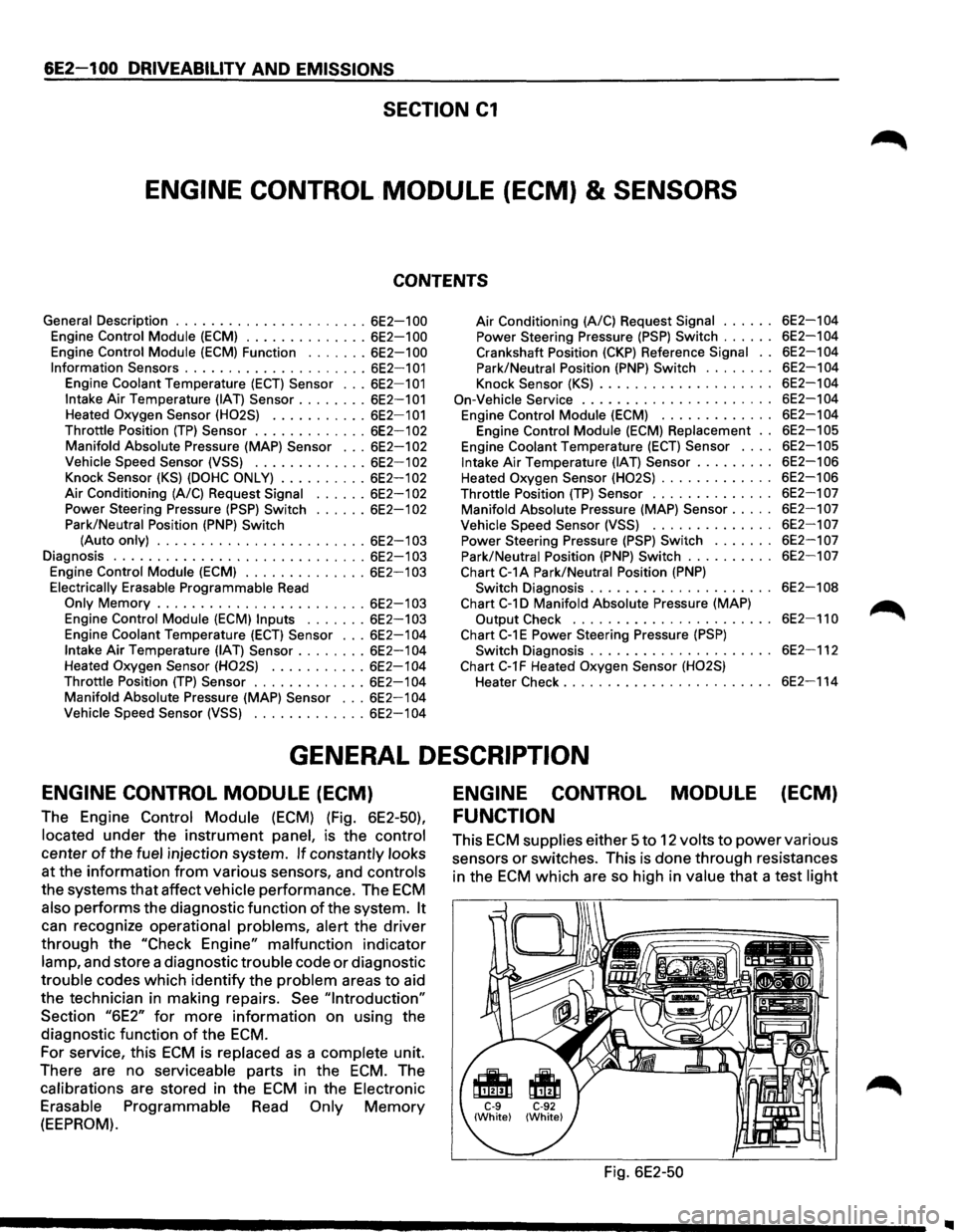
The Engine Control Module (ECM) (Fig. 6E2-50),
located under the instrument panel, is the control
center of the fuel injection system. If constantly looks
at the information from various sensors, and controls
the systems that affect vehicle performance. The ECM
also performs the diagnostic function of the system. It
can recognize operational problems, alert the driver
through the "Check Engine" malfunction indicator
lamp, and store a diagnostic trouble code or diagnostic
trouble codes which identify the problem areas to aid
the technician in making repairs.
See "Introduction"
Section "6E2" for more information on using the
diagnostic function
of the ECM.
For service, this ECM is replaced as a complete unit.
There are no serviceable parts in the
ECM. The
calibrations are stored in the
ECM in the Electronic
Erasable Programmable Read Only Memory
(EEPROM).
ENGINE CONTROL MODULE (ECM)
FUNCTION
This ECM supplies either 5 to 12 volts to power various
sensors
or switches. This is done through resistances
in the
ECM which are so high in value that a test light
Fig. 6E2-50
Page 797 of 1928
will not light when connected to the circuit. In some
cases, even an ordinary shop voltmeter
will not give an
accurate reading because its resistance is
too low.
Therefore, a 10 megohms input impedance digital
voltmeter is required to assure accurate voltage
readings.
The Engine
Control Module (ECM) controls output
circuits such as the fuel injectors, idle air control valve,
air conditioning clutch relay, etc. by controlling the
ground circuit through transistors
or a device called a
"quad-driver".
INFORMATION SENSORS
Engine Coolant Temperature (ECT) Sensor
(Fig. 6E2-51)
The Engine Coolant Temperature (ECT) Sensor is a
thermistor
(a resistor which changes value based on
temperature) mounted in the engine coolant stream.
Low ECT produces a high resistance (1 00,000 ohms at
-40.C/-40.F) while high temperature causes low
resistance (70 ohms at 130.C/266.F).
The ECM supplies a 5-volts signal to the ECT sensor
through a resistor in the
ECM and measures the
voltage. The voltage
will be high when the engine is
cold, and low when the engine is hot.
By measuring the voltage, the
ECM knows the ETC.
ECT affects most systems the ECM controls.
A failure in the
ECT sensor circuit should set a
Diagnostic Trouble Code
(DTC) 14. Remember, these
DTC(s) indicate a failure in the
ETC circuit, so proper
use
of the chart will lead to either repairing a wiring
problem or replacing the sensor, to properly repair a
problem.
1. Engine coolant temperature sensor
2. Harness connector to ECM
3. Locking tab
Fig. 6E2-51
Intake Air Temperature (IAT) Sensor
The Intake Air Temperature (IAT) sensor is a
thermistor, a resistor which changes
value based on
the temperature
of air entering the engine. Low
temperature produces a high resistance
(1 00,000
ohms at -4o·c/-40.F), while high temperature causes
low resistance (70 ohms at 130.C/266.F).
The ECM supplies a 5-volts signal to the sensor through
a resistor in the
ECM and measures the voltage. The
voltage
will be high when the intake air is cold, and low
DRIVEABILITV AND EMISSIONS 6E2-1 01
when the air is hot. By measuring the voltage, the ECM
knows the lAT.
The IAT sensor is also used to control spark timing and
delays exhaust gas recirculation when intake air is
cold.
A failure in the IAT sensor circuit should set a DTC 23.
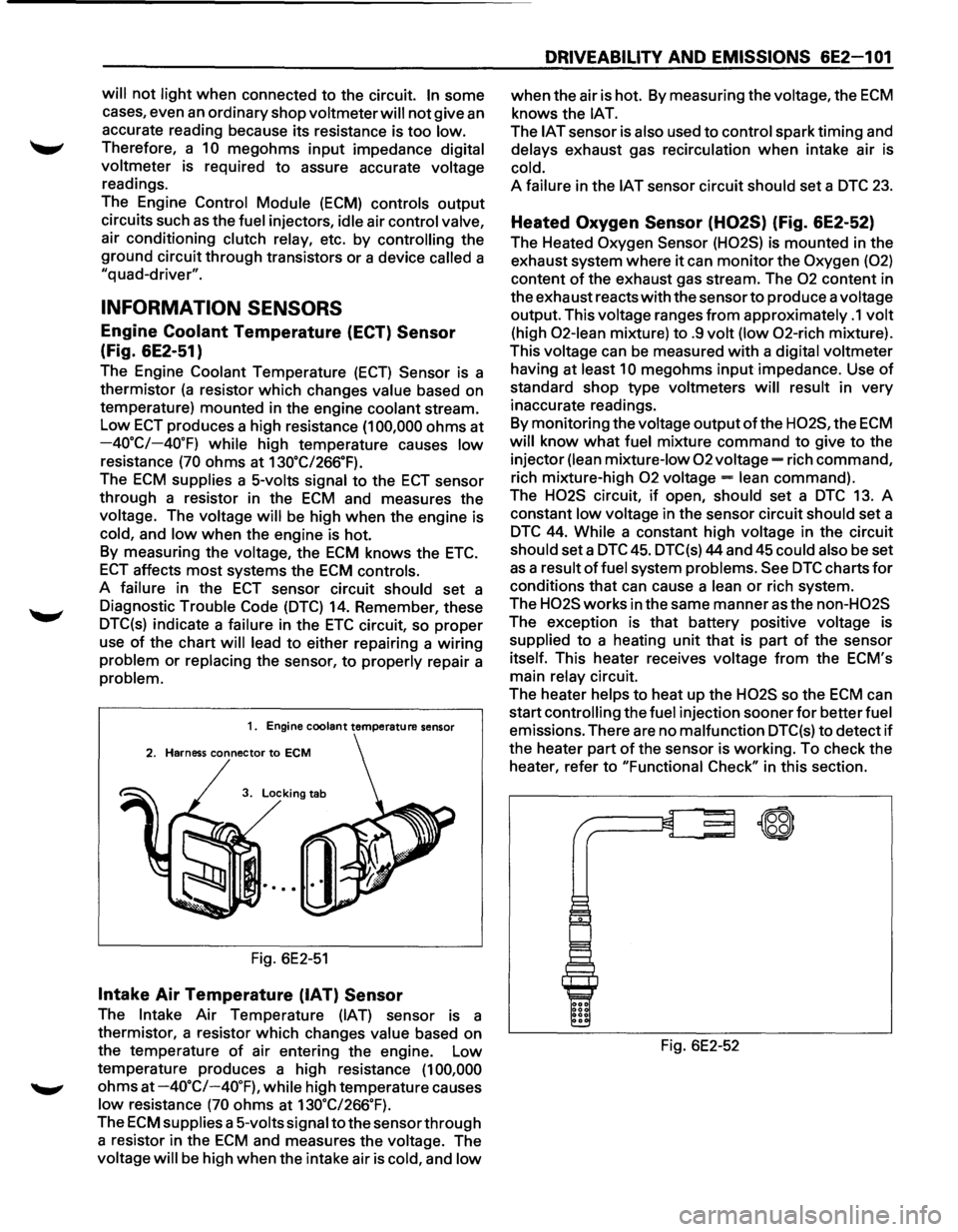
Heated Oxygen Sensor (H02S) (Fig. 6E2-52)
The Heated Oxygen Sensor (H02S) is mounted in the
exhaust system where
it can monitor the Oxygen (02)
content of the exhaust gas stream. The 02 content in
the exhaust reacts
with the sensor to produce a voltage
output. This voltage ranges
from approximately .1 volt
(high 02-lean mixture) to .9 volt (low 02-rich mixture).
This voltage can
be measured with a digital voltmeter
having at
least 10 megohms input impedance. Use of
standard shop type voltmeters will result in very
inaccurate readings.
By monitoring the voltage
output ofthe H02S, the ECM
will know what fuel mixture command to give to the
injector
(lean mixture-low 02 voltage= rich command,
rich mixture-high
02 voltage= lean command).
The
H02S circuit, if open, should set a DTC 13. A
constant
low voltage in the sensor circuit should set a
DTC 44. While a constant high voltage in the circuit
should set a DTC 45. DTC(s) 44 and 45 could also be set
as a result of fuel system problems. See DTC charts for
conditions that can cause a lean or rich system.
The
H02S works in the same manner as the non-H02S
The exception is that battery positive voltage is
supplied to a heating unit that is part of the sensor
itself. This heater receives voltage
from the ECM's
main
relay circuit.
The heater
helps to heat up the H02S so the ECM can
start
controlling the fuel injection sooner for better fuel
emissions. There are no malfunction DTC(s) to detect if
the heater part of the sensor is working. To check the
heater, refer to "Functional
Check" in this section.
Fig. 6E2-52
~
\W
Page 800 of 1928
6E2-1 04 DRIVEABILITV AND EMISSIONS
Engine Coolant Temperature (ECT) Sensor
A "Scan tool" displays engine temperature in degrees
centigrade. After engine is started, the temperature
should rise steadily to about 90°C then stabilize when
thermostat opens. If the engine has not been run for
several hours (overnight), the engine coolant
temperature (ECT) and intake air temperature (IAT)
readings should be close to each other. A fault in the
ECT sensor circuit should set a diagnostic trouble code
(DTC) 14. The DTC charts also contain a chart to check
for sensor resistance values relative to temperature.
Intake Air Temperature (IAT) Sensor
A "Scan tool" displays temperature of the air entering
the engine and
should read close to ambient air
temperature when engine
is cold, and rise as under
hood temperature increases.
If the engine has not
been run for several hours (overnight), the IAT sensor
temperature and
ECT readings should be close to each
other. A
failure in the IAT sensor circuit should set a
DTC 23. The DTC charts also contain a chart to check
for sensor resistance values relative to temperature.
Heated Oxygen Sensor (H02S)
The "Scan tool" has several positions that will indicate
the state
of the exhaust gases, Oxygen voltage,
integrator, and block learn. See "Scan tool" position
information in
"Introduction", "Driveability and
Emission," in this section.
A
problem in the oxygen sensor circuit, or fuel system,
should set a DTC 13 (open circuit), DTC 44 (lean
indication)/DTC 45 (rich indication). Refer to
applicable chart, if any of these DTC(s) were stored in
memory.
Throttle Position (TP) Sensor
A "Scan tool" displays throttle position in volts. On 3.2L
engine, Throttle position
(TP) sensor voltage should
read below 0.85 volts, with throttle closed and ignition
"ON", or at idle. Voltage should increase at a steady
rate
as throttle is moved toward wide open throttle.
The Engine
Control Module (ECM) has the ability to
auto-zero the TP sensor voltage if it is below about 0.85
volts. This means that any voltage less than 0.85 volts
will
be determined by the ECM to be 0% throttle.
Some
"Scan tools" have the ability to read the throttle
angle and should read 0%, when the throttle is closed.
A failure in the TP sensor or circuit should set a DTC 21.
Manifold Absolute Pressure (MAP) Sensor
"Scan tool" displays manifold pressure in volts. Low
pressure (high vacuum) reads a
low voltage, while a
high pressure
(low vacuum) reads a high voltage. A
failure in the Manifold Absolute Pressure (MAP) sensor
circuit
should set a DTC 33 and using the chart will find
the cause
of the problem. A DTC 33 may be set if a
rough or unstable
idle exists. CHART C-1 D can also be
used
to check MAP sensor.
Vehicle Speed Sensor (VSS)
A "Scan tool" reading should closely match with
speedometer reading with drive wheels turning. A
failure in the vehicle speed sensor circuit should set a
DTC 24.
AIR CONDITIONING (A/C) Request Signal
When air conditioning in "ON", the "Scan tool" should
indicate air conditioning "ON".
See
"Air Conditioning Compressor Clutch Control
System",
Section "6E2-C1 0" for A/C electrical system
diagnosis.
Power Steering Pressure (PSP) Switch
A "Scan tool" should read "OFF" normally, and "ON"
with high pressure. This reading may vary with
different "Scan tools". Refer to CHART C-1 E for power
steering pressure switch diagnosis.
Crankshaft Position (CKP) Reference Signal
The ignition control module sends a signal to the ECM,
which is used to calculate proper spark advance and
fuel delivery. A "Scan tool" will read this signal and is
displayed in revolution per minute.
See "Electronic
Ignition System",
Section "6E2-C-4" for more
information on the ignition system (ignition control).
Park/Neutral Position (PNP) Switch
A "Scan tool" should read park/neutral position when
in park, or neutral, and R-D, L, when in drive or
overdrive. This reading may vary with different makes
of tools. Refer to CHART C-1 A for park/neutral position
switch diagnosis.
Knock Sensor (KS)
A "Scan tool" will indicate when the knock sensor
module signals the ECM that knock is present. See
"Knock
Sensor System," Section "6E2-C5" for further
information on the knock sensor system.
ON-VEHICLE SERVICE
ENGINE CONTROL MODULE (ECM)
The ECM is programmed from the factory and has no replaceable calibration chip.
•
Page 801 of 1928
wcAUTION:
' • When replacing the production Engine Control
Module
(ECM) with a service ECM (controller),
it is important to transfer the broadcast
diagnostic
trouble code and production ECM
number to the service ECM label. Please do not
record on ECM cover. This will allow positive
identification
of ECM parts throughout the
service
life of the vehicle.
DRIVEABILITV AND EMISSIONS 6E2-1 05
\fCAUTION:
' • To prevent internal ECM damage, the ignition
must be
"OFF" when disconnecting or
reconnecting power
to ECM (for example;
battery cable, ECM pigtail, ECM fuse, jumper
cables etc.)
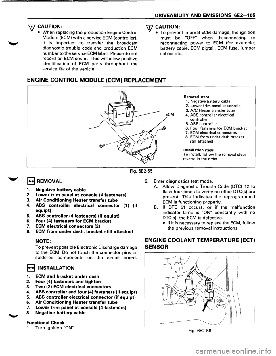
ENGINE CONTROL MODULE (ECM) REPLACEMENT
Removal steps 1. Negative battery cable 2. Lower trim panel at console
3. A/C Heater transfer tube ECM 4. ABS controller electrical
controller
5. ABS controller 6. Four fasteners for ECM bracket
7. ECM electrical connectors
8. ECM from under dash bracket still attached
Installation steps To install, follow the removal steps
reverse in the order.
Fig. 6E2-55
EJ REMOVAL
1. Negative battery cable
2. Lower trim panel at console (4 fasteners)
3. Air Conditioning Heater transfer tube
4. ABS controller electrical connector (1) (if
equipt)
5. ABS controller (4 fasteners) (if equipt)
6. Four (4) fasteners for ECM bracket
7. ECM
electrical connectors (2)
8. ECM from under dash, bracket
still attached
NOTE:
To prevent possible Electronic Discharge damage
to the ECM, Do not touch the connector pins or
soldered components on the circuit board.
I•+! INSTALLATION
1. ECM and bracket under dash
2. Four (4) fasteners and tighten
3. Two (2) ECM electrical connectors
4. ABS controller and four (4) fasteners (if equipt)
5. ABS controller electrical connector (if equipt)
6. Air Conditioning Heater transfer tube
7. Lower trim panel at console (4 fasteners)
8. Negative battery
cable
Functional
Check
1. Turn ignition "ON".
2. Enter diagnostics test mode.
A.
Allow Diagnostic Trouble Code (DTC) 12 to
flash four times to verify no other DTC(s) are
present. This indicates the reprogrammed
ECM is functioning properly.
B. If DTC 51 occurs, or if the malfunction
indicator lamp is "ON" constantly with no
DTC(s), the
ECM is defective.
• If it is necessary to replace the ECM, follow
the previous removal instructions.
ENGINE COOLANT TEMPERATURE (ECT)
SENSOR
Fig. 6E2-56
Page 802 of 1928
6E2-1 06 DRIVEABILITV AND EMISSIONS
1••1 REMOVAL
\f7 CAUTION:
Y/ Care must be taken when handling Engine
Coolant Temperature (ECT) sensor. Damage to
ECT sensor will affect proper operation of the fuel
injection system.
Preparation: • Negative battery cable.
•
Drain engine coolant system.
1. Inlet manifold assembly
• Refer to "Fuel metering system" section "6E2-
C2"
for removal procedure.
2. Electrical connector
3. ECT sensor
• Remove from rear of engine coolant transfer
tube.
I••IINSTALLATION
3. ECT sensor
• Apply sealer or equivalent to threads only.
•
Tighten the ECT sensor to the specified torque
~~~ Torque N·m (lb·ft) I 30 (22)
2. ECT sensor connector
1. Intake manifold assembly
• Refer to "Fuel metering system" section "6E2-
C2" for installation.
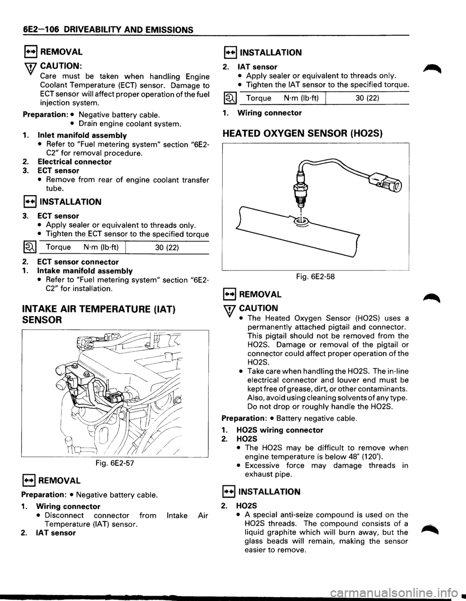
INTAKE AIR TEMPERATURE (IAT)
SENSOR
Fig. 6E2-57
1••1 REMOVAL
Preparation: • Negative battery cable.
1. Wiring connector
• Disconnect connector from Intake Air
Temperature (IAT) sensor.
2. IAT sensor
I••IINSTALLATION
2. IAT sensor
• Apply sealer or equivalent to threads only.
•
Tighten the IAT sensor to the specified torque.
~~~ Torque N·m (lb·ft) 30 (22)
1. Wiring
connector
HEATED OXYGEN SENSOR (H02S)
Fig. 6E2-58
1••1 REMOVAL
'fCAUTION
• The Heated Oxygen Sensor (H02S) uses a
permanently attached pigtail and connector.
This
pigtail should not be removed from the
H02S. Damage or removal of the pigtail or
connector
could affect proper operation of the
H02S.
•
Take care when handling the H02S. The in-line
electrical
connector and louver end must be
kept free
of grease, dirt, or other contaminants.
Also, avoid using cleaning solvents of any type.
Do not drop or roughly handle the H02S.
Preparation: • Battery negative cable.
1. H02S wiring connector
2. H02S
• The H02S may be difficult to remove when
engine temperature is
below 48• (120.).
•
Excessive force may damage threads in
exhaust pipe.
I••IINSTALLATION
2. H02S
• A special anti-seize compound is used on the
H02S threads. The compound consists of a
liquid graphite which will burn away, but the
glass beads will remain, making the sensor
easier
to remove.
•
Page 813 of 1928
MODES OF OPERATION
The Engine Control Module (ECM) uses voltage inputs
from several sensors to determine how much fuel to
give the engine. The fuel is delivered under one of
several conditions, called "modes". All the modes are
controlled by the ECM and are described below.
Starting Mode
When the ignition is first turned "ON", the ECM turns
"ON" the fuel pump relay for two seconds, and the fuel
pump builds up pressure. The ECM also checks the
Engine
Coolant Temperature (ECT) sensor and the
Throttle Position Sensor, and the determines the
proper
air/fuel ratio for starting. This ranges from 1.5:1
-36·c (-33.F) to 14.7:1, at 94•c (201.F) ECT.
The ECM controls the amount of fuel delivered in the
starting mode by changing
how long the injector is
turned
"ON" and "OFF". The is done by "Pulsing" the
injectors
for very short times.
Clear Flood Mode
If the engine floods, it may be cleared by pushing the
accelerator pedal down all the way. The ECM then will
fixed air/fuel ratio 16.5:1. The ECM holds this injector
rate
as long as the throttle stays wide open. If the
throttle position becomes less than approximately
70%, the ECM returns to the starting mode.
Run Mode
The run mode has two conditions called "Open Loop"
and "Closed Loop"
"Open Loop"
When the engine is first started, and it is above 500
Rovolution Per Minute (rpm), the system goes into
"Open Loop" operation. IN "Open Loop," the ECM
ignores the signal from the heated oxygen sensor
(H02S), and calculates the air/fuel ratio based on
inputs
from the ECT sensor and manifold absolute
pressure sensors.
The system stays in
"Open Loop" until the following
conditions are met:
1. The H02S has varying voltage output, showing
that
it is hot enough to operate properly. (This
depends on temperature.)
2. The ECT sensor is above a specified temperature.
3. A specific amount of time has elapsed after
starting the engine.
"Closed Loop"
The specific values for the above conditions vary with
different engines, and are stored in the ECM. When
these conditions are met, the system goes into
"Closed
Loop"
operation. In "Closed Loop", the ECM calculates
the air/fuel ratio (injector on-time) based on the signal
from the H02S. This allows the air/fuel ratio to stay
very close to 14.7:1.
DRIVEABILITV AND EMISSIONS 6E2-117
Acceleration Mode
The ECM responds to rapid changes in throttle position
and air
flow, and provides extra fuel.
Deceleration Mode
The ECM responds to changes in throttle position and
air
flow, and reduces the amount of fuel. When
deceleration is very fast, the ECM can cut off fuel
completely
for short periods.
Battery Positive Voltage Correction Mode
When battery positive voltage is low, the ECM can
compensate
for a weak spark delivered by the ignition
control module by:
• Increasing injector pulse width.
• Increasing the idle rpm.
• Increasing ignition dwell time.
Fuel Cutoff Mode
The fuel injectors are shut "OFF" if engine speed
"exceed" 6880 rpm (DOHC) or6800 rpm (SOHC). This is
to prevent damage to engine. When engine speed is
below 6880 rpm (DOHC) or 6800 rpm (SOHC), the fuel
injectors are again pulsed at a normal mode.
Page 816 of 1928
6E2 120 DRIVEABILITY AND EMISSIONS
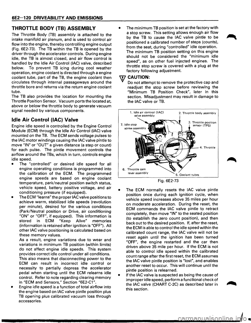
THROTTLE BODY (TB) ASSEMBLY
The Throttle Body (TB) assembly is attached to the
intake manifold air
plenum, and is used to control air
flow into the engine, thereby controlling engine output
(Fig. 6E2-73). The TB within the TB is opened by the
driver through the accelerator controls. During engine
idle, the
TB is almost closed, and air flow control is
handled by the Idle Air Control (lAC) valve, described
below. To prevent
TB icing during cool weather
operation, engine
coolant is directed through a engine
coolant tube, part
of the TB, the engine coolant then
circulates through internal passageways around the
throttle bore and returns via the return engine coolant
tube.
The
TB also provides the location for mounting the
Throttle Position
Sensor. Vacuum ports the located at,
above or
below the throttle body to generate vacuum
signal needed
by various components.
Idle Air Control (lAC) Valve
Engine idle speed is controlled by the Engine Control
Module (ECM) through the Idle Air Control (lAC) valve
mounted on the
TB. The ECM sends voltage pulses to
the lAC motor windings causing the lAC valve pintle to
move "IN" or "OUT" a given distance (a step or count)
for each pulse. The pintle movement controls the
airflow around the TBs, which in turn, controls engine
idle speed.
• The "controlled" or desired idle speed for all
engine operating conditions is programmed into
the
calibration of the ECM. The programmed
engine speeds are based on engine coolant
temperature, park/neutral position switch status,
vehicle speed, battery positive voltage, and air
conditioning pressure (if equipped).
• The ECM "learns" the proper lAC valve positions to
achieve warm, stabilized idle speeds (revolution
per minute), desired
for the various conditions
(Park/Neutral position
or Drive, air conditioning
"ON" or "OFF", if equipped). This information is
stored in
ECM "Keep Alive" memories
(information
is retained after ignition is "OFF"). All
other lAC valve positioning is calculated based on
these
memory values.
As a
result, engine variations due to wear and
variations in
minimum TB position (within limits)
do not affect engine idle speeds. This system
provides correct idle control under
all conditions.
This also means
that disconnecting power to the
ECM can result in incorrect idle control or
necessity to partially depress the accelerator
pedal
when starting until the ECM relearns idle
control. Refer to note regarding clearing
memory
in "ECM and Sensors," Section "6E2-C1 ".
•
Engine idle speed is a function of total airflow into
the engine based on
lAC valve pintle position plus
TB opening plus calibrated vacuum loss through
accessories.
• The minimum TB position is set at the factory with
a stop screw. This setting allows enough air flow
by the TB to cause the lAC valve pintle to be
positioned a calibrated
number of steps (counts),
from the seat, during "controlled" idle operation.
The
minimum TB position setting on this engine
should not be considered the
"minimum idle
speed", as on other fuel injected engines. The
throttle stop
screw is covered with a plug at the
factory
following adjustment.
U7 CAUTION:
VI Do not attempt to remove the protective cap and
readjust the stop screw before
reviewi~g t~e
"Minimum TB Position Check", later m th1s
section. Misadjustment may result in damage to
the lAC valve or TB.
Fig. 6E2-73
2. Throttle body assembly
3. Throttle position sensor (TPS)
• The ECM normally resets the lAC valve pintle
position once during each ignition cycle,
when
vehicle speed increases above 35 miles per hour
on moderate acceleration. During the reset, the
ECM commands the lAC valve pintle to retract
completely, then move
"IN" to the seated position
(to establish the zero
count position), and then
back
out to the desired position. If, after the reset,
the
ECM is able to control the idle speed within the
calibrated count range, the
lAC valve will not be
reset again until the ignition has been turned
"OFF", the engine restarted and the car then
driven above 35 mile per hour.
If the ECM is not
able to control idle speed within the calibrated
count range after the first reset, the
ECM assumes
the
lAC valve pintle position is "lost", and enables
another reset
to occur. This will continue until the
pintle position is relearned.
• If the lAC valve is suspected as being the cause of
improper idle speed, perform a functional check of
the lAC valve (CHART C-2C) as described later in
this section.
-----------------------------'
•
Page 821 of 1928
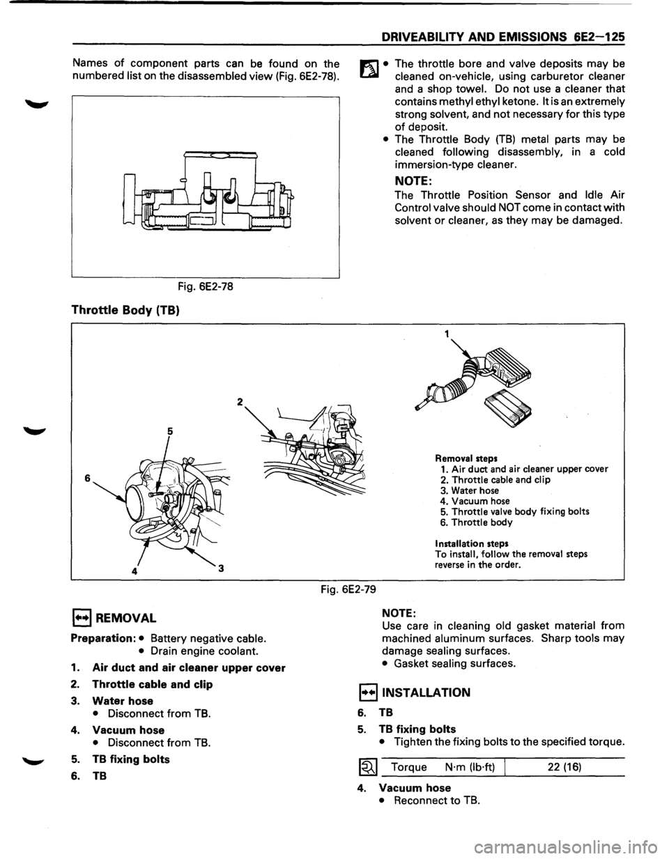
Names of component parts can be found on the
numbered
list on the disassembled view (Fig. 6E2-78).
Fig. 6E2-78
Throttle Body (TB)
5
6
2
DRIVEABILITY AND EMISSIONS 6E2-125
m • The throttle bore and valve deposits may be
t..a.l cleaned on-vehicle, using carburetor cleaner
and a shop towel. Do not use a cleaner that
contains
methyl ethyl ketone. It is an extremely
strong solvent, and
not necessary for this type
of deposit.
• The Throttle Body (TB) metal parts may be
cleaned following disassembly, in a cold
immersion-type cleaner.
NOTE:
The Throttle Position Sensor and Idle Air
Control
valve should NOT come in contact with
solvent or
cleaner, as they may be damaged.
1
Removal steps
1. Air duct and air cleaner upper cover
2.
Throttle cable and clip
3. Water hose
4. Vacuum hose
5.
Throttle valve body fixing bolts
6. Throttle body
Installation steps
To install, follow the removal steps
reverse in
the order.
Fig. 6E2-79
1••1 REMOVAL
Preparation: • Battery negative cable.
•
Drain engine coolant.
1. Air duct and air cleaner upper cover
2. Throttle cable and clip
3. Water hose
• Disconnect from TB.
4. Vacuum hose
• Disconnect from TB.
5. TB fixing bolts
6. TB
NOTE:
Use care in cleaning old gasket material from
machined
aluminum surfaces. Sharp tools may
damage
sealing surfaces.
• Gasket sealing surfaces.
I••IINSTALLATION
6. TB
5. TB fixing bolts
• Tighten the fixing bolts to the specified torque.
~~~ Torque N·m (lb·ft) 22 (16)
4. Vacuum hose
• Reconnect to TB.