ISUZU TROOPER 1995 Workshop Manual
TROOPER 1995
ISUZU
ISUZU
https://www.carmanualsonline.info/img/61/57183/w960_57183-0.png
ISUZU TROOPER 1995 Workshop Manual
Page 1507 of 1928
CHASSIS ELECTRICAL 8-317
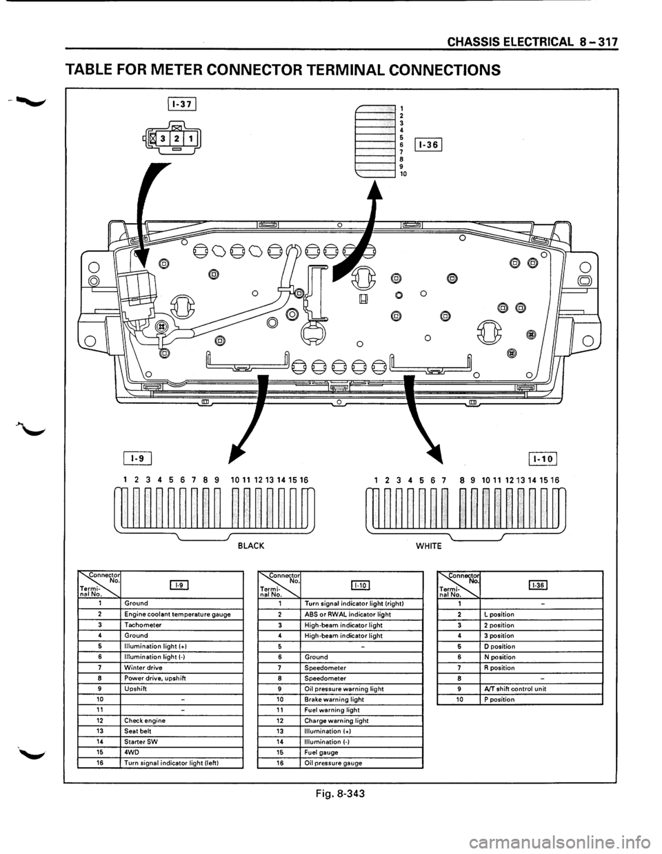
TABLE FOR METER CONNECTOR TERMINAL CONNECTIONS
~-""""""', 1----""'12 1----""'1! 6 1----l 6 [Iill
1----""'1 ~ 9 1---""'l,o
®
0 0
0
® @
0 0 ~
~m© © © © ©'--m ~~0
0 !III
1 2 3 4 5 6 7 8 9 1011 1213141516 1 2 3 4 56 7 8 9 10111213141516
w~~~~~~~~ ~~~~~~m rn~~~~~~ ~~nn~~m
~ I J BLACK WHITE
~r o. DTI -na No. ~
. IJJ:Q] -
. ~ [ill] . -. 1 Ground 1 Turn
signal indicator light (right)
1 -2 Engine coolant temperature gauge 2 ABS or RWAL indicator light 2 L
position
3 Tachometer 3 High-beam indicator light 3 2 position 4
Ground
4 High-beam
indicator light 4 3 position 6 Illumination light (+I 5 -5 D position
6 Illumination light(-) 6 Ground 6 N position 7 Winter drive 7 Speedometer 7 R position 8 Power drive, upshift 8 Speedometer 8 -9 Upshift 9 Oil pressure warning light 9 AfT shift control unit 10 -10 Brake warning light 10 P position 11 -11 Fuel warning light 12 Check engine 12 Charge warning light 13 Seat belt 13 Illumination (+) 14 StarterSW 14 Illumination (-) 15 4WD 15 Fuel gauge 16 Turn signal indicator light (left) 16 Oil pressure gauge
Fig. 8-343
Page 1513 of 1928
B INSTALLATION
To install, follow the removal steps in the reverse
order.
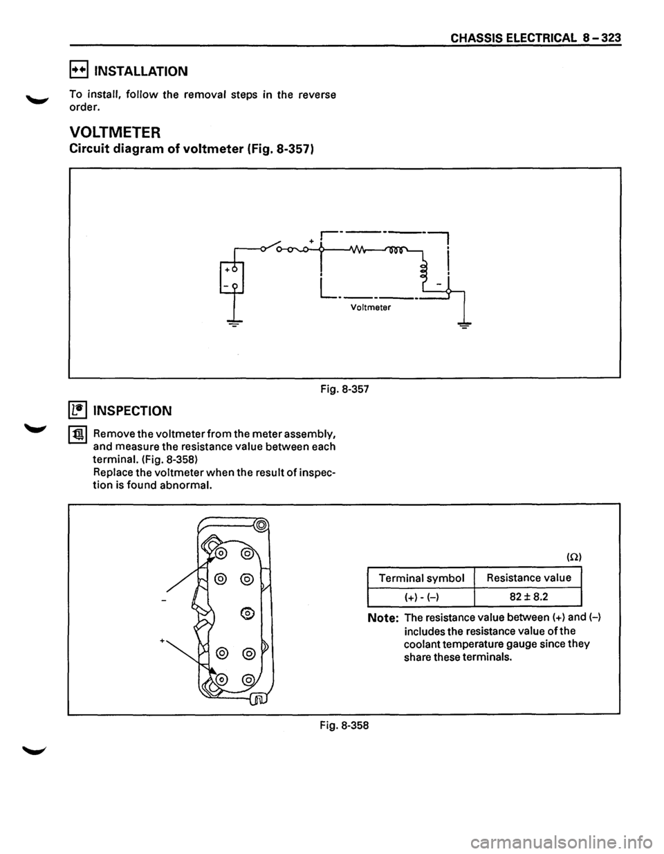
VOLTMETER
Circuit diagram of voltmeter (Fig. 8-357)
CHASSIS ELECTRICAL 8-323
Voltmeter
Fig. 8-357
~ INSPECTION
I t!!.l Remove the voltmeter from the meter assembly,
and measure the resistance value between each
terminal. (Fig. 8-358)
Replace the voltmeter when the result of inspec
tion is found
abnormal.
+
(Q)
Terminal symbol Resistance value
(+)-(-) 82 ± 8.2
Note: The resistance value between (+) and H
includes the resistance value ofthe
coolant temperature gauge since they
share these
terminals.
Fig. 8-358
Page 1514 of 1928
8-324 CHASSIS ELECTRICAL
B REMOVAL (FIG. 8-359)
Preparation: Disconnect the battery ground cable.
Voltmeter
Fig. 8-359
1. Meter assembly
2. Meter cluster glass
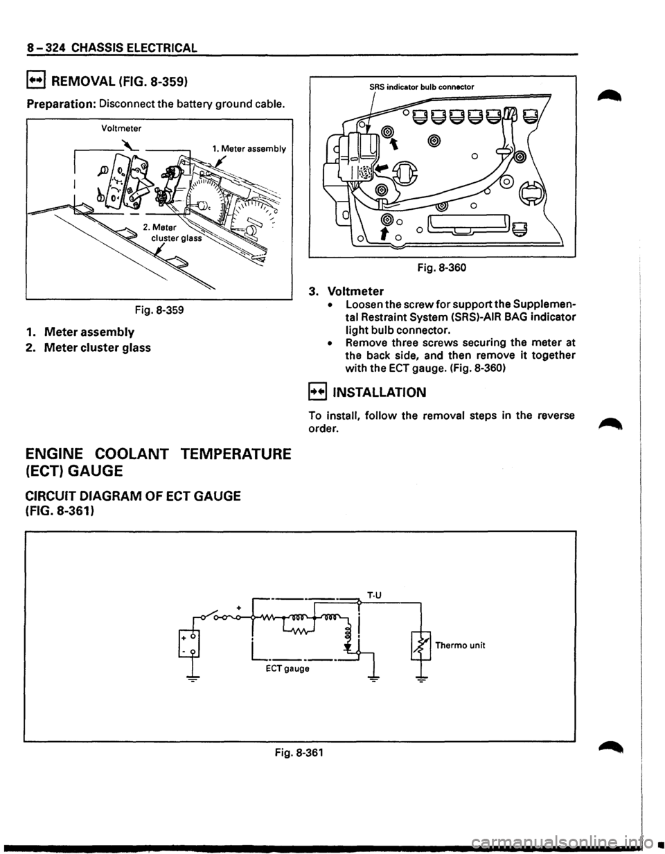
ENGINE COOLANT TEMPERATURE
(ECT) GAUGE
CIRCUIT DIAGRAM OF ECT GAUGE
(FIG. 8-361)
SRS indicator bulb connector
Fig. 8-360
3. Voltmeter
• Loosen the screw for support the Supplemen
tal
Restraint System (SRS)-AIR BAG indicator
light bulb connector.
• Remove three screws securing the meter at
the back side, and then remove
it together
with the
ECT gauge. (Fig. 8-360)
B INSTALLATION
To install, follow the removal steps in the reverse ....-...
order. ,........
Thermo unit
ECTgauge
Fig. 8-361
•
Page 1515 of 1928
~ INSPECTION
131 Remove the engine coolant temperature (ECT)
gauge from the meter assembly, and measure
the resistance value between each terminal.
T·U
+
Fig. 8-362
E) REMOVAL AND INSTALLATION
1••1 Refer to the removal and installation steps the
voltmeter.
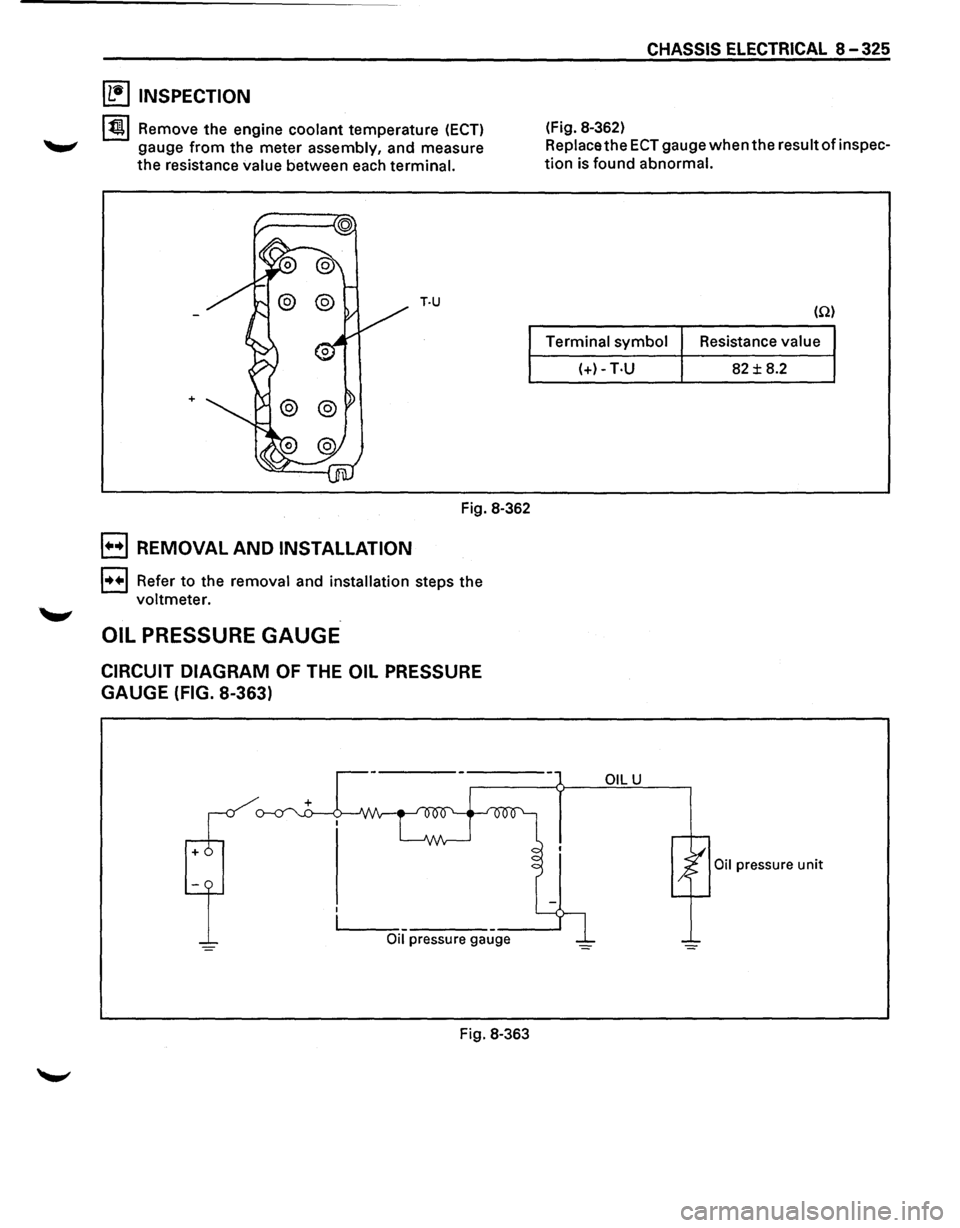
OIL PRESSURE GAUGE
CIRCUIT DIAGRAM OF THE OIL PRESSURE
GAUGE (FIG. 8-363)
CHASSIS ELECTRICAL 8 -325
(Fig. 8-362)
Replace the
ECT gauge when the result of inspec
tion is found abnormal.
(Q)
Terminal symbol Resistance
value
(+)-T·U 82 ± 8.2
OILU
Oil pressure unit
,______ _ __ ___.
Oil pressure gauge
Fig. 8-363
Page 1532 of 1928
8-340 CHASSIS ELECTRICAL
HEATER AND AIR CONDITIONING
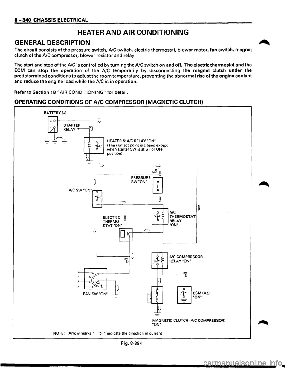
GENERAL DESCRIPTION
The circuit consists of the pressure switch, NC switch, electric thermostat, blower motor, fan switch, magnet
clutch of the NC compressor, blower resistor and relay.
The start and stop of the NC is controlled by turning the NC switch on and off. The electric thermostat and the
ECM can stop the operation of the NC temporarily by disconnecting the magnet clutch under the
predetermined conditions
to adjust the room temperature, preventing the abnormal rise of the engine coolant
and reduce the engine load while the NC is in operation.
Refer
to Section 18 "AIR CONDITIONING" for detail.
OPERATING CONDITIONS OF A/C COMPRESSOR (MAGNETIC CLUTCH)
BATIERY(+)
--
~
A/C SW "ON"
~
HEATER & A/C RELAY "ON"
(The contact point is closed except
when starter SW is at ST or OFF position)
(S =:>
¢:!]
PRESSURE D
SW"ON"
¢:::l
~ FAN SW"ON"
u A/C THERMOSTAT
RELAY
"ON"
A/C COMPRESSOR
RELAY"ON"
ECM IA2l "ON"
MAGNETIC
CLUTCH lAIC COMPRESSOR)
"ON"
NOTE:
Arrow marks" =:> " indicate the direction of current
Fig. 8-394
~
1111