power steering ISUZU TROOPER 1995 Manual PDF
[x] Cancel search | Manufacturer: ISUZU, Model Year: 1995, Model line: TROOPER, Model: ISUZU TROOPER 1995Pages: 1928
Page 1219 of 1928
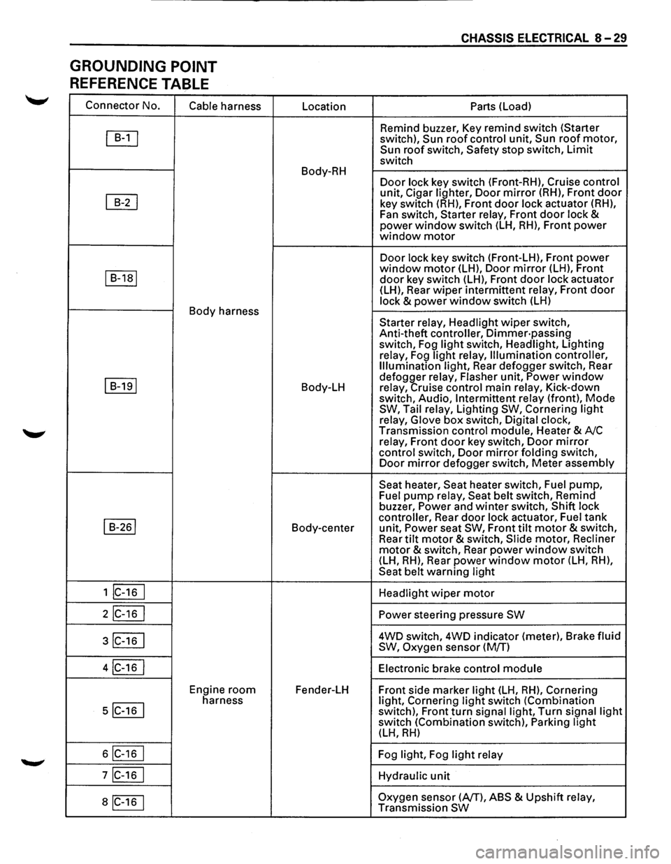
GROUNDING POINT
REFERENCE TABLE
Connector No.
Cable harness
~
~
I B-1a1
Body harness
I B-191
I B-261
1 lc-16 I
2IC-16 I
3IC-16 I
4IC-16 I
Engine room
5IC-16 I
harness
6IC-16 I
7IC-16 I
aiC-16 1
Location
Body-RH
Body-LH
Body-center
Fender-LH
CHASSIS ElECTRICAL 8-29
Parts (Load)
Remind buzzer, Key remind switch (Starter
switch),
Sun roof control unit, Sun roof motor, Sun roof switch, Safety stop switch, Limit
switch
Door lock key switch (Front-RH), Cruise control
unit, Cigar lighter, Door mirror (RH), Front door
key switch (RH), Front door lock actuator (RH),
Fan switch, Starter relay, Front
door lock & power window switch (LH, RH), Front power window motor
Door lock key switch (Front-LH), Front power window motor (LH), Door mirror (LH), Front
door key switch (LH), Front door lock actuator
(LH), Rear wiper intermittent relay, Front door
lock & power window switch (LH)
Starter relay, Headlight
wiper switch,
Anti-theft controller,
Dimmer·passing switch, Fog light switch, Headlight, Lighting
relay, Fog
light relay, Illumination controller,
Illumination light, Rear defogger switch, Rear
defogger relay, Flasher unit,
Power window relay, Cruise control main relay, Kick-down
switch, Audio, Intermittent relay (front), Mode SW, Tail relay, Lighting SW, Cornering light
relay, Glove box switch, Digital clock,
Transmission control module, Heater & A/C
relay, Front
door key switch, Door mirror
control switch, Door mirror folding switch,
Door mirror defogger switch, Meter assembly
Seat heater, Seat heater switch, Fuel pump, Fuel pump relay, Seat belt switch, Remind
buzzer, Power and winter switch, Shift lock
controller, Rear
door lock actuator, Fuel tank
unit, Power seat SW, Front tilt motor & switch,
Rear tilt motor & switch, Slide motor, Recliner
motor & switch, Rear power window switch
(LH, RH), Rear power window motor (LH, RH),
Seat belt warning light
Headlight
wiper motor
Power steering pressure SW
4WD switch, 4WD indicator (meter), Brake fluid
SW, Oxygen sensor (M/T)
Electronic brake control
module
Front side marker light (LH, RH), Cornering
light, Cornering light switch (Combination
switch), Front turn signal light, Turn signal light switch (Combination switch), Parking light (LH, RH)
Fog light, Fog light relay
Hydraulic
unit
Oxygen sensor (AfT), ABS & Upshift relay,
Transmission SW
Page 1234 of 1928
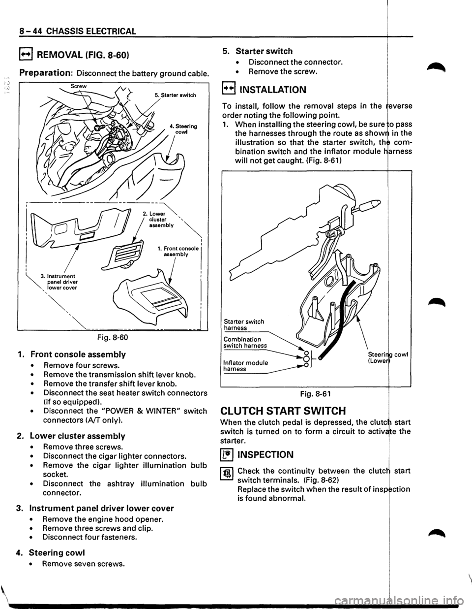
8-44 CHASSIS ELECTRICAL
B REMOVAL (FIG. 8-60)
Preparation: Disconnect the battery ground cable.
5. Starter switch
Fig. 8-60
1. Front console assembly
• Remove four screws.
• Remove the transmission shift lever knob.
• Remove the transfer shift lever knob.
• Disconnect the seat heater switch connectors
(If so equipped).
• Disconnect the "POWER & WINTER" switch
connectors
(A/T only).
2. Lower cluster assembly
• Remove three screws.
• Disconnect the cigar lighter connectors.
• Remove the cigar lighter illumination bulb
socket.
• Disconnect the ashtray illumination bulb
connector.
3. Instrument panel driver lower cover
• Remove the engine hood opener.
• Remove three screws and clip.
• Disconnect four fasteners.
4. Steering cowl
• Remove seven screws .
5. Starter switch
• Disconnect the connector.
• Remove the screw.
B INSTALLATION
To install, follow the removal steps in the everse
order noting the
following point.
1. When installing the steering cowl, be sure o pass
the harnesses through the route as
show in the
illustration so that the starter switch, th com
bination switch and the inflator
module
will not get caught. (Fig. 8-61)
Starter switch
harness
Fig. 8-61
CLUTCH START SWITCH
cowl
When the clutch pedal is depressed, the clute start
switch is turned on
to form a circuit to activ e the
starter.
~ INSPECTION
1 til!. I Check the continuity between the clute start
switch terminals. (Fig. 8-62)
Replace the switch when the result
of insp ction
is found abnormal.
'
Page 1239 of 1928
!! (Q
(
FUEL INJECTOR
No.1
/
FUEL INJECTOR
No.5
FUEL INJECTOR
No.3
I
\/.
ICM
CPOWERl
_/
E-27
cp
I
CRANKSHAFT
~
POSITION SENSOR
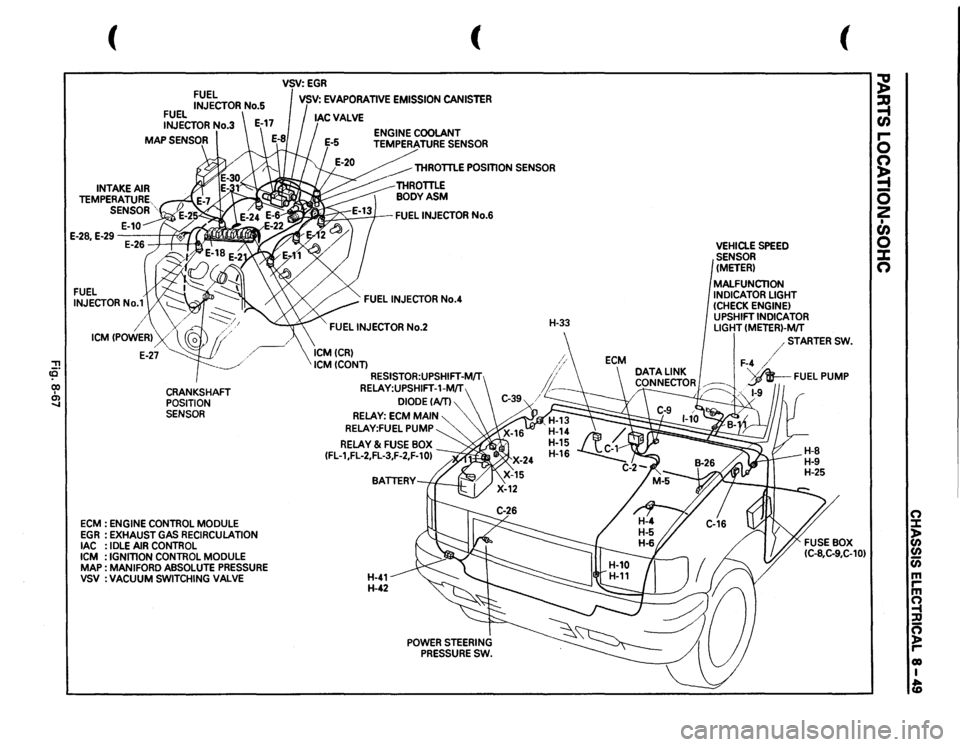
ECM
: ENGINE
CONTROL
MODULE
EGR
:EXHAUST
GAS
RECIRCULATION
lAC
: IDLE
AIR
CONTROL
ICM
: IGNmON
CONTROL
MODULE
MAP
: MAN
I FORD
ABSOLUTE
PRESSURE
VSV
:VACUUM
SWITCHING
VALVE
(
VSV:EGR I VSV:
EVAPORATIVE
EMISSION
CANISTER
THROTTLE
POSmON
SENSOR
~FUEL
INJECTOR
No.6
FUEL
INJECTOR
No.4
FUEL
INJECTOR
No.2
ICMCCRl ICMCCONTl
RESISTOR:UPSHIFT-MIT RELAY:UPSHIFT-1-MIT
DIODECAITl
RELAY:
ECM
MAIN
RELAY:FUEL
PUMP
RELAY
& FUSE
BOX
CFL-1,FL-2,FL-3,F-2,F-10l
H-41 H-42
POWER
STEERING
PRESSURE
SW.
H-33
VEHICLE
SPEED
SENSOR (METER) MALFUNCTION INDICATOR
LIGHT
(CHECK
ENGINE)
UPSHIFT
INDICATOR
LIGHT
CMETERl-MfT
(
/STARTER
SW.
F-4
/
DATA
LINK
I
d .
'v_AR__
FUEL
PUMP
CONNECTOR~
!P
~;~·
/~
,,
1-9
~ ~ r-0 n ~ 0 2 • en 0 X n
(") ::::1: )> CJ)
CJ) Cii m rm ~ :D ~ r-01) I fD
Page 1572 of 1928
8-382 CHASSIS ELECTRICAL
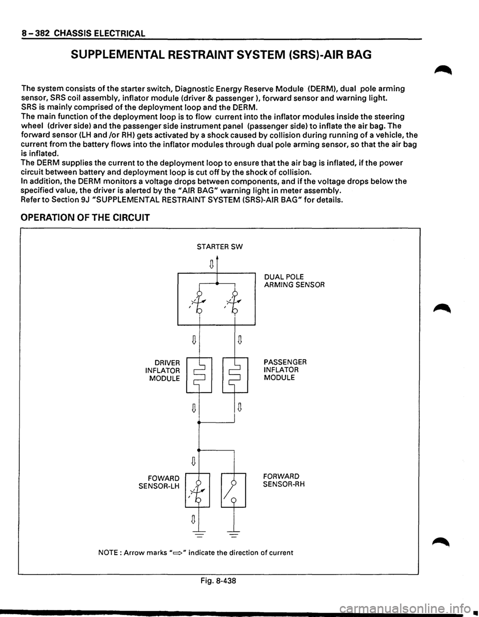
SUPPLEMENTAL RESTRAINT SYSTEM (SRS)-AIR BAG
The system consists of the starter switch, Diagnostic Energy Reserve Module (OERM), dual pole arming
sensor,
SRS coil assembly, inflator module (driver & passenger), forward sensor and warning light.
SRS is mainly comprised of the deployment loop and the DERM.
The main function of the deployment loop is to flow current into the inflator modules inside the steering
wheel (driver side) and the passenger side instrument panel (passenger side) to inflate the air bag. The
forward sensor
(LH and /or RH) gets activated by a shock caused by collision during running of a vehicle, the
current
from the battery flows into the inflator modules through dual pole arming sensor, so that the air bag
is
inflated.
The DERM supplies the current to the deployment loop to ensure that the air bag is inflated, if the power
circuit between battery and deployment loop is cut off by the shock of collision.
In
addition, the DERM monitors a voltage drops between components, and if the voltage drops below the
specified
value, the driver is alerted by the "AIR BAG" warning light in meter assembly.
Refer to Section 9J "SUPPLEMENTAL RESTRAINT SYSTEM (SRS)-AIR BAG" for details.
OPERATION OF THE CIRCUIT
DRIVER
INFLATOR MODULE
FOWARD
SENSOR-LH
D
D
STARTER SW
D
1
DUAL POLE ARMING SENSOR
PASSENGER
INFLATOR
MODULE
FORWARD
SENSOR-RH
NOTE: Arrow marks "c::::>" indicate the direction of current
Fig. 8-438
•
Page 1614 of 1928
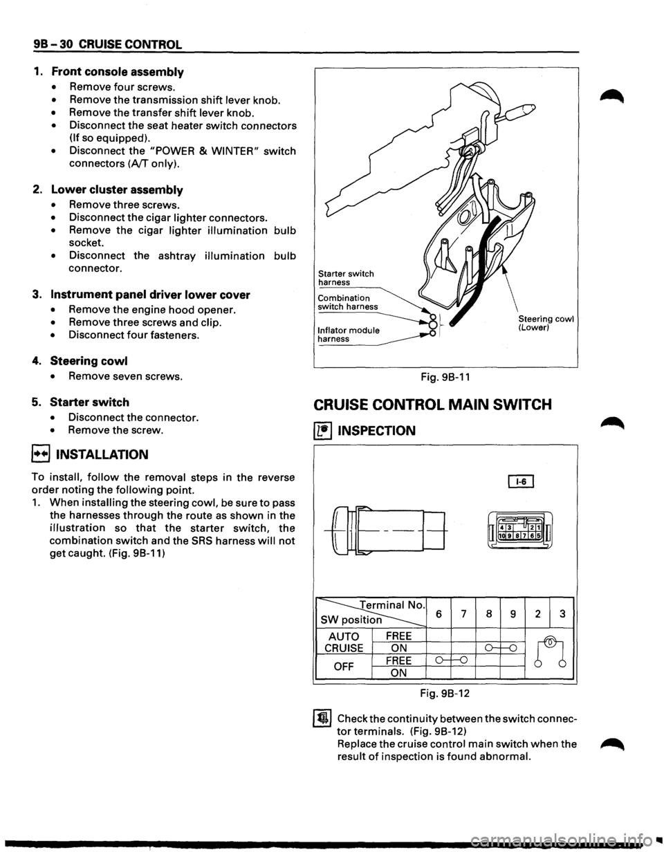
9B-30 CRUISE CONTROL
1. Front console assembly
• Remove four screws.
• Remove the transmission shift lever knob.
• Remove the transfer shift lever knob.
• Disconnect the seat heater switch connectors
(If so equipped).
• Disconnect the "POWER & WINTER" switch
connectors (A/T only).
2. Lower cluster assembly
• Remove three screws.
• Disconnect the cigar lighter connectors.
• Remove the cigar lighter illumination bulb
socket.
• Disconnect the ashtray illumination bulb
connector.
3. Instrument panel driver lower cover
• Remove the engine hood opener.
• Remove three screws and clip.
•
Disconnect four fasteners.
4. Steering cowl
• Remove seven screws.
5. Starter switch
• Disconnect the connector.
• Remove the screw.
8 INSTALLATION
To install, follow the removal steps in the reverse
order noting the following point.
1. When installing the steering cowl, be sure to pass
the harnesses
through the route as shown in the
illustration so that the starter switch, the
combination switch and the SRS harness will not
get caught. (Fig. 98-11)
Starter switch
harness
Combination
switch harness
l._n!~~~o!_ module __..o .~ ~
Fig. 98-11
Steering cowl (Lower)
CRUISE CONTROL MAIN SWITCH
(1!1 INSPECTION
OI1
r-="'
-L
r= t-------uii4J~l "ltl1 u
l
1111ilr9Tsl7lels .,
:::o.,..o-
~ s 6 7 8 9 2 3
AUTO FREE
n
CRUISE ON ()-1---n
OFF FREE o-f--0
ON
Fig. 98-12
ltjl Check the continuity between the switch connec
tor terminals. (Fig. 98-12)
Replace the cruise control main switch when the ~
result of inspection is found abnormal.
Page 1632 of 1928
9J-8 Supplemental Restraint System
DEFINITIONS
AIR BAG -An inflatable cloth cushion designed to
deploy in certain frontal crashes. It supplements the
protection offered by the seat belts by distributing the
impact load more evenly over the vehicle occupant's
head and torso.
ASYNCHRONOUS -Performed in a non-periodic
fashion,i.e.no defined time or interval.
B+-Battery voltage, the voltage available at the battery
at the time of the indicated measurement. With the key
"ON" and the engine not running, the system voltage will
likely be between 12 and 12.5 volts. At idle the voltage
may be 14 to 16 volts. The voltage could be as low as 1
0
volts during engine cranking.
BULB
CHECK-The DERM will cause the "AIR BAG"
warning lamp to flash seven times and then go "OFF"
whenever the ignition switch transitions to the RUN
position from any other ignition switch position and no
malfunctions are detected.
"CONTINUOUS MONITORING"-Tests performed by
the DERM on the
SRS every 1 00 milliseconds while
"Ignition
1" voltage is in the normal operating voltage
range at the DERM.
DATA LINK CONNECTOR(DLC)-Formerly "ALDL'', a
connector which allows communication with an
off-board computer, such as a scan
tool.
DATUM LINE-A base line parallel to the plane of the
underbody or frame from which all vertical
measurements originate.
DEPLOY-To inflate the air bag.
DEPLOYMENT
LOOPS - The circuits which supply
current to the inflator modules to deploy the air bag.
DERM -Diagnostic
energy reserve module which
provides reserve energy to the deployment loops and
performs diagnostic monitoring of
all SRS components.
DIAGNOSTIC TROUBLE CODE(DTC) -Formerly
"Code,"a numerical designator used by the DERM to
indicate specific
SRS malfunctions.
DRIVER CURRENT SOURCE-An output of the DERM
which injects current into the driver inflator module circuit
during the "Initiator Assembly Resistance
Test."
DRIVER INFLATOR
MODULE-An assembly located in
the steering wheel hub consisting of an inflatable air bag,
an inflator and an initiator.
DUAL
POLE ARMING SENSOR-A sensor on the high
side(power side) of the deployment loops that is
calibrated to supply voltage to the inflator modules when
the vehicle velocity changes are severe enough to
warrant arming of the air bags in preparation for
deployment.
EEPROM -Electrically Erasable Programmable Read ~
Only Memory. Memory which retains its contents when
power
is removed from the DERM.
FORWARD LH DISCRIMINATING SENSOR-A sensor
on the low side(ground side) of the deployment loops
which is calibrated to ground the inflator modules when
the vehicle velocity changes are severe enough to
warrant deployment of the air bags.
FORWARD RH DISCRIMINATING SENSOR-A sensor
on the low side(ground side) of the deployment loops
which
is calibrated to ground the inflator modules when
the vehicle velocity changes are severe enough
to
warrant deployment of the air bag.
FORWARD LH SENSOR Eng-Room HARNESS-An
assembly of two correct carrying wires which connects
the Forward
LH discriminating sensor to SRS harness.
FORWARD RH SENSOR Eng-Room HARNESS
JUMPER-An assembly of two current carrying wires
which connects the Forward
RH discriminating sensor to
the
SRS harness.
HIGHER PRIORITY FAULT-Each diagnostic trouble
code
is assigned a priority based on the detectability with
other DTCs present. The priority corresponds to the
detectability of the malfunction ONLY, and does NOT
relate to the criticality of the malfunction with respect to ~
deployment or non-deployment under any given
condition.
IGNITION CYCLE -The voltage at the PERM "Ignition
1"
inputs, with ignition switch "ON," is within the normal
operating voltage range for at least ten seconds before
turning ignition switch
"OFF."
IGNITION1
-A battery voltage(B+)circuit which is only
powered with the ignition switch in the RUN,BULB
TEST,or START positions.
INITIATOR-The electrical component inside the inflator
module which, when sufficient current flows, sets off the
chemical reaction that inflates the air bag.
"INITIATOR ASSEMBLY RESISTANCE TEST"-Tests
performed once each ignition cycle when no
malfunctions are detected during "Turn-ON" or
"Continuous Monitoring." This test checks for the correct
DERM configuration for the vehicle, shorts to
"Ignition 1"
in the deployment loops, high resistance or opens in the
"Driver
Side High," "Driver Side Low," "Passenger Side
High"
and "Passenger Side Low" circuits and measures
the resistance of the inflator assembly consisting of: 1)
Initiators, 2) SRS coil assembly(driver side only), 3)
Connectors and associated wiring.
NORMAL OPERATING VOLTAGE RANGE-The ~
voltage measured between the DERM "Ignition 1" ·
terminals and "Ground" terminals is between 7.25 and 16
volts.
•
Page 1633 of 1928
PASSENGER CURRENT SOURCE -An output of the
DERM which injects current into the passenger inflator
module circuit during the
~Initiator Assembly Resistance
'--"" Test."
PASSENGER INFLATOR MODULE -An assembly
located in the right side of the 1/P consisting of an
inflatable bag, an inflator and an initiator.
SCAN TOOL -An off-board computer used to read
diagnostic information from on-board computers via the
data
link connector.
SERIAL DATA -Information representing the status of
the
SRS.
SRS
-Supplemental Restraint System.
SRS COIL ASSEMBLY-An assembly of two current
carrying coils in the driver deployment loop that allows
the rotation of the steering wheel while maintaining the
continuous contact
of the driver deployment loop to the
driver inflator module.
SRS WIRING HARNESS-The wires and connectors
that electrically connect the components in the
SRS.
1 Supplemental Restraint System 9J-9
"10 MINUTE LOOP TEST' -Portions of the "Initiator
Assembly Resistance Test" are repeated every ten
minutes during an ignition cycle. These are the check for
shorts to
"Ignition 1" in the deployment loops and the
check for an open discriminating sensor interconnect
circuit.
''TURN-ON" -Test which the DERM performs on the
SRS once during each ignition cycle immediately after
"Ignition 1" voltage is applied to the DERM and before
"Continuous Monitoring."
36VLR-The 36-volt loop reserve energy supplies from
the DERM which provide deployment power when
vehicle voltage is
low or lost in a frontal crash.
36 VLR DELAY
-Changing of the 36 VLR power supplies
is
inhibited briefly during "Turn-ON." This allows
detection of certain malfunctions related to "Ignition 1"
voltage which cannot be tested with 36 volts present.
Page 1637 of 1928
Supplemental Restraint System 9J-13
ON-VEHICLE SERVICE
SERVICE PRECAUTIONS
WARNING: WHEN PERFORMING SERVICE ON OR
AROUND SRS COMPONENTS OR SRS WIRING,
FOLLOW
THE PROCEDURES LISTED BELOW TO
TEMPORARILY DISABLE THE SRS. FAILURE TO
FOLLOW PROCEDURES COULD RESULT IN
POSSIBLE AIR
BAG DEPLOYMENT, PERSONAL
INJURY OR OTHERWISE
UNNEEDED SRS
REPAIRS.
The DERM in Driver-Passenger SRS can maintain
sufficient voltage to cause a deployment for up to 2
minutes after the ignition switch is turned
"OFF," the
battery is disconnected, or the fuse powering the DERM
is removed.
Many of the service procedures require removal of the
"AIR BAG" fuse, and disconnection of the inflator
modules from the deployment loop to avoid an accidental
deployment.
If the inflator module is disconnected from
the deployment loop as noted in the "Disabling the
SRS"
procedure that follows, service can begin immediately
without waiting for the 2-minute time period to expire.
DISABLING THE SRS
REMOVAL
Turn the ignition switch to "OFF"
1. Remove SRS fuse C-21, C-22, C-23 and C-24 from
left dash side lower fuse block.
2. Disconnect yellow 3-way connector at the base of
steering column.
3. Remove 1/P compartment door assembly, Refer to
"Passenger inflator module replacement" in section
9J-132.
4. Disconnect yellow 4-way connector behind the 1/P
compartment door assembly.
IMPORTANT
• With the "AIR BAG" fuse removed and ignition switch
"ON," if Fuse 21 left. the "AIR BAG" warning lamp will
be "ON." This is normal operation and does not
indicate an
SRS malfunction.
ENABLING THE SRS
INSTALLATION
Turn ignition switch to "LOCK" and remove key.
1. Connect yellow 4-way connector for passenger
inflator module.
2. 1/P compartment door assembly, Refer to
"Passenger inflator module replacemenf' in section
9J-3.
3. Connect yellow 2-way connector at the base of the
steering column.
4. Install "AIR BAG" fuse C-21, C-22, C-23 and C-24 to
left dash side lower fuse block.
Turn ignition switch to
"RUN" and verify that the "AIR
BAG"
warning lamp flashes seven times and then turns
"OFP' If it does not operate as described, perform the
"SRS Diagnostic System Check" in section 9J-2.
HANDLING/INSTALLATION/DIAGNOSIS
1. Inflator modules should not be subjected to
temperatures above
65°C{150°F).
2. Discriminating sensors, inflator modules, arming
sensors, or DERMs should not be used if they have
been dropped from a height
of 91.4 centimeters
{3feet).
3. When a discriminating sensor or arming sensor is
replaced, it must be oriented with the arrow on the
sensor pointing toward the front of the vehicle.
It is
very important for the discriminating sensors and
arming sensor to be located flat on the mounting
surface, parallel to the vehicle datum line.
It is
important that the sensor mounting surface is free of
any dirt or other foreign material.
4. Do not apply power to the SRS unless all
components are connected or a diagnostic chart
requests it, as this
will set a diagnostic trouble code.
5. The "SRS Diagnostic System Check" must be the
starting point of any
SRS diagnostics. The "SRS
Diagnostic System Check" will verify proper "AIR
BAG"
warning lamp operation and will lead you to the
correct chart to diagnose any
SRS malfunctions.
Bypassing these procedures may result
in extended
diagnostic time, incorrect diagnosis, and incorrect
parts replacements.
Page 1646 of 1928
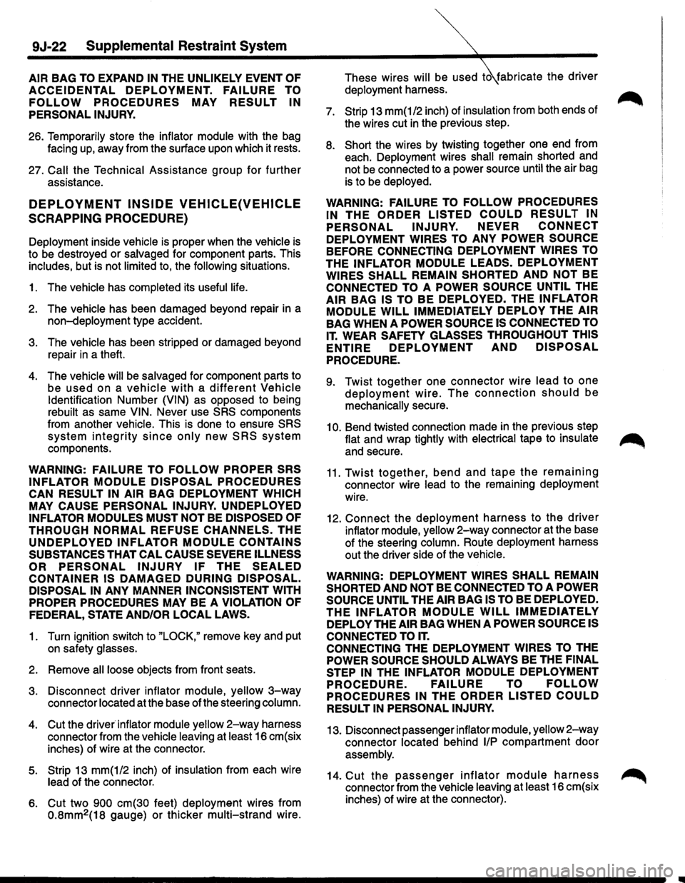
9J-22 Supplemental Restraint System
AIR BAG TO EXPAND IN THE UNLIKELY EVENT OF
ACCEIDENTAL DEPLOYMENT. FAILURE TO
FOLLOW PROCEDURES MAY RESULT IN
PERSONAL INJURY.
26. Temporarily store the inflator module with the bag
facing up, away from the surface upon which it rests.
27.
Call the Technical Assistance group for further
assistance.
DEPLOYMENT INSIDE VEHICLE(VEHICLE
SCRAPPING PROCEDURE)
Deployment inside vehicle is proper when the vehicle is
to be destroyed or
salvaged for component parts. This
includes, but is not limited to, the following situations.
1. The vehicle has completed its useful life.
2. The vehicle has been damaged beyond repair in a
non-deployment type accident.
3. The vehicle has been stripped or damaged beyond
repair
in a theft.
4. The vehicle will be salvaged for component parts to
be
used on a vehicle with a different Vehicle
Identification Number (VIN) as opposed to being
rebuilt as same VIN. Never use SRS components
from another
vehicle. This is done to ensure SRS
system integrity since only new SRS system
components.
WARNING: FAILURE TO FOLLOW PROPER SRS
INFLATOR MODULE DISPOSAL PROCEDURES
CAN RESULT IN AIR BAG DEPLOYMENT WHICH
MAY CAUSE PERSONAL INJURY. UNDEPLOYED
INFLATOR MODULES MUST NOT BE DISPOSED OF
THROUGH NORMAL REFUSE CHANNELS. THE
UNDEPLOYED INFLATOR MODULE CONTAINS
SUBSTANCES THAT CAL CAUSE SEVERE ILLNESS
OR
PERSONAL INJURY IF THE SEALED
CONTAINER IS DAMAGED DURING DISPOSAL.
DISPOSAL IN ANY MANNER INCONSISTENT WITH
PROPER PROCEDURES MAY BE A VIOLATION OF
FEDERAL, STATE AND/OR LOCAL LAWS.
1. Turn ignition switch to "LOCK," remove key and put
on safety glasses.
2. Remove all loose objects from front seats.
3. Disconnect driver inflator module, yellow 3-way
connector located at the base of the steering column.
4. Cut the driver inflator module yellow 2-way harness
connector from the
vehicle leaving at least 16 cm(six
inches) of wire at the connector.
5. Strip 13 mm(1/2 inch) of insulation from each wire
lead of the connector.
6. Cut two 900 cm(30 feet) deployment wires from
0.8mm2(18 gauge) or thicker
multi-strand wire. These
wires
will be used to fabricate the driver
deployment harness.
7. Strip 13 mm(1/2 inch) of insulation from both ends of
the wires cut
in the previous step.
8. Short the wires by twisting together one end from
each. Deployment wires
shall remain shorted and
not
be connected to a power source until the air bag
is to be
deployed.
WARNING: FAILURE TO
FOLLOW PROCEDURES
IN
THE ORDER LISTED COULD RESULT IN
PERSONAL INJURY. NEVER CONNECT
DEPLOYMENT WIRES TO ANY POWER SOURCE
BEFORE CONNECTING DEPLOYMENT WIRES TO
THE INFLATOR MODULE LEADS. DEPLOYMENT
WIRES SHALL REMAIN SHORTED AND NOT BE
CONNECTED TO A POWER SOURCE UNTIL THE
AIR BAG IS TO BE DEPLOYED. THE INFLATOR
MODULE WILL IMMEDIATELY DEPLOY THE AIR
BAG WHEN A POWER SOURCE IS CONNECTED TO
IT. WEAR SAFETY GLASSES THROUGHOUT THIS
ENTIRE DEPLOYMENT AND DISPOSAL
PROCEDURE.
9. Twist together one connector wire lead to one
deployment wire. The connection should be
mechanically secure.
10. Bend twisted connection made in the previous step
flat and wrap tightly with electrical tape to insulate ~
and secure.
11. Twist together, bend and tape the remaining
connector wire lead to the remaining deployment
wire.
12. Connect the deployment harness to the driver
inflator module, yellow 2-way connector at the base
of the steering
column. Route deployment harness
out the driver side of the
vehicle.
WARNING:
DEPLOYMENT WIRES SHALL REMAIN
SHORTED
AND NOT BE CONNECTED TO A POWER
SOURCE UNTIL THE AIR BAG IS TO BE DEPLOYED.
THE INFLATOR MODULE WILL IMMEDIATELY
DEPLOY THE AIR BAG WHEN A POWER SOURCE IS
CONNECTED TO IT.
CONNECTING THE DEPLOYMENT WIRES TO THE
POWER
SOURCE SHOULD ALWAYS BE THE FINAL
STEP IN
THE INFLATOR MODULE DEPLOYMENT
PROCEDURE. FAILURE TO FOLLOW
PROCEDURES IN THE ORDER LISTED COULD
RESULT IN PERSONAL INJURY.
13. Disconnect passenger inflator module, yellow 2-way
connector located behind 1/P compartment door
assembly.
14. Cut the passenger inflator module harness
connector from the vehicle leaving at least 16 cm(six
inches) of wire at the connector).
Page 1665 of 1928
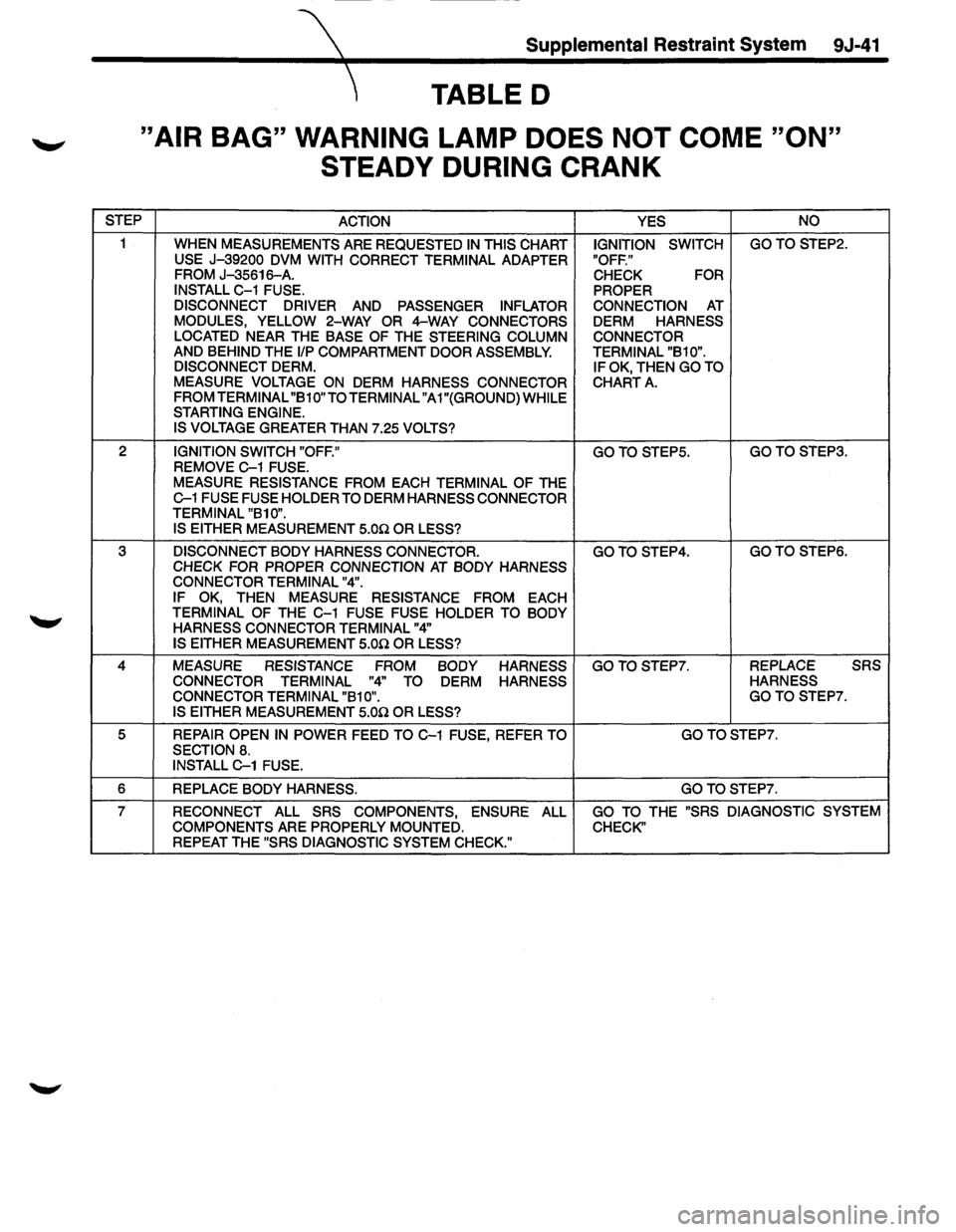
Supplemental Restraint System 9J-41
TABLED
"AIR BAG" WARNING LAMP DOES NOT COME "ON"
STEADY DURING
CRANK
STEP
ACTION YES NO
1
WHEN MEASUREMENTS ARE REQUESTED IN THIS CHART IGNITION SWITCH GOTO STEP2.
USE
J-39200 DVM WITH CORRECT TERMINAL ADAPTER "OFF."
FROM J-35616-A. CHECK FOR
INSTALL C-1 FUSE.
PROPER
DISCONNECT DRIVER
AND PASSENGER INFLATOR CONNECTION AT
MODULES, YELLOW 2-WAY OR 4-WAY CONNECTORS DERM HARNESS
LOCATED NEAR THE BASE OF THE STEERING COLUMN CONNECTOR AND BEHIND THE liP COMPARTMENT DOOR ASSEMBLY. TERMINAL "B10".
DISCONNECT DERM. IF OK, THEN GO TO MEASURE VOLTAGE ON DERM HARNESS CONNECTOR CHARTA. FROM TERMINAL "B1 0" TO TERMINAL "A 1"(GROUND) WHILE
STARTING ENGINE.
IS VOLTAGE
GREATER THAN 7.25 VOLTS?
2 IGNITION SWITCH "OFF." GOTOSTEP5. GOTOSTEP3.
REMOVE G-1 FUSE.
MEASURE RESISTANCE FROM
EACH TERMINAL OF THE G-1 FUSE FUSE HOLDER TO DERM HARNESS CONNECTOR
TERMINAL "B10".
IS EITHER
MEASUREMENT 5.00 OR LESS?
3 DISCONNECT BODY HARNESS CONNECTOR. GOTOSTEP4. GOTOSTEP6.
CHECK FOR PROPER CONNECTION AT BODY HARNESS
CONNECTOR TERMINAL "4".
IF OK,
THEN MEASURE
RESISTANCE FROM EACH TERMINAL OF THE C-1 FUSE FUSE HOLDER TO BODY
HARNESS CONNECTOR TERMINAL "4"
IS EITHER
MEASUREMENT 5.00 OR LESS?
4 MEASURE
RESISTANCE FROM BODY HARNESS GOTOSTEP7. REPLACE SRS
CONNECTOR TERMINAL
"4" TO DERM HARNESS HARNESS
CONNECTOR TERMINAL "B10". GOTOSTEP7.
IS EITHER MEASUREMENT 5.00 OR LESS?
5 REPAIR OPEN IN POWER FEED TO C-1 FUSE, REFER TO GO
TO STEP?.
SECTION 8. INSTALL G-1 FUSE.
6 REPLACE BODY HARNESS. GOTOSTEP7.
7 RECONNECT ALL SRS COMPONENTS, ENSURE ALL GO TO THE "SRS DIAGNOSTIC SYSTEM
COMPONENTS
ARE PROPERLY MOUNTED. CHECK" REPEAT THE "SRS DIAGNOSTIC SYSTEM CHECK."