clutch ISUZU TROOPER 1995 Manual Online
[x] Cancel search | Manufacturer: ISUZU, Model Year: 1995, Model line: TROOPER, Model: ISUZU TROOPER 1995Pages: 1928
Page 1023 of 1928
A4
D16
D9
C1
D1
D12
A7
AB
TRANSMISSION
A3 C10 C12
B9
A2
All A9 A10
BB C15
B6 C16
CONTROL
B3
B10 C14
C7
B4
D14
MODULE
D7 D6
D5
C5 D4 C6
B5
B12
(TCMI
A12 B11
DB
CB
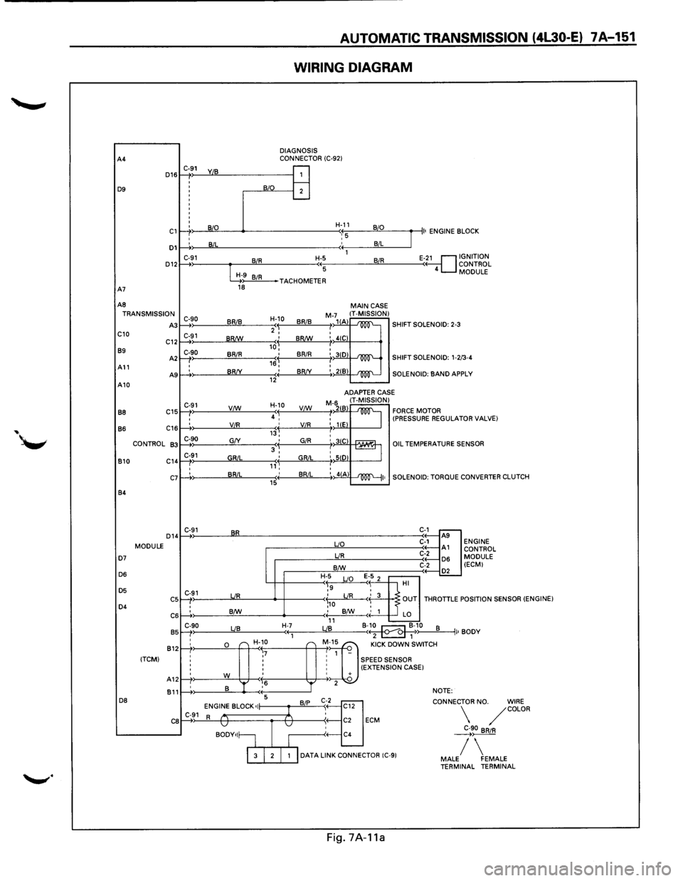
AUTOMATIC TRANSMISSION (4l30-E) 7 A-151
WIRING DIAGRAM
DIAGNOSIS
CONNECTOR (C-921 C-91
1: : j
B/0 B
I
I B/L
C-91 BIR :
G9 BIR 18
C-90 BRIB )
C-91 ) BR!W
C-90
BRIR I
I BR/Y )
C-91 V/W
'
' VIR )
C-90 G/Y
C-91 GRIL ) '
' BRIL :
C-91 BR
C-91 UR
: B/W
C-90 LIB )
;&"
r-r ,7 ' '
' '
' '
rt' w ,6
' B '
1---+: 5
ENGINE BLOCK •I C-91 R v
BODY•I~
H-11 B/0
'::5 B/L
1
H-5 BIR
(( 5
J
II• ENGINE B LOCK
E-~1 GNITION
ONTROL
MODULE ( 4 c
TACHOMETER
H-10
BRIB 'I 2 I
,J BR!W
I BRIR 16, ' BR/Y (( 12
H-10
4 ~ VC:!:f._
,j VIR
' GIR 3, ' GRIL ,,'~ ' BRIL (( 15
H-7 ((1
---
'r
B/P
1
v
I
MAIN CASE M-71(1 IT-MISSION) /1 A -'m'-SHIFT SOLENOID: 2-3 I I 4(C
: 3(0 -'m'-SHIFT SOLENOID: 1-2 /3-4
:, 21B -'100"'--SOLENOID: BAND AP PLY
ADAPTER
CASE
M-6211 IT-MISSION) FORCE MOTOR I 2 B
~ : liE (PRESSURE REGULAT OR VALVE)
I : 31C rAAUr1 '-== : SID I :, 41A ~I•
uo
UR
B/W
H-5
E 1-5 2 ~9 LIO
'
OIL TEMPERATURES
SOLENOID:
TORQUE
C-1 ..---A9 C-1 A1 C-2 D6 C-2
.-----.£L HI .?
ENSOR
CONVERTER CLUTCH
ENGINE CONTROL
MODULE (ECMI
\,o LIR < 3 OUT THROTTLE P OSITION SENSOR (ENGINE) ; B/W
' 1 LO 11 B-~10 LIB B ( 2 1 ~) II• BODY
"] "" oow' ""''" 1 -
: SPEED SENSOR : (EXTENSION CASE I ' + 2 NOTE:
't]
CONNEC
C12
: C2 ECM
C4 TOR
NO. WIRE /COLOR
~90 BRIR
I 3 I 2 I 1 I DATA LINK CONNECTOR (C-91 / MALE FEMALE TERMINAL TERMINAL
Fig.
7A-11a
Page 1038 of 1928
7A-166 AUTOMATIC TRANSMISSION (4l30-E)
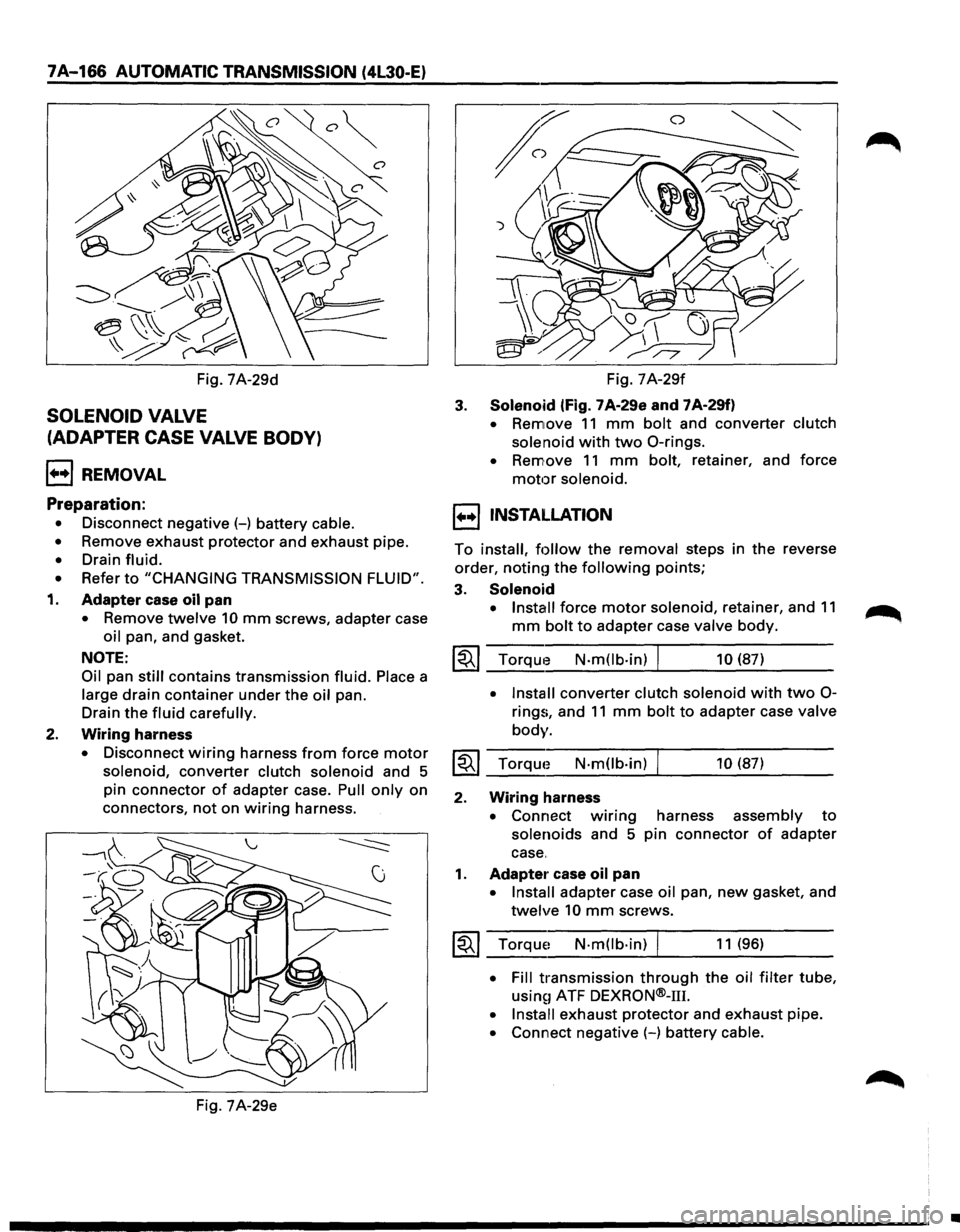
Fig. 7A-29d
SOLENOID VALVE
(ADAPTER CASE VALVE BODY)
l++l REMOVAL
Preparation:
• Disconnect negative(-) battery cable.
• Remove exhaust protector and exhaust pipe.
• Drain fluid.
• Refer to "CHANGING TRANSMISSION FLUID".
1. Adapter case oil pan
• Remove twelve 10 mm screws, adapter case
oil pan, and gasket.
NOTE:
Oil pan still contains transmission fluid. Place a
large
drain container under the oil pan.
Drain
the fluid carefully.
2. Wiring harness
• Disconnect wiring harness from force motor
solenoid, converter clutch solenoid and 5
pin
connector of adapter case. Pull only on
connectors,
not on wiring harness.
Fig. 7A-29e Fig.
7A-29f
3. Solenoid (fig. 7 A-29e and 7 A-29f)
• Remove 11 mm bolt and converter clutch
solenoid
with two 0-rings.
• Remove 11 mm bolt, retainer, and force
motor solenoid.
1••1 INSTALLATION
To install, follow the removal steps in the reverse
order,
noting the following points;
3. Solenoid
• Install force motor solenoid, retainer, and 11
mm bolt to adapter case valve body.
~~~ Torque N-m(lb-in) I 10 (87)
• Install converter clutch solenoid with two 0-
rings, and 11 mm bolt to adapter case valve
body.
~~~ Torque N-mOb·in) 10 (87)
2. Wiring harness
• Connect w1nng harness assembly to
solenoids and 5 pin connector of adapter
case.
1. Adapter case oil pan
• Install adapter case oil pan, new gasket, and
twelve 10 mm screws.
~~~ Torque~ N·mOb·in) I 11 (96)
• Fill transmission through the oil filter tube,
usin~1 ATF DEXRON®-111.
• Install exhaust protector and exhaust pipe.
• Connect negative (-) battery cable.
•
Page 1040 of 1928
7A-168 AUTOMATIC TRANSMISSION (4L30-E)
3. Manual detent
• Install roller and spring assembly.
• Install
two 13 mm screws.
~~~ Torque N·m(lb.ft) I 20 (15)
2. Oil filter
• Install oil filter and three 13 mm screws.
~~~ Torque N-m(lb.ft) I 20 (15)
1. Main case oil pan
• Install oil pan gasket, magnet, oil pan and
sixteen
10 mm screws.
~~~ Torque N·m(lb-in) I 11 (96)
• Fill transmission through the oil filler tube,
using ATF
DEXRON®-111.
• Install exhaust pipe and exhaust protector.
• Connect negative (-) battery cable.
VALVE BODY ASSEMBLY (ADAPTER CASE)
1++1 REMOVAL
Preparation:
• Disconnect negative (-) battery cable.
•
Remove exhaust protector and exhaust pipe.
• Drain fluid.
•
Refer to "CHANGING TRANSMISSION FLUID".
1. Adapter case oil pan
• Remove twelve 10 mm screws, adapter case
oil pan and gasket.
NOTE:
Oil pan still contains transmission fluid. Place a
large drain container under the oil pan.
Drain the
fluid carefully.
2. Wiring harness
• Disc;:mnect wiring harness from force motor
solenoid, converter clutch solenoid and 5
pin
connector of adapter case. Pull only on
connectors,
not on wiring harness.
• Remove wiring harness.
3. Adapter case valve body
• Seve~n 13 mm screws, adapter case valve
body assembly, transfer plate and two
gaskets.
1++1 INSTALLATION
To install, follow the removal steps in the reverse
order,
notin~r the following points;
3. Adapter case valve body
• Inspect electrical 5 pin connector and seal of
adapter case. Replace if necessary.
• Install wiring harness assembly in bottom
of adapter case.
• Install gasket, transfer plate and gasket.
• Install adapter case valve body complete
and seven 13 mm screws.
~~~ Torque1 N·mOb·ft) 20 (15)
2. Wiring harness
• Connect harness assembly to converter
clutch solenoid and force motor.
1. Adapter case oil pan
• Instal!! oil pan gasket, oil pan and twelve 10
mm screws.
~~~ Torque N-m(lb-in) I 11 (96)
• Fill transmission through the oil filter tube,
using1 ATF DEXRON®-m.
• Install exhaust pipe and exhaust protector. ~
• Connect negative (-) battery cable.
•
Page 1042 of 1928
7 A-170 AUTOMATIC TRANSMISSION (4L30-E)
TRANSMISSION OIL TEMPERATURE
SENSOR (ADAPTER CASE)
1•+1 REMOVAL
Preparation:
• Disconnect negative (-) battery cable.
•
Remove exhaust protector and exhaust pipe.
• Drain fluid.
•
Refer to "CHANGING TRANSMISSION FLUID".
1. Adapter case oil pan
• Remove twelve 10 mm screws, adapter case
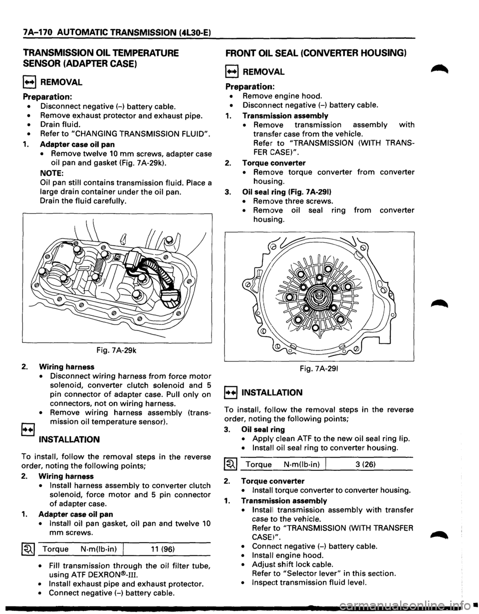
oil pan and gasket (Fig. 7 A-29k).
NOTE:
Oil
pan still contains transmission fluid. Place a
large drain container under the oil pan.
Drain the
fluid carefully.
Fig. 7A-29k
2. Wiring harness
• Disconnect wiring harness from force motor
solenoid, converter clutch solenoid and 5
pin connector
of adapter case. Pull only on
connectors,
not on wiring harness.
• Remove wiring harness assembly (trans
B mission oil temperature sensor).
INSTALLATION
To install, follow the removal steps in the reverse
order, noting the
following points;
2.
Wiring harness
• Install harness assembly to converter clutch
solenoid,
force motor and 5 pin connector
of adapter case.
1. Adapter case oil pan
• Install oil pan gasket, oil pan and twelve 10
mm screws.
~~~ Torque N·mOb·in) I 11 (96)
• Fill transmission through the oil filter tube,
using ATF
DEXRON®-111.
• Install exhaust pipe and exhaust protector.
• Connect negative (-) battery cable.
FRONT OIL SEAL (CONVERTER HOUSING)
l++l REMOVAL
Preparation:
• Removt~ engine hood.
• Disconnect negative (-) battery cable.
1. Transmission assembly
•
Remove transmission assembly with
transfer case from the vehicle.
Refer to "TRANSMISSION (WITH TRANS
FER CASE)".
2. Torque converter
• Remove torque converter from converter
housing.
3.
Oil seal ring (Fig. 7 A-291)
• Remove three screws.
• Remove oil seal ring from converter
housing.
Fig.
7A-291
I++IINSTALLATION
To install, follow the removal steps in the reverse
order, noting the
following points;
3. Oil seal ring
• Apply clean ATF to the new oil seal ring lip.
• Install oil seal
ring to converter housing.
~~~ Torque N·mOb·in) I 3 (26)
2. Torque converter
• Install torque converter to converter housing.
1. Transmission assembly
• Install
transmission assembly with transfer
case
to the vehicle.
Refer to "TRANSMISSION (WITH TRANSFER
CASE I".
• Connoct negative (-) battery cable.
• Install
engine hood.
• Adjust shift lock cable.
Refer to "Selector lever" in this section.
• Inspect transmission fluid level.
•
Page 1046 of 1928
7A-174 AUTOMATIC TRANSMISSION (4L30·E)
1•!•1 biSASSEMBLV
During the disassembly and reassembly of the
following components, perform the following:
• Wash each part thoroughly and blow air
through each oil passage and groove to
eliminate blockage.
• Seal rings, roll pins and gaskets should be
replaced
with new parts.
• When assembling the components, apply
DEXRON®-m Automatic Transmission Fluid
(ATF)
to each seal, rotating part and sliding
part.
• Do not dip those parts having a facing, such as
drive plate for clutch or brake, in the cleaner
when washing it with solvent.
Also, always wash
it with new ATF two or
three times after cleaning with solvent.
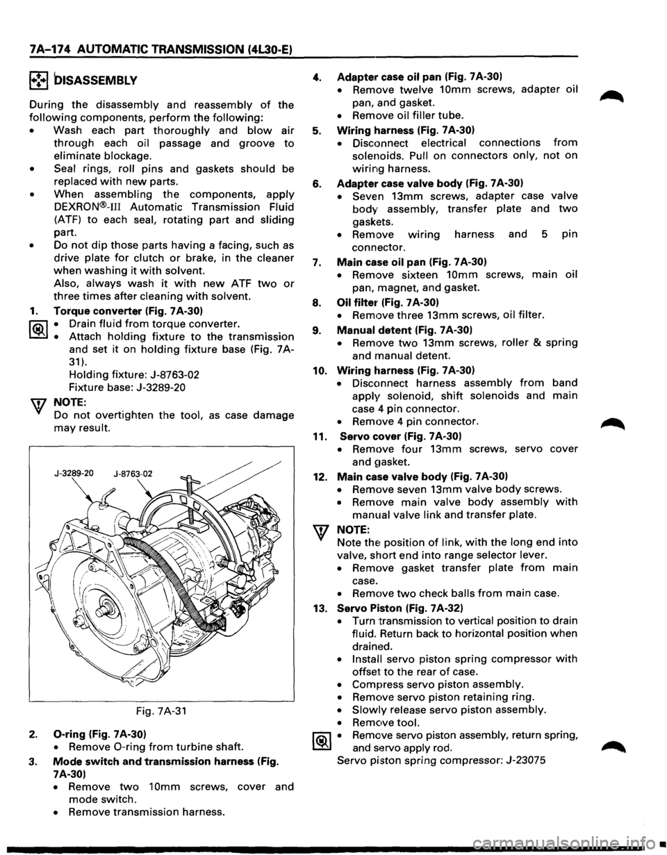
1. Torque converter (Fig. 7A-30)
l"i:\1 • Drain fluid from torque converter.
~ • Attach holding fixture to the transmission
and set it on holding fixture base (Fig. 7A-
31).
Holding fixture: J-8763-02
Fixture base: J-3289-20
w NOTE:
Do
not overtighten the tool, as case damage
may result.
Fig. 7A-31
2. 0-ring (Fig. 7 A-30)
•
Remove 0-ring from turbine shaft.
3. Mode switch and transmission harness (Fig.
7A-30)
•
Remove two 10mm screws, cover and
mode switch.
• Remove transmission harness.
4.
5.
6.
7.
8.
9.
10.
11.
12.
Adapter case oil pan (Fig. 7 A-30)
•
Remove twelve 10mm screws, adapter oil
pan, and gasket.
• Remove oil filler tube.
Wiring harness (Fig. 7 A-30)
•
Disconnect electrical connections from
solenoids. Pull on connectors only, not on
wiring harness.
Adapter case valve body (Fig. 7A-30)
• Seven
13mm screws, adapter case valve
body assembly, transfer plate and two
gaskets.
• Remove wmng harness and 5 pin
connector.
Main case oil pan (Fig. 7 A-30)
•
Remove sixteen 10mm screws, main oil
pan, magnet, and gasket.
Oil filter· (Fig. 7 A-30)
•
Remove three 13mm screws, oil filter.
Manual detent (Fig. 7 A-30)
•
Remove two 13mm screws, roller & spring
and manual detent.
Wiring harness (Fig. 7 A-30)
•
Disconnect harness assembly from band
apply solenoid, shift solenoids and main
case 4 pin connector.
• Remove 4 pin connector.
Servo cover (Fig. 7 A-30)
•
Remove four 13mm screws, servo cover
and
~1asket.
Main case valve body (Fig. 7 A-30)
•
Remove seven 13mm valve body screws.
• Remove main valve body assembly with
manual valve link and transfer plate.
NOTE: Note
thE! position of link, with the long end into
valve, short end into range selector lever.
• Remove gasket transfer plate from main
case.
• Remove two check balls from main case.
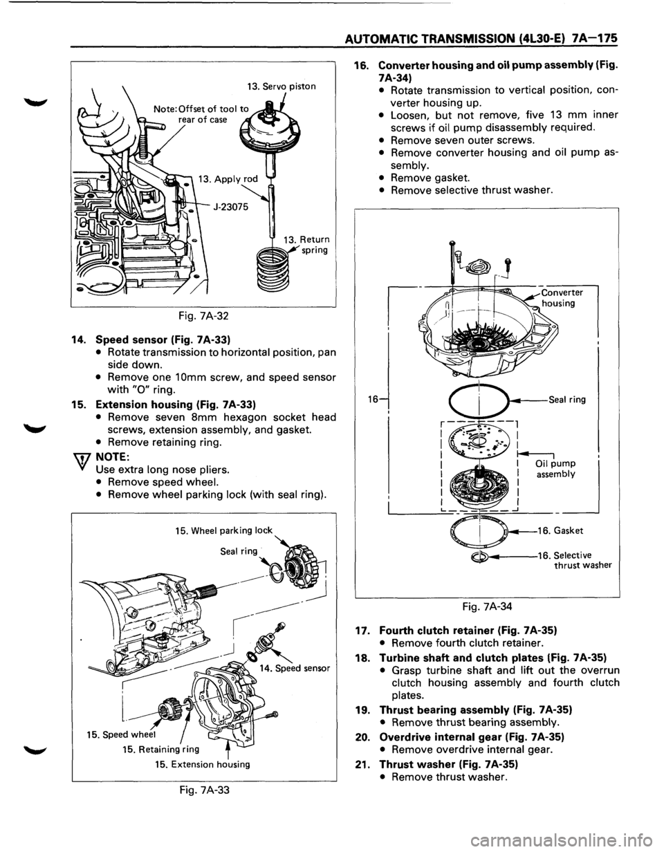
13.
Servo Piston (Fig. 7A-32)
• Turn transmission to vertical position to drain
fluid. Return back
to horizontal position when
drained.
• Install servo piston spring compressor with
offset to the rear of case.
• Compress servo piston assembly.
• Remove servo piston retaining ring.
• Slowly release servo piston assembly.
• Remove tool.
1®.1 • Remove servo piston assembly, return spring,
and servo apply rod.
Servo piston spring compressor: J-23075
•
Page 1047 of 1928
13. Servo piston
Fig. 7A-32
14. Speed sensor (Fig. 7A-33)
• Rotate transmission to horizontal position, pan
side down.
• Remove one 1 Omm screw, and speed sensor
with "0" ring.
15. Extension housing (Fig. 7 A-33)
• Remove seven 8mm hexagon socket head
screws, extension assembly, and gasket.
• Remove retaining ring.
\fl NOTE:
V Use extra long nose pliers.
• Remove speed wheel.
• Remove wheel parking lock (with seal ring).
15. Wheel parking lock
Seal:~
15. Retaining ring
15. Extension housing
Fig. 7A-33
AUTOMATIC TRANSMISSION (4L30-E) 7A-175
16. Converter housing and oil pump assembly (Fig.
7A-34)
16
• Rotate transmission to vertical position, con
verter housing up.
• Loosen, but not remove, five 13 mm inner
screws
if oil pump disassembly required.
• Remove seven outer screws.
• Remove converter housing and oil pump as
sembly.
• Remove gasket.
• Remove selective thrust washer.
~---16. Selective thrust washer
Fig. 7A-34
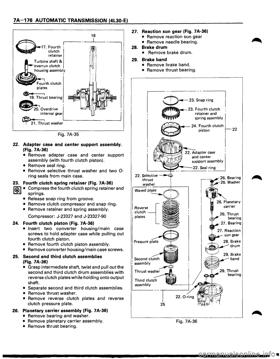
17. Fourth clutch retainer (Fig. 7A-35)
• Remove fourth clutch retainer.
18. Turbine shaft and clutch plates (Fig. 7A-35)
• Grasp turbine shaft and lift out the overrun
clutch housing assembly and fourth
clutch
plates.
19. Thrust bearing assembly (Fig. 7A-35)
• Remove thrust bearing assembly.
20. Overdrive internal gear (Fig. 7A-35)
• Remove overdrive internal gear.
21. Thrust washer (Fig. 7A-35)
• Remove thrust washer.
Page 1048 of 1928
7A-176 AUTOMATIC TRANSMISSION (4l30-E)
~-17. Fourth •
~ clutch retainer
Turbine shaft
& overrun clutch
housing assembly I
Fig. 7A-35
18
22. Adapter case and center support assembly.
(Fig. 7 A-36)
• Remove adapter case and center support
assembly (with fourth clutch piston).
• Remove seal ring.
• Remove selective thrust washer and two 0-
ring seals from main case.
23. Fourth clutch spring retainer (Fig. 7A-36)
~ • Cor:npress the fourth clutch spring retainer and
spnngs.
• Release snap ring from groove.
• Remove clutch compressor and snap ring.
• Remove retainer and spring assembly.
Compressor: J-23327 and J-23327-90
24. Fourth clutch piston (Fig. 7A-36)
• Insert two converter housing/main case
screws to
hold adapter case while pulling out
fourth clutch piston.
• Remove fourth clutch piston assembly.
•
Remove converter housing/main case screws.
25. Second and third clutch assemblies
(Fig. 7A-36)
• Grasp intermediate shaft, twist and pull out the
second and third
clutch drum assemblies with
reverse
clutch plates while holding onto output
shaft.
• Separate second and third clutch assemblies.
•
Remove thrust washer.
• Remove reverse clutch plates and reverse
clutch pressure plate.
26. Planetary carrier assembly (Fig. 7A-36)
• Remove bearing and washer.
• Remove planetary carrier assembly.
•
Remove thrust bearing.
27. Reaction sun gear (Fig. 7A-36)
• Remove reaction sun gear
• Remove needle bearing.
28. Brake drum
• Remove brake drum.
29. Brake band
• Remove brake band.
• Remove thrust bearing.
,-ii--23.~:.~
I 23. Fou_rth clutch :
1 reta~ner and
' spring
assembly
Reverse'-[. 1 clutch
' plates
~~~~ ..... -24. Fourth clutch piston 22
. 27. Re:~~~rn
Second
clutch : assembly
~
Thrustwa~~
Third clutch ._
assembly -
25
Fig. 7A-36
Brake drum
. 29. Brake
band
•
Page 1050 of 1928
7A-178 AUTOMATIC TRANSMISSION (4L30-E)
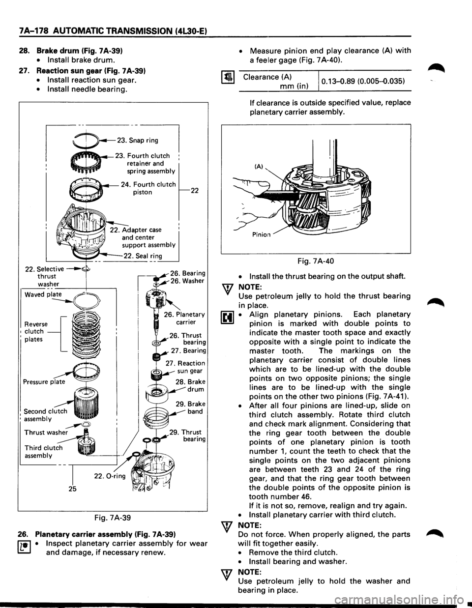
28. Brake drum (fig. 7 A-39)
27.
• Install brake drum.
Reaction sun gear (Fig. 7A-39)
• Install reaction sun gear.
• Install needle bearing.
23.S~a=l
4'i'fl._.l4--23. Fourth clutch :
retainer and
spring
assembly
~~..,...~---24. Fourth clutch
Waved
Reverse{ 1 clutch I plates
1 Second clutch ' assembly
~ Thrust wash~
Third clut~ q_ assembly .
25
Fig. 7A-39
piston
26. Planetary carrier assembly (Fig. 7 A-39)
22
IL•I • Inspect planetary carrier assembly for wear
and damage, if necessary renew.
• Measure pinion end play clearance (A) with
a feeler gage (Fig. 7A-40).
Clearance (A)
mm (in) 0.13-0.89 (0.005-0.035)
If clearance
is outside specified value, replace
planetary
carrier assembly.
Fig. 7A-40
• Install the thrust bearing on the output shaft.
\f NOTE:
Use petmleum jelly to hold the thrust bearing
in
place.
~·
•
Align planetary pinions. Each planetary
pinion is marked with double points to
indicate the master tooth space and exactly
opposite with a single point to indicate the
master tooth. The markings on the
planetary carrier consist of double lines
which are to be lined-up with the double
points on two opposite pinions; the single
lines
are to be lined-up with the single
points on the other two pinions (Fig. 7 A-41 ).
After all four pinions are lined-up, slide on
third clutch assembly. Rotate third clutch
and check mark alignment. Considering that
the ring gear tooth between the double
points of one planetary pinion is tooth
number 1, count the teeth to check that the
singh~ points on the two adjacent pinions
are between teeth 23 and 24 of the ring
gear, and
that the ring gear tooth between
the
double points of the opposite pinion is
tooth number 46.
If it is not so, remove, realign and try again.
• Install planetary carrier with third clutch.
\f NOTE:
Do not force. When properly aligned, the parts
will fit together easily.
•
Remove the third clutch.
• Install
bearing and washer.
\f NOTE:
Use petroleum jelly to hold the washer and
bearing in
place.
•
Page 1051 of 1928
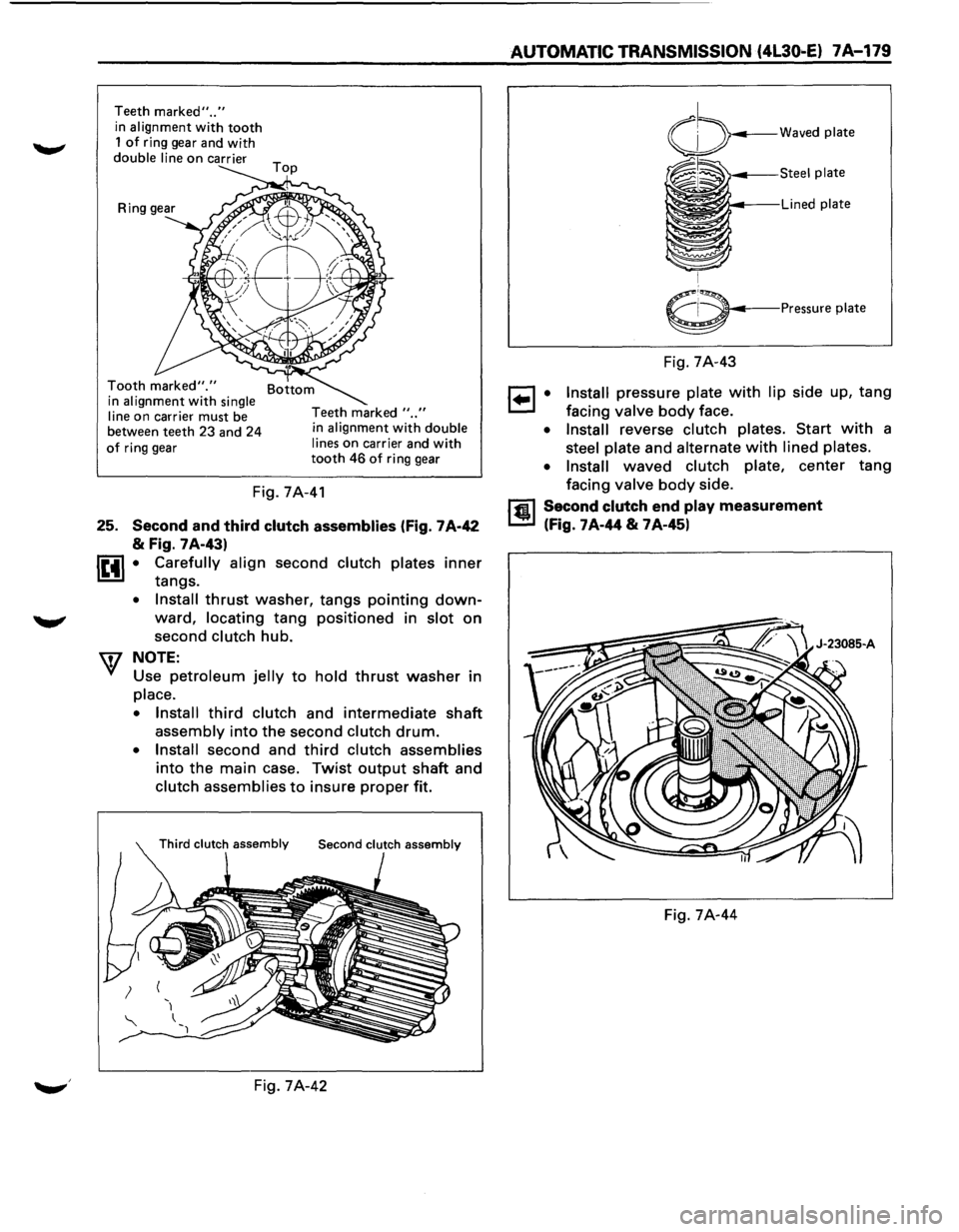
Teeth marked" .. "
in alignment with tooth 1 of ring gear and with
double line on carrier
Tooth marked"." in alignment with single
line
on carrier must be
between teeth 23 and 24
of ring gear Teeth
marked
" .. " in alignment with double
lines
on carrier and with tooth 46 of ring gear
Fig. 7A-41
25. Second and third clutch assemblies (Fig. 7 A-42
& Fig. 7A-43)
lttl • Carefully align second clutch plates inner
tangs.
• Install thrust washer, tangs pointing down
ward, locating tang positioned in slot on
second clutch hub.
W NOTE:
Use petroleum jelly to hold thrust washer in
place.
• Install
third clutch and intermediate shaft
assembly into the second clutch drum.
• Install second and third clutch assemblies
into the main case. Twist output shaft and
clutch assemblies to insure proper fit.
Fig. 7A-42
AUTOMATIC TRANSMISSION (4L30·E) 7A-179
6---Pressure plate
Fig. 7A-43
1 .. 1 • Install pressure plate with lip side up, tang
facing valve body face.
• Install reverse clutch plates. Start with a
steel plate and alternate with lined plates.
• Install
waved clutch plate, center tang
facing
valve body side.
rfil Second clutch end play measurement
L.!!!l (Fig. 7A-44 & 7A-45l
Fig. 7A-44
Page 1052 of 1928
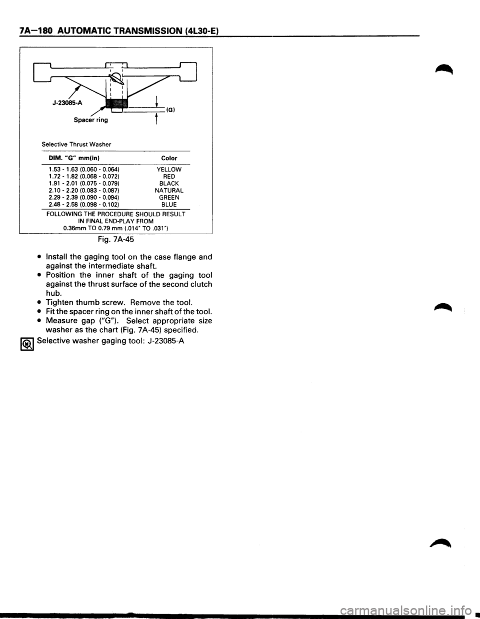
7A-180 AUTOMATIC TRANSMISSION (4L30-E)
Selective Thrust Washer
DIM. "G" mm(in)
1.53 -1.63 (0.060 -0.064} 1. 72 -1.82 (0.068 -0.072} 1.91 -2.01 (0.075 -0.079}
2.10 -2.20 (0.083 -0.087} 2.29 -2.39 (0.090 -0.094} 2.48 -2.58 (0.098 -0.1 02)
Color
YELLOW RED BLACK NATURAL GREEN BLUE
FOLLOWING THE PROCEDURE SHOULD RESULT IN FINAL END-PLAY FROM 0.36mm TO 0.79 mm (.014" TO .031")
Fig. 7A-45
• Install the gaging tool on the case flange and
against the intermediate shaft.
• Position the inner shaft of the gaging tool
against the thrust surface of the second clutch
hub.
• Tighten thumb screw. Remove the tool.
•
Fit the spacer ring on the inner shaft of the tool.
•
Measure gap ("G"). Select appropriate size
washer as the chart (Fig. 7A-45) specified.
1<&1 Selective washer gaging tool: J-23085-A
•