odometer ISUZU TROOPER 1995 Workshop Manual
[x] Cancel search | Manufacturer: ISUZU, Model Year: 1995, Model line: TROOPER, Model: ISUZU TROOPER 1995Pages: 1928
Page 18 of 1928
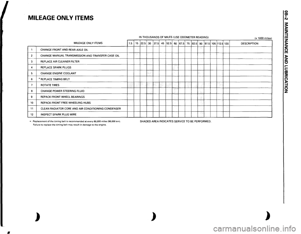
MILEAGE
ONL
V
ITEMS MILEAGE
ONLY
ITEMS
7.5
1
CHANGE
FRONT
AND
REAR AXLE
OIL
2
CHANGE
MANUAL
TRANSMISSION
AND
TRANSFER CASE
OIL
3
REPLACE AIR
CLEANER FILTER
4
REPLACE SPARK PLUGS
5
CHANGE ENGINE
COOLANT
6
*REPLACE
TIMING
BELT
7
ROT
ATE
TIRES
8
CHANGE
POWER STEERING FLUID
9
REPACK FRONT
WHEEL
BEARINGS
10
REPACK FRONT
FREE-WHEELING HUBS
11
CLEAN
RADIATOR
CORE
AND
AIR CONDITIONING CONDENSER
12
INSPECT SPARK PLUG WIRE
'
-----
* : Replacement
of the
timing
belt
is recommended
at every
60,000
miles
(96,000
km).
Failure
to replace
the timing
belt
may
result
in damage to the engine.
)
•
IN THOUSANDS
OF
MILES
(USE
ODOMETER
READING)
15 22.5
30
37.5 45 52.5
60
67.5
75
82.5
90
97.5
'
-
'---
~--·-L....
SHADED AREA
INDICATES SERVICE TO
BE
PERFORMED.
)
105
112.5
120 '-------
(x 1000
miles)
DESCRIPTION ------
)
0 ~ s: l> ~ z l> z 0 m l> z c rc m :a c; ~ 0 2
Page 19 of 1928
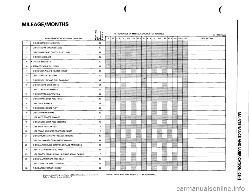
(
(
(
MILEAGE/MONTHS
rn
I ffi
IN THOUSANDS
OF
MILES
(USE
ODOMETER READING)
(x 1000
miles)
~ +~
7.5 15 22.5
30
37.5 45 52.5
60
67.5
75
82.5
90
97.5
105
112.5
120 DESCRIPTION
1
CHECK
BATTERY
FLUID
LEVEL
12
2'-'.:j:
:':
';;;;;
I '' ''
,,,,,,,,,:
[}
2
CHECK
ENGINE
COOLANT
LEVEL
12
':iti:·:
(''''/''?
'';?
,,,,,,,;.;.,.,....
,,,~~
3
CHECK
BRAKE
AND
CLUTCH
FLUID
LEVEL
12
:;:;:;:;:·:·:·.
\::':\' '\"':(\':'''''''''
:'·'·'·:·.,.,,,,
d~~~~~~-------------~
)''
'"''''{''''
'}';;o;o;;
l':':':·:o·.·o·····
4
CHECK
FLUID
LEAKS
12
•.•••..••• ,,......
,,,,,,,,,,,
5
* CHANGE
ENGINE
OIL
12
:.•••:•····
f ) : •
: ; ' {
1:':''''
6
*REPLACE
ENGINE
OIL
FILTER
12
{\::::::::;
[:(o:'.
7
CHECK
COOLING
AND
HEATER
HOSES
12
I : ' :
?
,,,.,,,,,.,:,
.. ;
! • !
•••••••••.
8
CHECK
EXHAUST
SYSTEM
12
I
~
J
:
: ••;·,·····,:·:';';·
•••::::::::::·:;.;
I ;J
., ..... .
9
CHECK
FUEL
LINE
AND
FUEL
TANK/CAP
12
10
CHECK
ENGINE
DRIVE
BELTS
24
. .
I
I
11
CHECKTIRESANDWHEELS
12
li
1:;:~:
}::,
..... ::::, .. ,::,:,:,:,·····
j
12
CHECK
STEERING
OPERATION
12
1
r ., .. ,,.,,.
·
I
13
CHECK
BRAKE
LINES
AND
HOSE
12
~
~
<
.,>
/ ':'??i'
}
J
t
''}{
14
CHECK
DISC
BRAKES
12
10
}}
UL
'I I
•....
15
CHECK
BRAKE
PEDAL
PLAY
12
I"
.. )t
16
CHECK
PARKING
BRAKE
12
li
I
17
LUBE
ACCELERATOR
LINKAGE
6
,,.:
....
I
18
CHECK
SUSPENSION
AND
STEERING
12
••·•••·•··•
19
LUBE
BODY
AND
CHASSIS
6
1''''':'''''''''''
20
LUBE
FRONT
AND
REAR
PROPELLER
SHAFT 6
{:
!: • :•••••l
21
CHECK
PROPELLER
SHAFT FLANGE
TORQUE
12
•
22
*CHECK AUTOMATIC TRANSMISSION
FLUID
12
... ,, ,....
@{I{
,,,,,,,,
ttJ
·~+---------------!
23
CHECK
AUTO
CRUISE
CONTROL
LINKAGE
AND
HOSES
12
~ .
:l
!•••:
24
CHECK
CLUTCH
LINES
AND
HOSE
12
25
LUBE
CLUTCH
PEDAL
SPRING,
BUSHING
AND
CLEVIS
PIN
6
l':":"·:"ii
26
CHECK
CLUTCH
PEDAL
FREE
PLAY
12
1/JJ(
21
cHEcK sTARTER SAFETY swiTCH 12
1/,,,,.,,,,,,,,,
,,,,,,,,,
-~~~--~~~~~~-~~~~~[============J
28
CHECK
ACCELERATOR
LINKAGE
12
m ::::::::]
!•'····
'.!
Under
severe driving conditions,
additional
maintenance
is required.
Refer to
"Severe
driving
conditions".
SHADED AREA
INDICATES
SERVICE
TO
BE PERFORMED.
s: ~ 2 -1 m 2 )> 2 n m )> 2 c rc m ::u n ~ 0 2 Q ~
Page 201 of 1928
WHEELS AND TIRES 3E-1
SECTION 3E
WHEELS AND TIRES
W CAUTION:
When fasteners are removed, always reinstall them at the same location from which they were removed.
If a fastener needs to be replaced, use the correct part number fastener for that application. If the correct
part
number fastener is not available, a fastener of equal size and strength (or stronger) may be used.
Fasteners
that are not reused, and those requiring thread locking compound, will be called out. The correct
torque value must be used when installing fasteners that require it. If the above conditions are not
followed, parts or system damage could result.
CONTENTS
General Description . . . . . . . . . . . . . . . . . . . . . . . . . . . . . . . 3 E -1 Unit Repair .......................................... 3E-7
Diagnosis ........................................... 3E-2 Tires ............................................... 3E-7
Irregular and Premature Wear ................ 3E-2 Wheels ............................................ 3E-7
Inflation of Tires ................................. 3 E- 3 General Balance Procedure ................... 3E-8
Diagnosis List. . . . . . . . . . . . . . . . . . . . . . . . . . . . . . . . . . . . 3 E- 3 Balancing Wheel and Tire ...................... 3E-8
On-Vehicle Service ................................ 3E-6 Main Data and Specifications .................... 3E-9
Wheels ............................................ 3E-6 General Specifications ......................... 3E-9
Torque Specifications .......................... 3E-9
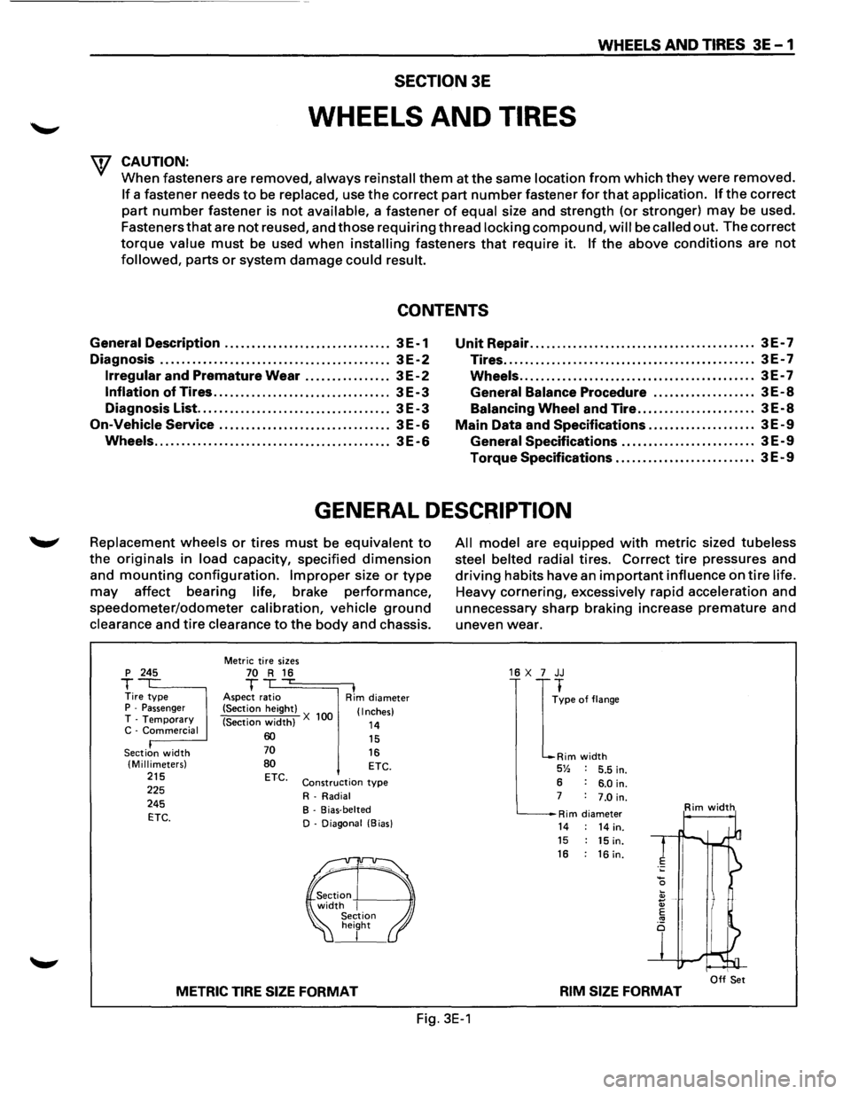
GENERAL DESCRIPTION
Replacement wheels or tires must be equivalent to
the originals in load capacity, specified dimension
and mounting configuration. Improper size or type
may affect bearing life, brake performance,
speedometer/odometer calibration, vehicle ground
clearance and tire clearance to the body and chassis.
p 245
T Tire type P -Passenger T -Temporary C -Commercial
Section
width (Millimeters) 215 225
245
ETC.
Metric tire sizes 70 R 16 T ,...
Aspect ratio I Rim diameter
(Section height)
(Section
width) X 100 (Inches)
14 60 70
80 ETC.
15
16 ETC.
Construction type
R-Radial
B - Bias-belted
D - Diagonal (Bias)
METRIC TIRE SIZE FORMAT
All model are equipped with metric sized tubeless
steel belted radial
tires. Correct tire pressures and
driving habits have an important influence on tire life.
Heavy cornering, excessively rapid acceleration and
unnecessary sharp braking increase
premature and
uneven wear.
16 X 7 JJ
I
~pe of flange
Rim width 5% 5.5 in.
6 6.0 in. 7 7.0 in.
Rim diameter Rim width
14 14 in. 15 15 in. 16 : 16 in.
I Off Set RIM SIZE FORMAT
Fig. 3E-1
Page 1484 of 1928
8-294 CHASSIS ELECTRICAL
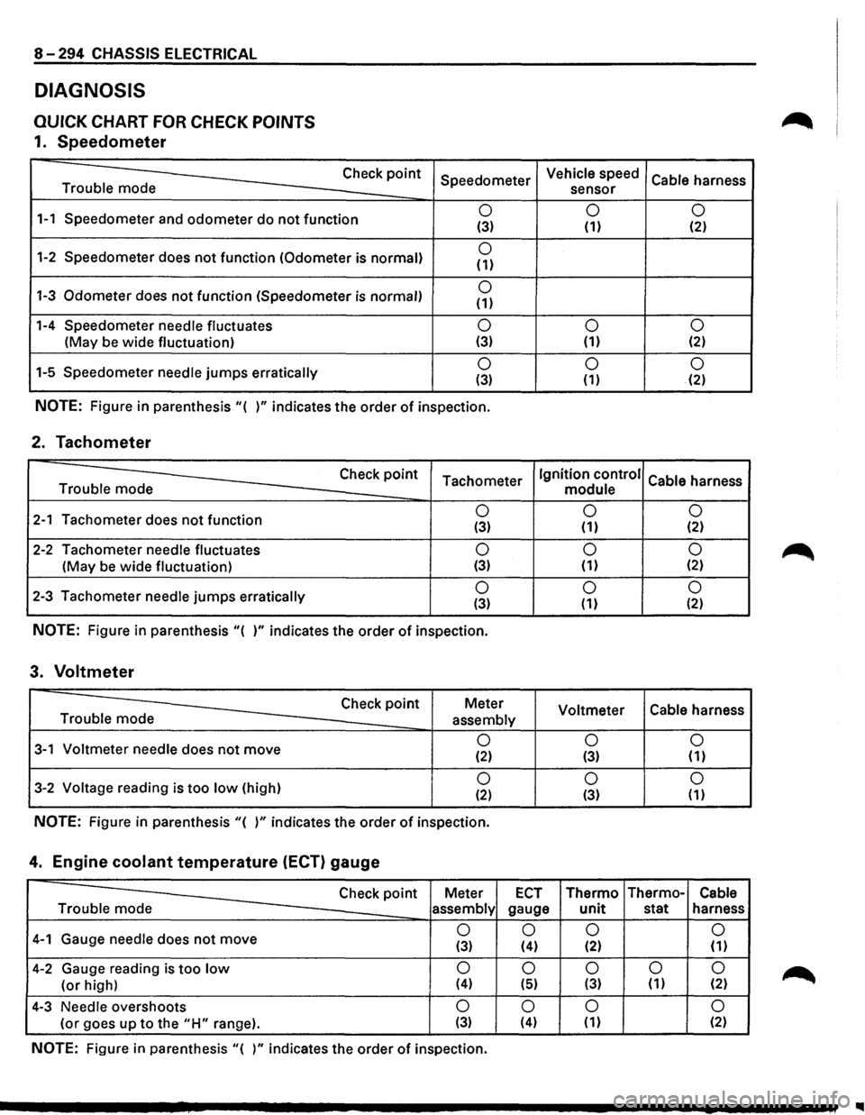
DIAGNOSIS
QUICK CHART FOR CHECK POINTS
1. Speedometer
Trouble mode Check
point
1-1 Speedometer
and odometer do not function
1-2 Speedometer does not function (Odometer is normal)
1-3 Odometer does not function (Speedometer is normal)
1-4 Speedometer needle fluctuates
(May be wide fluctuation)
1-5 Speedometer
needle jumps erratically Speedometer
0 (3)
0 (1)
0 (1)
0 (3)
0 (3)
NOTE: Figure
in parenthesis "( )" indicates the order of inspection.
2. Tachometer
Check point Tachometer Trouble mode
2-1 Tachometer does not function 0 (3)
2-2 Tachometer needle fluctuates 0
(May be wide fluctuation) (3)
2-3 Tachometer needle jumps erratically 0 (3)
NOTE: Figure in parenthesis "( )" indicates the order of inspection.
3. Voltmeter
Check point Meter
Trouble mode
assembly
3-1 Voltmeter needle does not move 0 (2)
3-2 Voltage reading is too low (high) 0 (2)
NOTE: Figure in parenthesis "( )" indicates the order of inspection.
4. Engine coolant temperature (ECT) gauge
Vehicle speed
Cable harness
sensor
0 0 (1) (2)
0
0 (1) (2)
0 0 (1) (2)
Ignition control
Cable harness
module
0 0
(1) (2)
0 0 (1) {2)
0 0 (1) (2)
Voltmeter Cable
harness
0 0 (3) (1)
0
0 (3) (1)
Check point Meter ECT Thermo Thermo-Cable
Trouble mode
assembly gauge unit stat harness
4-1 Gauge needle does not move 0
0 0
0
(3) (4) (2) (1)
4-2 Gauge reading is too low 0 0 0 0 0
(or high) (4) (5) (3) (1) (2)
4-3 Needle overshoots 0 0 0 0
(or goes up to the "H" range). (3) (4) (1) (2)
NOTE: Figure in parenthesis "( )" indicates the order of inspection.
..
Page 1486 of 1928
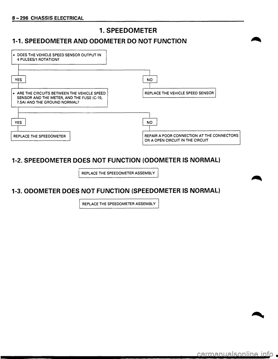
8-296 CHASSIS ELECTRICAL
1. SPEEDOMETER
1-1. SPEEDOMETER AND ODOMETER DO NOT FUNCTION
• DOES THE VEHICLE SPEED SENSOR OUTPUT IN
4 PULSES/1 ROTATION?
I
I I
YES I NO I
I
I
• ARE
THE CIRCUITS BETWEEN THE VEHICLE SPEED REPLACE
THE VEHICLE SPEED SENSOR I
SENSOR AND THE METER, AND THE FUSE (C-10,
7.5A) AND THE GROUND NORMAL?
I
j I
YES I NO I
I I
REPLACE
THE SPEEDOMETER I REPAIR A POOR CONNECTION AT THE CONNECTORS
OR A OPEN CIRCUIT IN THE CIRCUIT
1-2. SPEEDOMETER DOES NOT FUNCTION (ODOMETER IS NORMAL)
I REPLACE THE SPEEDOMETER ASSEMBLY I
1-3. ODOMETER DOES NOT FUNCTION (SPEEDOMETER IS NORMAL)
I REPLACE THE SPEEDOMETER ASSEMBLy I
..
Page 1508 of 1928
8-318 CHASSIS ELECTRICAL
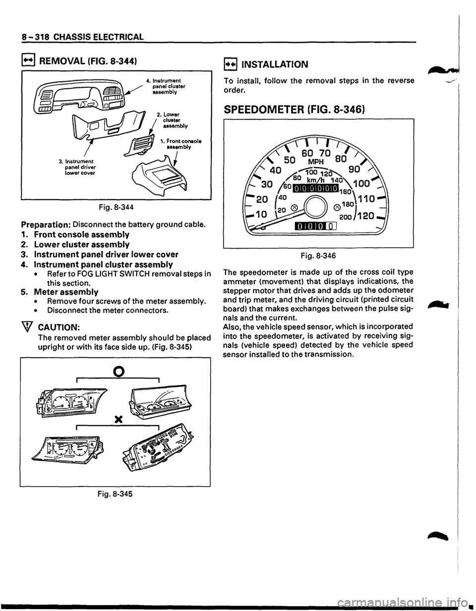
B REMOVAL (FIG. 8-344)
3. Instrument
panel driver lower cover
Fig. 8-344
4. Instrument
panel cluster
assembly
Preparation: Disconnect the battery ground cable.
1. Front console assembly
2. Lower cluster assembly
3. Instrument panel driver lower cover
4. Instrument panel cluster assembly
• Refer to FOG LIGHT SWITCH removal steps in
this section.
5. Meter assembly
• Remove four screws of the meter assembly.
•
Disconnect the meter connectors.
W CAUTION:
The removed meter assembly should be placed
upright or with its face side up. (Fig. 8-345)
0
)(
Fig. 8-345
B INSTALLATION
To install, follow the removal steps in the reverse
order.
SPEEDOMETER (FIG. 8-346)
Fig. 8-346
The speedometer is made up
of the cross coil type
ammeter (movement)
that displays indications, the
stepper
motor that drives and adds up the odometer
and
trip meter, and the driving circuit (printed circuit
board) that makes exchanges between the
pulse sig
nals and the current.
Also, the vehicle speed sensor, which is incorporated
into the speedometer, is activated
by receiving sig
nals (vehicle speed) detected by the vehicle speed
sensor
installed to the transmission.
•
Page 1509 of 1928
![ISUZU TROOPER 1995 Workshop Manual (1!] ON-VEHICLE SERVICE
"-"" Check the meter display accuracy and the operation
of the odometer with the speedometer tester.
\f CAUTION:
Inappropriate tire inflation may affect the accu
rac](/img/61/57183/w960_57183-1508.png "ISUZU TROOPER 1995 Workshop Manual (1!] ON-VEHICLE SERVICE
\"-\"\" Check the meter display accuracy and the operation
of the odometer with the speedometer tester.
\f CAUTION:
Inappropriate tire inflation may affect the accu
rac")
(1!] ON-VEHICLE SERVICE
"-"" Check the meter display accuracy and the operation
of the odometer with the speedometer tester.
\f CAUTION:
Inappropriate tire inflation may affect the accu
racy
of the odometer.
(To
conductthis test, refer to the tester manufac
turer's instruction manual.)
IGN GND
SEN
CHASSIS ELECTRICAL 8-319
(MPH)
Tester display speed Meter
display permissible
level
20 18.3-21.7
40 38.3-41.7
60 58.3-61.7
80 78.8-82.8
100 98.8-102.8
120 118.5-123.1
NOTE: Since the meter display permissible levels
above are specifications solely
for the
meter,
they are to be used as reference
values when conducting on-vehicle service.
~ INDIVIDUAL INSPECTION
I t!!.l Remove the speedometer from the meter
assembly and measure the resistance and the
current consumption between each terminal.
(Fig. 8-347)
Replace the speedometer
when the result of
inspection is found abnormal.
Resistance value
Red(+) Black(-) Black(-) Red(+)
IGN GND IGN GND IGN-GND 00 30.6-37.4k
SEN GND SEN GND SEN-GND 28.8-35.2k 00
4P GND 4P GND 4P-GND 13.5 -16.5k 00
Note: Use the
analog type circuit tester (range: x 1k)
Current value
Terminal
symbol
IGN-GND
~ 8
Current
consumption
85 ± 15mA Remarks
(when
12 ± 1V No signal input
applied)
Note: 1. Use the analog type circuit tester.
2. Since the current consumption fluctuates
when the source voltage varies, check
to
be sure that the voltage applied is 12V ± 1 V.
Fig. 8-347