clutch ISUZU TROOPER 1995 Repair Manual
[x] Cancel search | Manufacturer: ISUZU, Model Year: 1995, Model line: TROOPER, Model: ISUZU TROOPER 1995Pages: 1928
Page 882 of 1928
7A-10 AUTOMATIC TRANSMISSION (4L30-E)
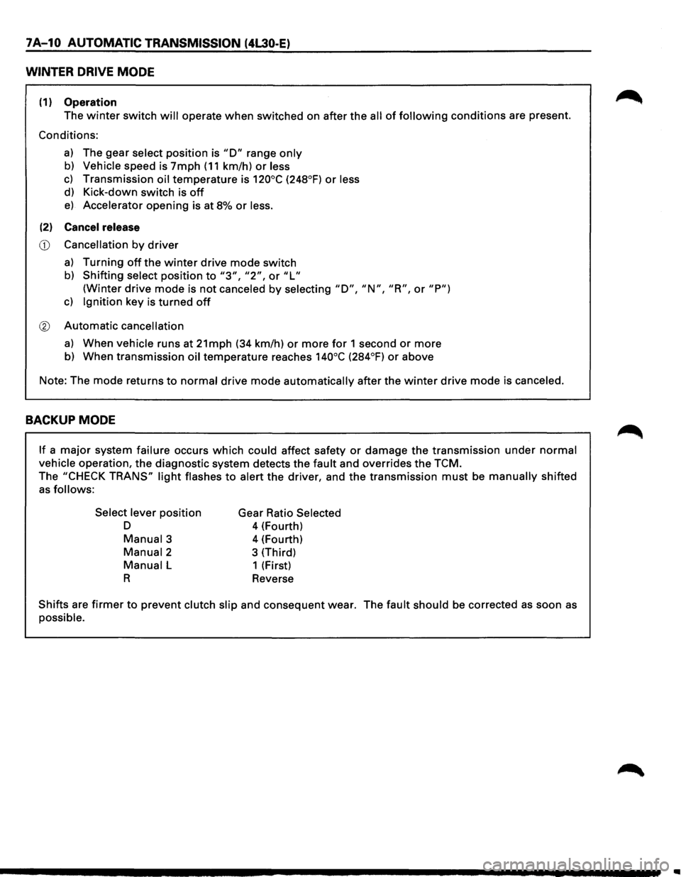
WINTER DRIVE MODE
(1) Operation
The winter switch will operate when switched on after the all of following conditions are present.
Conditions:
a) The gear select position is "D" range only
b) Vehicle speed is 7mph (11 km/h) or less
c) Transmission oil temperature is 120°C (248°F) or less
d) Kick-down switch is off
e) Accelerator opening is at 8% or less.
(2) Cancel release
CD Cancellation by driver
a) Turning off the winter drive mode switch
b) Shifting select position to "3", "2", or "L"
(Winter drive mode is not canceled by selecting "D", "N", "R", or "P")
c) Ignition key is turned off
® Automatic cancellation
a) When vehicle runs at 21mph (34 km/h) or more for 1 second or more
b) When transmission oil temperature reaches 140°C (284°F) or above
Note: The mode returns
to normal drive mode automatically after the winter drive mode is canceled.
BACKUP MODE
If a major system failure occurs which could affect safety or damage the transmission under normal
vehicle operation, the diagnostic system detects the fault and overrides the TCM.
The "CHECK TRANS" light flashes to alert the driver, and the transmission must be manually shifted
as follows:
Select lever
position
D
Manual3
Manual2
Manual L
R
Gear Ratio Selected
4 (Fourth)
4 (Fourth)
3 (Third)
1 (First)
Reverse
Shifts are firmer to prevent clutch slip and consequent wear. The fault should be corrected as soon as
possible.
Page 883 of 1928

AUTOMATIC TRANSMISSION (4L30-E) 7 A-11
FUNCTIONS OF INPUT /OUTPUT COMPONENTS
Components Function
Speed sensor
Senses rotation
of output shaft and feeds the data to Transmission
(fixed
to transmission (T/M)) Control Module (TCM)
Throttle Senses the extent of throttle valve opening and the speed of the throttle
position sensor (TPS) valve lever motion to open the valve and feeds the data to TCM (fed to
(fixed to engine)
Engine Control Module (ECM) also)
I
Brake Switch (SW) Senses whether the driver has pressed the brake pedal or not and feeds
N (fixed
to brake pedal) the
information to TCM
p Kick-down SW (fixed to Senses whether the driver has pushed the accelerator pedal fully or not
u accelerator pedal) and feeds the information to TCM
T Mode
SW (fixed to T/M) Senses the select lever position and feeds the information to TCM
s Power drive SW Senses whether the driver has selected the power mode and feeds the
I (fixed to front console) information to TCM
G T/M
oil temp. sensor
Senses the T/M oil temperature and feeds the data to TCM
N Engine
coolant Senses the engine cooling water temperature and feeds the data to TCM
A temperature
SW (feeds the signal from ECM)
L
Engine speed
signal Feeds the signals monitoring engine speed to TCM from Ignition Control
Module
(fed to ECM also)
Air conditioning Senses whether the air conditioner has been switched on or not and
information feeds the information
to TCM
On-board diagnostic
input By monitoring the Ground (GND), the location of failure is shown on the
T/M
monitor lamp ("CHECK TRANS") by flashing the diagnostic trouble
code
Winter switch
Senses whether the driver has selected the winter mode, and feeds the
(fixed
to front console) information to TCM
Cruise
controller Downshift takes place when Overdrive OFF signal is received from auto
(Overdrive
OFF signal) cruise control unit
Shift
solenoid Selects shift point and gear position suited to the vehicle running con-s 1-2/3-4, 2-3
dition on the basis of TCM output 0 Band apply solenoid
Controls oil flow suited to the vehicle running condition on the basis of L
E TCM output
0 N
Torque
Converter Controls clutch engagement/disengagement suited to the vehicle
u 0 Clutch solenoid running condition on the basis of TCM output
T I Force motor Adjusts the oil pump delivery pressure to line pressure suited to the p D
(Pressure regulator vehicle running condition on the basis of TCM output u valve) T
Power drive mode lamp
Informs the driver whether the vehicle is in power mode or not
s Winter drive mode lamp Informs the driver whether the vehicle is in winter mode or not
I T/M monitor lamp Informs the driver of failure in the system. It also displays the self diagnosis
G
("CHECK TRANS") code.
N Data Link Connector
(DLC) When connected with TECH 1 or tester, can communicate the data for A
L function
check, etc. (fed to ECM also). When TECH 1 is not connected, can
communicate the
signal for torque management with ECM.
Self-diagnosis connector
When short-circuited with the bipolar connector, the T/M monitor lamp
displays
a failure by code.
ATF warning
lamp Lights when ATF oil temperature rises.
ABS signal When the select lever is at "Reverse" or "L" range, sends a signal to the
ABS controller as one of the ABS control conditions.
Page 884 of 1928
7A-12 AUTOMATIC TRANSMISSION (4L30-E)
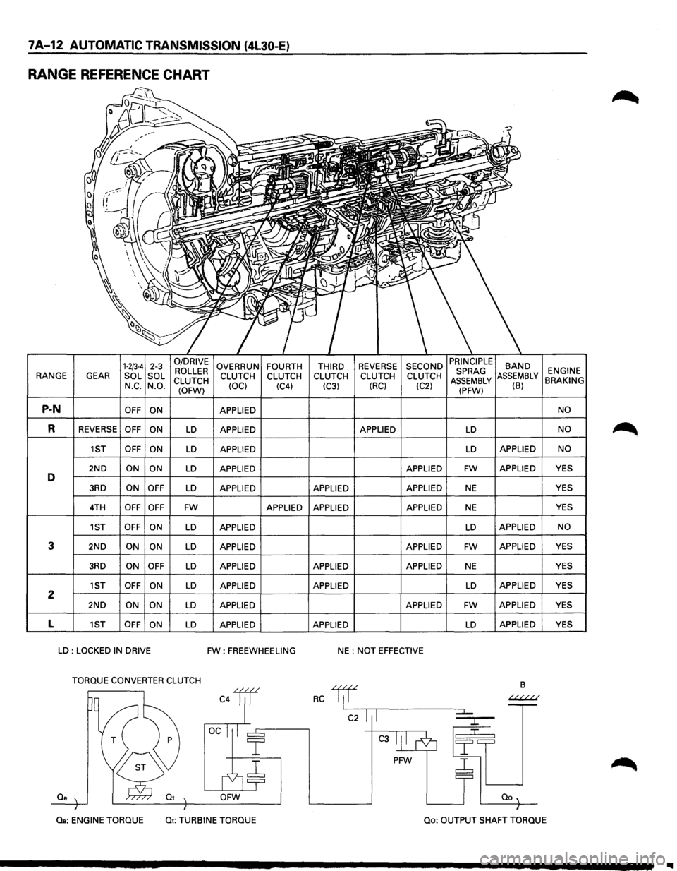
RANGE REFERENCE CHART
1-2/3-4 2-3 0/DRIVE OVERRUN FOURTH THIRD REVERSE SECOND BAND ROLLER ENGINE RANGE
GEAR SOL
SOL
CLUTCH CLUTCH
CLUTCH CLUTCH CLUTCH CLUTCH MBLY BRAKING N_c. N.O.
(OFW) (OCl
(C4)
(C3) (RC)
(C2) (B)
P-N OFF
ON APPLIED NO
R REVERSE OFF
ON LD APPLIED APPLIED LD NO
1ST OFF
ON LD APPLIED LD APPLIED NO
2ND ON ON LD APPLIED APPLIED FW APPLIED YES D 3RD ON
OFF LD APPLIED APPLIED APPLIED NE YES
4TH OFF OFF FW APPLIED APPLIED APPLIED NE YES
1ST OFF ON
LD APPLIED LD APPLIED NO
3 2ND ON ON LD APPLIED APPLIED FW APPLIED
YES
3RD ON OFF LD APPLIED APPLIED APPLIED NE YES
1ST OFF
ON LD APPLIED APPLIED LD APPLIED YES 2 2ND ON
ON LD APPLIED APPLIED FW APPLIED YES
L 1ST OFF
ON LD APPLIED APPLIED LD APPLIED
YES
LD : LOCKED IN DRIVE FW: FREEWHEELING NE : NOT EFFECTIVE
TORQUE CONVERTER CLUTCH
B
C4lil RC 1/f ~
C2 I I
C3
PFW ~
Qe OFW
Qe: ENGINE
TORQUE Qt: TURBINE TORQUE Qo: OUTPUT SHAFT TORQUE
Page 885 of 1928
AUTOMATIC TRANSMISSION (4L30-E) 7A-13
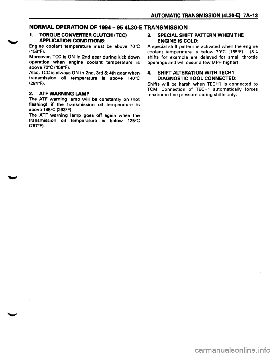
NORMAL OPERATION OF 1994-95 4L30-E TRANSMISSION
1. TORQUE CONVERTER CLUTCH (TCC)
APPLICATION CONDITIONS:
Engine coolant temperature must be above 70°C
(158°F).
Moreover, TCC is ON in 2nd gear during kick down
operation when engine coolant temperature is
above
70°C (158°F).
Also,
TCC is always ON in 2nd, 3rd & 4th gear when
transmission oil temperature is above 140°C
(284°F).
2. ATF WARNING LAMP
The ATF warning lamp will be constantly on (not
flashing) if the transmission oil temperature is
above
145°C (293°F).
The ATF warning lamp goes off again when the
transmission
oil temperature is below 125°C
(257°F).
3. SPECIAL SHIFT PATTERN WHEN THE
ENGINE IS COLD:
A special shift pattern is activated when the engine
coolant temperature is below 70°C (158°F). (3-4
shifts
for example are delayed for small throttle
openings and will occur a few MPH higher)
4. SHIFT ALTERATION WITH TECH1
DIAGNOSTIC TOOL CONNECTED:
Shifts will be harsh when TECH1 is connected to
TCM: Connection of TECH1 automatically forces
maximum line pressure during shifts only.
Page 896 of 1928
7 A-24 AUTOMATIC TRANSMISSION (4l30-E)
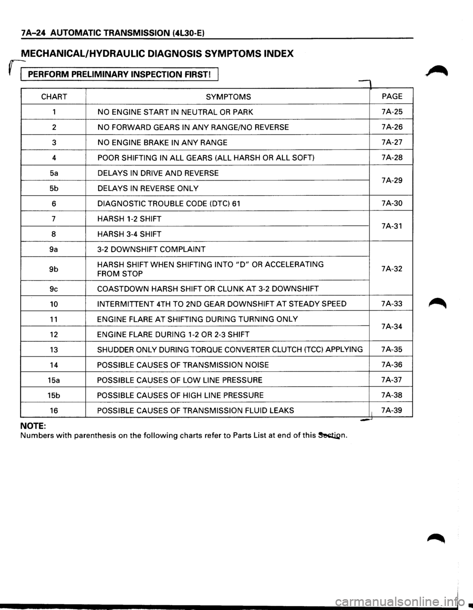
MECHANICAL/HYDRAULIC DIAGNOSIS SYMPTOMS INDEX
rr PERFORM PRELIMINARY INSPECTION FIRST! , -
CHART SYMPTOMS PAGE
1
NO ENGINE START IN NEUTRAL OR PARK 7A-25
2
NO FORWARD GEARS IN ANY RANGE/NO REVERSE 7A-26
3
NO ENGINE BRAKE IN ANY RANGE 7A-27
4
POOR SHIFTING IN ALL GEARS (ALL HARSH OR ALL SOFT) 7A-28
Sa DELAYS IN DRIVE AND REVERSE 7A-29
5b DELAYS
IN REVERSE ONLY
6 DIAGNOSTIC TROUBLE CODE (DTC) 61 7A-30
7 HARSH 1-2
SHIFT 7A-31
8 HARSH 3-4
SHIFT
9a 3-2 DOWNSHIFT
COMPLAINT
9b HARSH SHIFT WHEN SHIFTING INTO "D" OR ACCELERATING 7A-32 FROM STOP
9c COASTDOWN HARSH SHIFT OR CLUNK AT 3-2 DOWNSHIFT
10 INTERMITTENT 4TH TO 2ND GEAR DOWNSHIFT AT STEADY SPEED 7A-33
11 ENGINE FLARE AT SHIFTING
DURING TURNING ONLY 7A-34
12 ENGINE FLARE DURING 1-2 OR 2-3 SHIFT
13 SHUDDER ONLY DURING TORQUE CONVERTER CLUTCH (TCC) APPLYING 7A-35
14
POSSIBLE CAUSES OF TRANSMISSION NOISE 7A-36
15a
POSSIBLE CAUSES OF LOW LINE PRESSURE 7A-37
15b
POSSIBLE CAUSES OF HIGH LINE PRESSURE 7A-38
16
POSSIBLE CAUSES OF TRANSMISSION FLUID LEAKS It 7A-39
= -NOTE:
Numbers with parenthesis on the following charts refer to Parts List at end of this ~n.
•
Page 898 of 1928
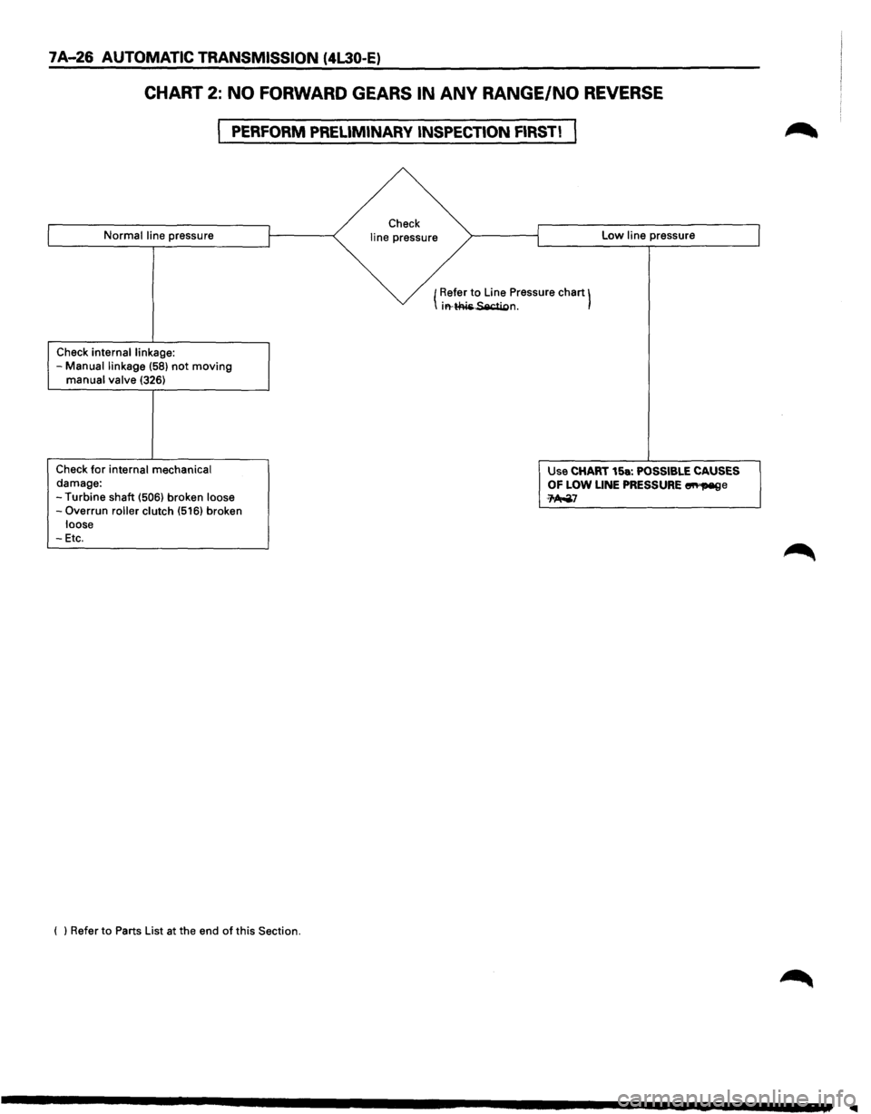
7 A-26 AUTOMATIC TRANSMISSION (4L30-E)
CHART 2: NO FORWARD GEARS IN ANY RANGE/NO REVERSE
PERFORM PRELIMINARY INSPECTION FIRST!
Normal line pressure
Check
internal linkage: -Manual linkage (58) not moving manual valve (326)
Check for internal mechanical damage:
-Turbine shaft (506) broken loose -Overrun roller clutch (516) broken loose -Etc.
( l Refer to Parts List at the end of this Section. Check
line pressure Low line pressure
( Refer
to Line
Pressure chart) irt·~~n.
Use CHART 15a: POSSIBLE CAUSES OF LOW LINE PRESSURE ~e ~7
Page 899 of 1928
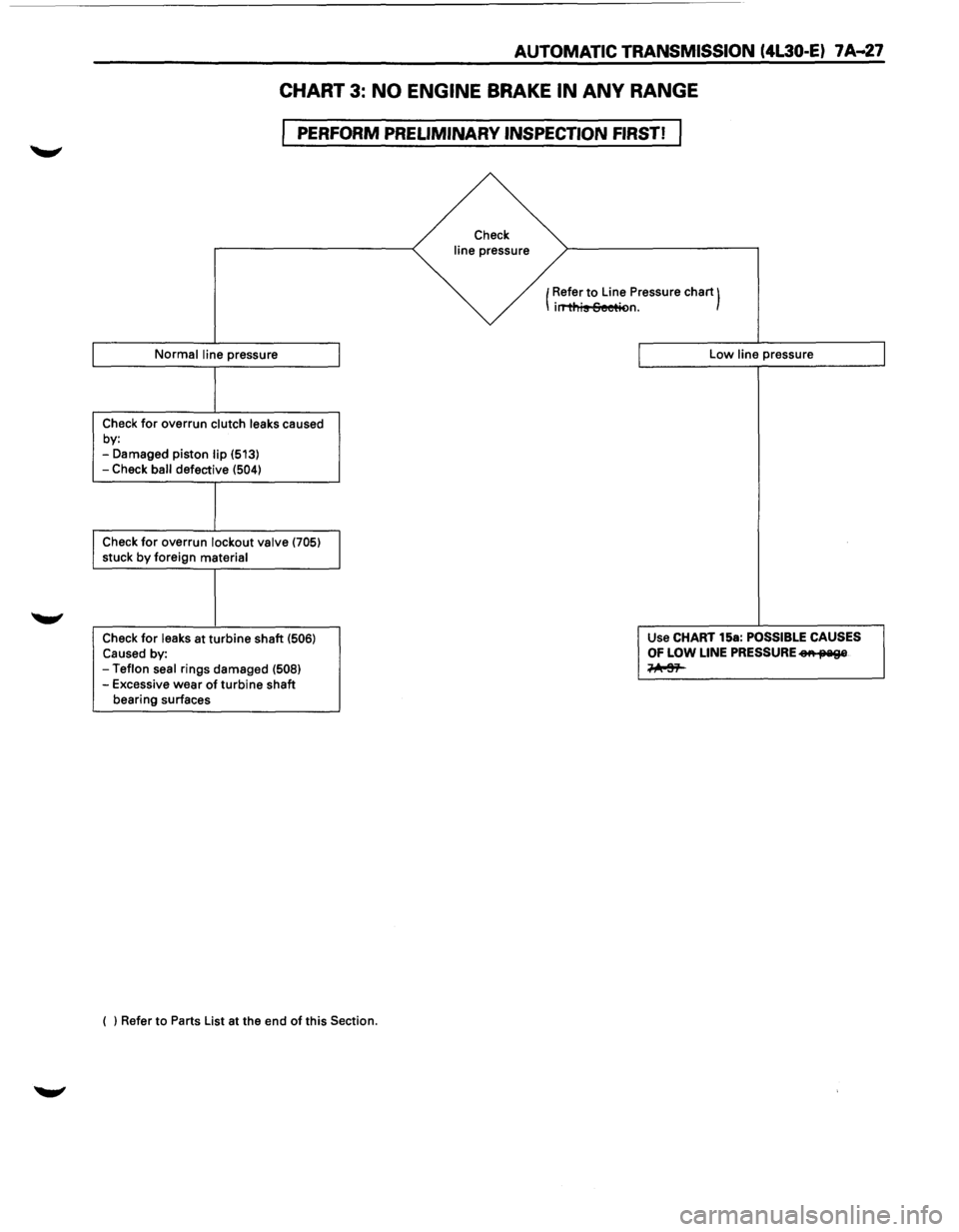
AUTOMATIC TRANSMISSION (4l30-E) 7 A--27
CHART 3: NO ENGINE BRAKE IN ANY RANGE
PERFORM PRELIMINARY INSPECTION FIRST!
Normal line pressure
Check for overrun clutch leaks caused
by:
-Damaged piston lip (513)
-Check ball defective (504)
Check for overrun lockout valve (705) stuck by foreign material
Check
for leaks at turbine shaft (506) Caused by: -Teflon seal rings damaged (508) -Excessive wear of turbine shaft
bearing surfaces
( ) Refer to Parts List at the end
of this Section.
Check
line pressure
(Refer
to Line
Pressure chart) irT'ti'lis Seetit>n.
Low line pressure
Use CHART 15a:
POSSIBLE CAUSES
OF LOW LINE PRESSURE eA fJ'Iil9&
~
Page 900 of 1928
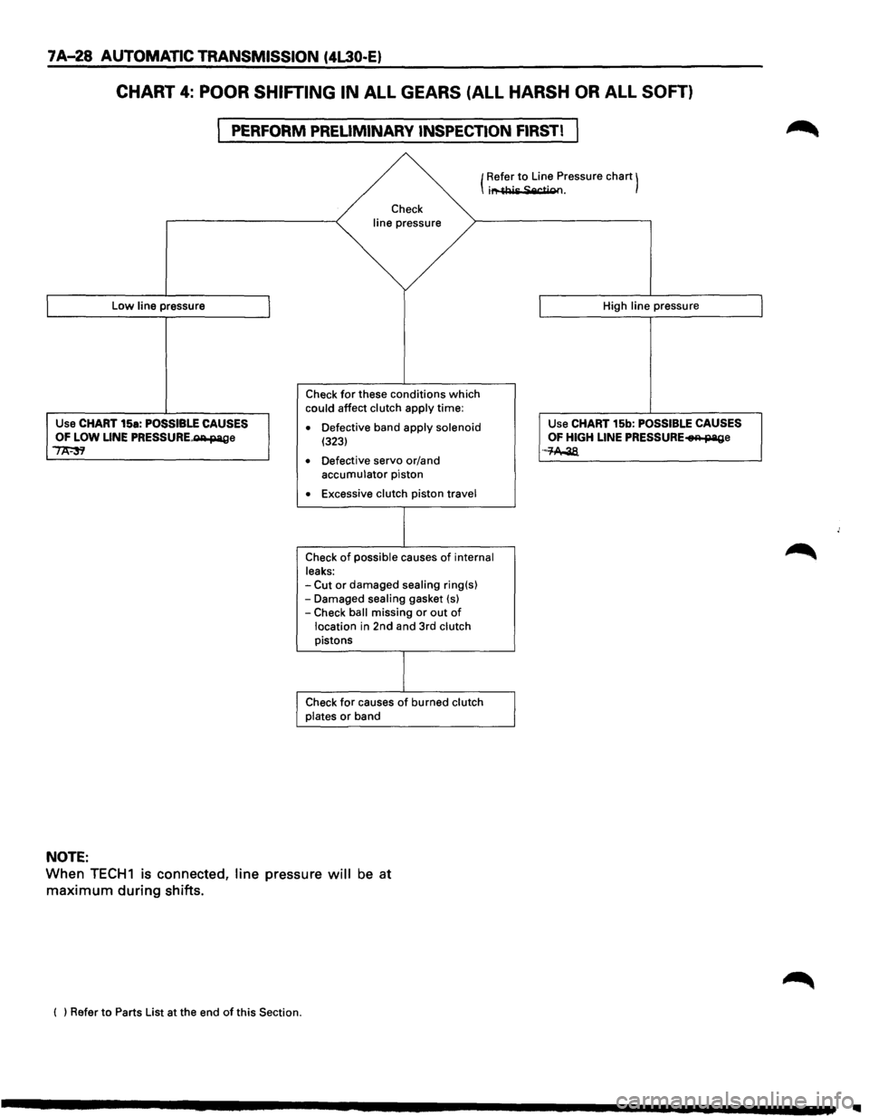
7A-28 AUTOMATIC TRANSMISSION (4L30-E)
CHART 4: POOR SHIFTING IN ALL GEARS (ALL HARSH OR ALL SOFT)
PERFORM PRELIMINARY INSPECTION FIRST!
Low line pressure
Use CHART 15a: POSSIBLE CAUSES OF LOW LINE PRESSURE~e ~
NOTE:
(Refer to Line
Pressure chart) i""~Ais Sec+ioo.
Check
line
pressure
Check for these conditions which could affect clutch apply time:
• Defective band apply solenoid (323)
• Defective servo or/and accumulator piston
• Excessive clutch piston travel
Check
of possible causes of internal
leaks:
-Cut or damaged sealing ring(s) -Damaged sealing gasket {s) -Check ball missing or out of
location in 2nd and 3rd clutch pistons
Check for causes of burned clutch
plates or band High
line pressure
Use CHART 15b: POSSIBLE
CAUSES OF HIGH LINE PRESSURE~e ·-M-38.
When TECH1 is connected, line pressure will be at
maximum during shifts.
( ) Refer to Parts List at the end of this Section.
Page 902 of 1928
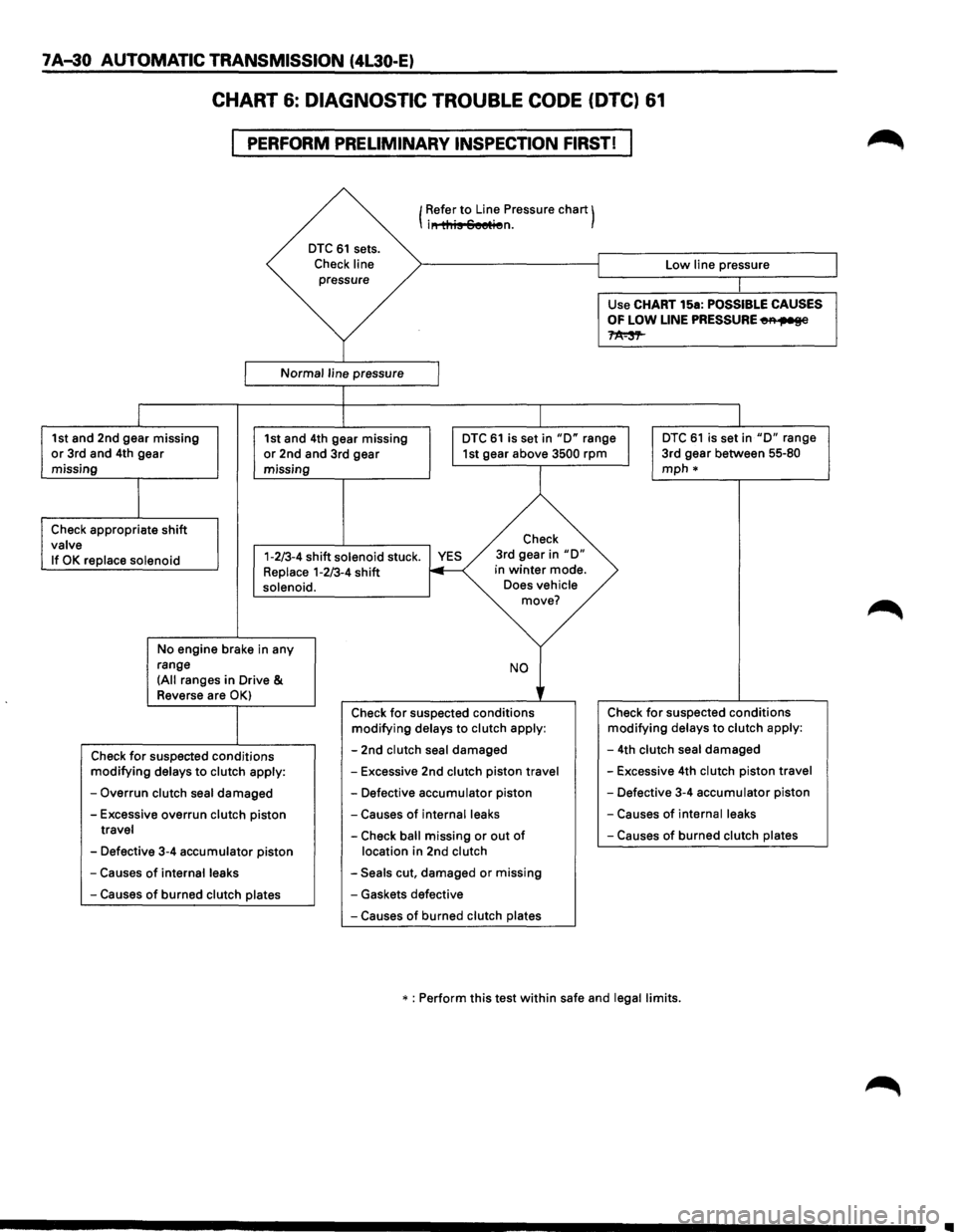
7 A-30 AUTOMATIC TRANSMISSION (4L30-E)
CHART 6: DIAGNOSTIC TROUBLE CODE (DTC) 61
PERFORM PRELIMINARY INSPECTION FIRST!
I
I
DTC 61 sets.
Check line pressure
Normal line pressure
1 Refer to Line Pressure chart) i" this Seetien.
J
Low line pressure
Use
CHART 15a: POSSIBLE CAUSES
OF LOW LINE PRESSURE~
~
1st and 2nd gear missing or 3rd and 4th gear
missing 1st
and 4th gear missing or 2nd and 3rd gear
missing I
DTC 61 is set in "D" range I 1st gear above 3500 rpm
DTC 61 is set in "D" range
3rd gear between 55-80
mph*
I
Check appropriate shift valve Check
If
OK replace solenoid 1-2/3-4 shift solenoid stuck. YES Replace 1-2/3-4 shift 3rd
gear in
"D" in winter mode.
solenoid.
No engine brake in any
range
(All ranges in Drive &
Reverse are OK)
Check for suspected conditions modifying delays to clutch apply:
-Overrun clutch seal damaged
-Excessive overrun clutch piston travel
-Defective 3-4 accumulator piston
-Causes of internal leaks
-Causes of burned clutch plates
Does vehicle move?
NO
' Check for suspected conditions modifying delays to clutch apply:
-2nd clutch seal damaged
-Excessive 2nd clutch piston travel
-Defective accumulator piston
-Causes of internal leaks
-Check ball missing or out of
location in 2nd clutch
-Seals cut, damaged or missing
- Gaskets defective
-Causes of burned clutch plates Check
for suspected
conditions modifying delays to clutch apply:
-4th clutch seal damaged
-Excessive 4th clutch piston travel
-Defective 3-4 accumulator piston
-Causes of internal leaks
-Causes of burned clutch plates
* : Perform this test within safe and legal limits.
..
Page 907 of 1928
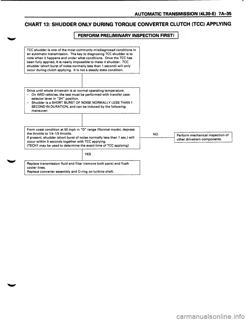
AUTOMATIC TRANSMISSION (4L30-E) 7 A-35
CHART 13: SHUDDER ONLY DURING TORQUE CONVERTER CLUTCH (TCC) APPLYING
PERFORM PRELIMINARY INSPECTION FIRST!
TCC shudder is one of the most commonly misdiagnosed conditions in
an automatic transmission. The key to diagnosing TCC shudder is to note when it happens and under what conditions. Once the TCC has
been fully applied, it is nearly impossible to make it shudder. TCC shudder {short burst of noise normally less than 1 second) will only
occur during clutch applying. It is not a steady state condition.
Drive
until whole drivetrain is at normal operating temperature.
-On 4WD vehicles, the test must be performed with transfer case selector lever in "2H" position.
- Shudder is a SHORT BURST OF NOISE NORMALLY LESS THAN 1
SECOND IN DURATION, and can be induced by the following maneuver:
From coast condition at
50 mph in "D" range {Normal mode), depress
the throttle to 1/4-1/3 throttle. If present, shudder {short burst of noise normally less than 1 sec.) will occur within 5 seconds together with TCC applying. {TECH1 may be used to determine the exact time of TCC applying)
YES
Replace transmission fluid and filter {remove both pans) and flush
cooler lines.
Replace
converter assembly and 0-ring on turbine shaft.
,__ __ N_o ___ ---<1 Perform mechanical inspection of I j other drivetrain components.