automatic transmission fluid ISUZU TROOPER 1995 Workshop Manual
[x] Cancel search | Manufacturer: ISUZU, Model Year: 1995, Model line: TROOPER, Model: ISUZU TROOPER 1995Pages: 1928
Page 14 of 1928
OA-10 GENERAL INFORMATION
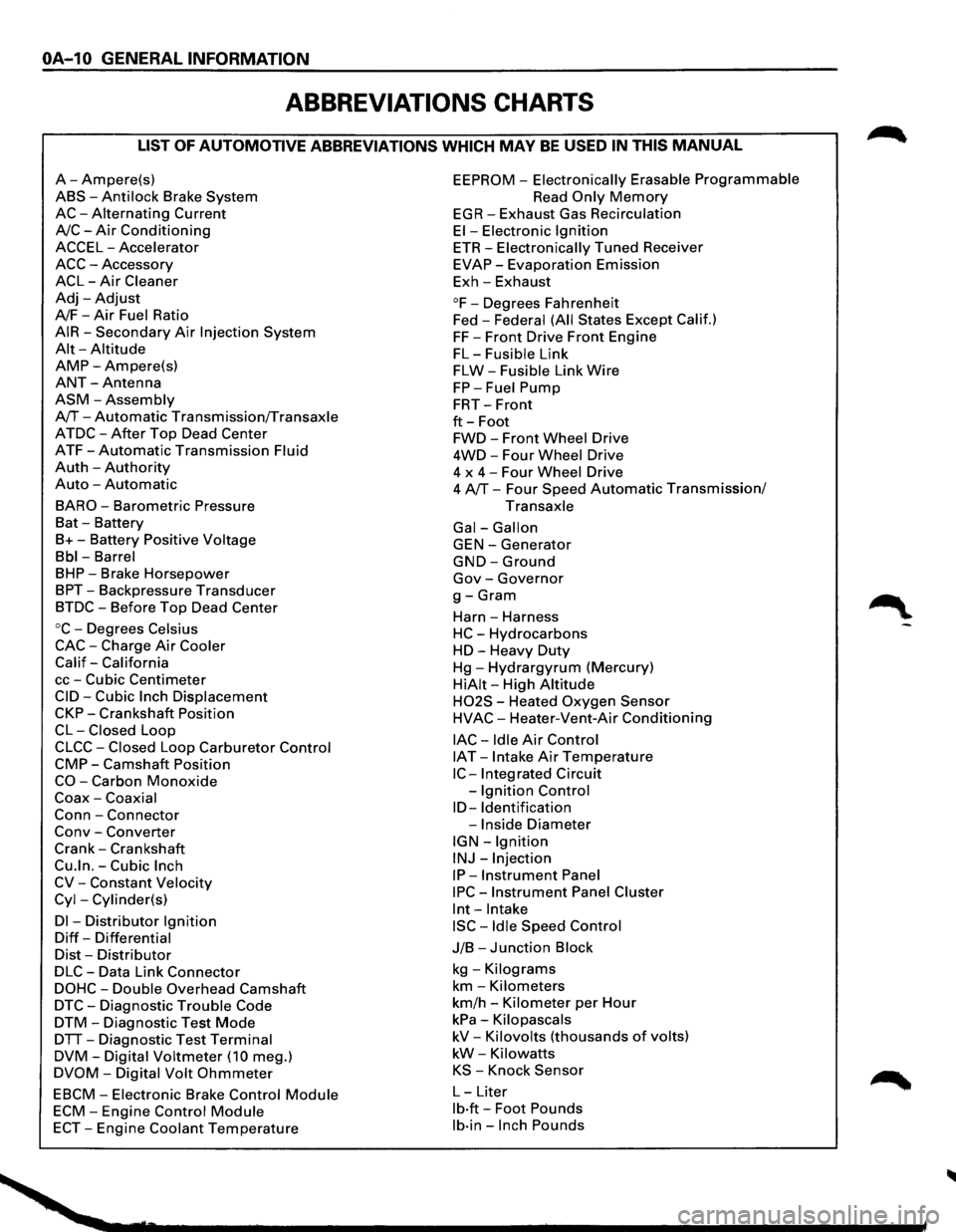
ABBREVIATIONS CHARTS
LIST OF AUTOMOTIVE ABBREVIATIONS WHICH MAY BE USED IN THIS MANUAL
A-Ampere(s)
ABS-Anti lock Brake System
AC-Alternating Current
A/C-Air Conditioning
ACCEL-Accelerator
ACC-Accessory
ACL-Air Cleaner
Adj-Adjust
A/F-Air Fuel Ratio
AIR-Secondary Air Injection System
Alt-Altitude
AMP-Ampere(s)
ANT-Antenna
ASM-Assembly
A/T-Automatic Transmission/Transaxle
ATDC-After Top Dead Center
ATF-Automatic Transmission Fluid
Auth -Authority
Auto -Automatic
BARO-Barometric Pressure
Bat -Battery
B+-Battery Positive Voltage
Bbl-Barrel
BHP-Brake Horsepower
BPT-Backpressure Transducer
BTDC-Before Top Dead Center
oc-Degrees Celsius
CAC-Charge Air Cooler
Calif-California
cc-Cubic Centimeter
CID-Cubic Inch Displacement
CKP-Crankshaft Position
CL-Closed Loop
CLCC-Closed Loop Carburetor Control
CMP-Camshaft Position
CO-Carbon Monoxide
Coax-Coaxial
Conn-Connector
Conv -Converter
Crank-Crankshaft
Cu.ln.-Cubic Inch
CV-Constant Velocity
Cyl-Cylinder(s)
Dl -Distributor Ignition
Diff-Differential
Dist-Distributor
DLC-Data Link Connector
DOHC-Double Overhead Camshaft
DTC-Diagnostic Trouble Code
DTM-Diagnostic Test Mode
DTT-Diagnostic Test Terminal
DVM-Digital Voltmeter (10 meg.)
DVOM-Digital Volt Ohmmeter
EBCM-Electronic Brake Control Module
ECM-Engine Control Module
ECT-Engine Coolant Temperature
EEPROM -Electronically Erasable Programmable
Read Only Memory
EGR-Exhaust Gas Recirculation
El-Electronic Ignition
ETR-Electronically Tuned Receiver
EVAP-Evaporation Emission
Exh-Exhaust
°F-Degrees Fahrenheit
Fed -
Federal (All States Except Calif.)
FF-Front Drive Front Engine
FL-Fusible Link
FLW-Fusible Link Wire
FP-Fuel Pump
FRT-Front
ft-Foot
FWD-Front Wheel Drive
4WD-Four Wheel Drive
4 x
4-Four Wheel Drive
4 A/T-Four Speed Automatic Transmission/
Transaxle
Gal-Gallon
GEN-Generator
GND-Ground
Gov-Governor
g-Gram
Harn -Harness
HC-Hydrocarbons
HD-Heavy Duty
Hg-Hydrargyrum (Mercury)
HiAit-High Altitude
H02S - Heated Oxygen Sensor
HVAC-Heater-Vent-Air Conditioning
lAC-Idle Air Control
IAT -Intake Air Temperature
IC-Integrated Circuit
-
Ignition Control
ID-Identification
-Inside Diameter
IGN-Ignition
INJ-Injection
IP-Instrument Panel
IPC-Instrument Panel Cluster
lnt-Intake
ISC-Idle Speed Control
J/B-Junction Block
kg -Kilograms
km-Kilometers
km/h -Kilometer per Hour
kPa-Kilopascals
kV-Kilovolts (thousands of volts)
kW-Kilowatts
KS -Knock Sensor
L-Liter
lb·ft-Foot Pounds
lb·in-Inch Pounds
Page 17 of 1928
MAINTENANCE AND LUBRICATION OB-1
SECTION 08
MAINTENANCE AND LUBRICATION
CONTENTS
Maintenance Schedule List . . . . . . . . . . . . 08-1
Explanation of Complete Vehicle
Mai-ntenance Schedule . . . . . . . . . . . . . . 08-4
Recommended
Fluids and Lubricants . . . . 08-8
Lubricant Viscosity Chart ............... 08-9
Recommended Liquid Gasket
........... 08-11
Recommended Thread Locking Agents ... 08-11
Maintenance Service Data .............. 08-12
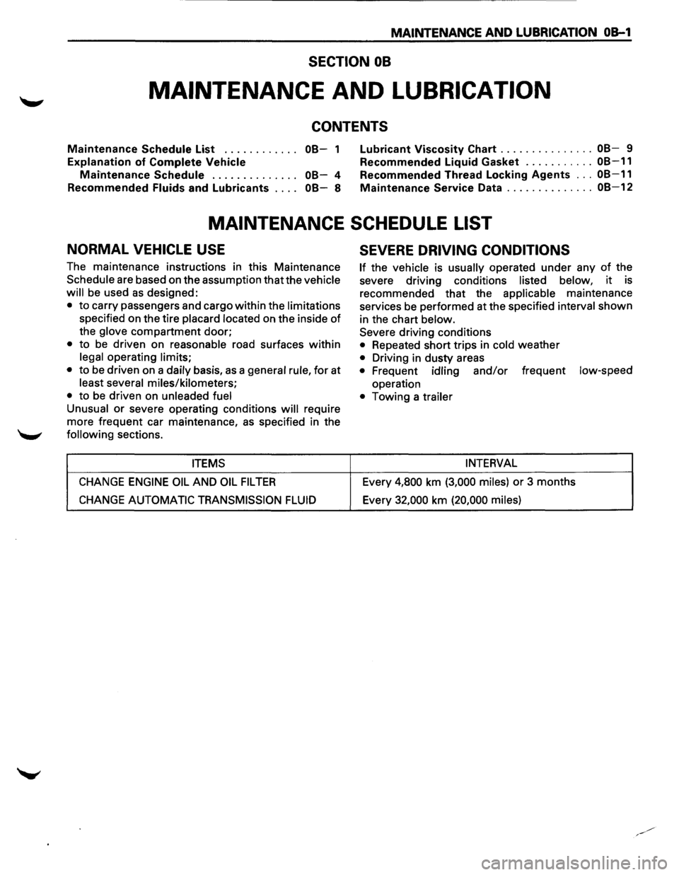
MAINTENANCE SCHEDULE LIST
NORMAL VEHICLE USE
The maintenance instructions in this Maintenance
Schedule are based on the assumption that the vehicle
will
be used as designed:
• to carry passengers and cargo within the limitations
specified on the tire placard located on the inside of
the glove compartment door;
• to be driven on reasonable road surfaces within
legal operating limits;
•
to be driven on a daily basis, as a general rule, for at
least several miles/kilometers;
•
to be driven on unleaded fuel
Unusual
or severe operating conditions will require
more frequent car maintenance,
as specified in the
following sections.
ITEMS
CHANGE ENGINE OIL AND OIL FIL TEA
CHANGE AUTOMATIC TRANSMISSION FLUID
SEVERE DRIVING CONDITIONS
If the vehicle is usually operated under any of the
severe driving conditions
listed below, it is
recommended that the
applicable maintenance
services be performed at the specified
interval shown
in the chart
below.
Severe driving conditions
• Repeated short trips in cold weather
• Driving in dusty areas
• Frequent idling and/or frequent low-speed
operation
• Towing a trailer
INTERVAL
Every 4,800 km (3,000 miles) or 3 months
Every
32,000 km (20,000 miles)
Page 19 of 1928
(
(
(
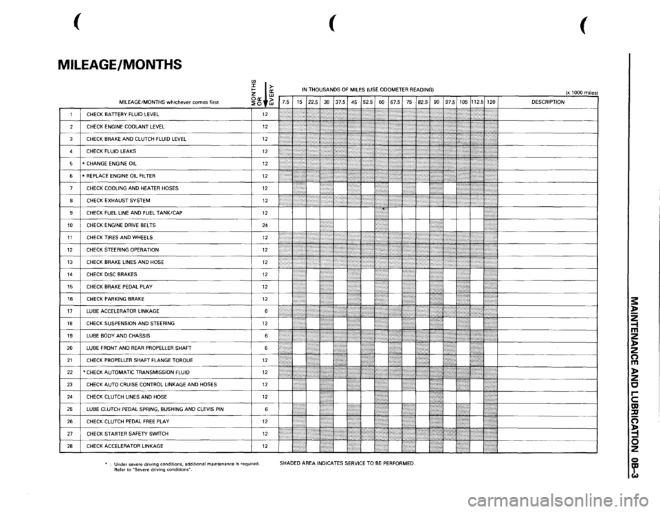
MILEAGE/MONTHS
rn
I ffi
IN THOUSANDS
OF
MILES
(USE
ODOMETER READING)
(x 1000
miles)
~ +~
7.5 15 22.5
30
37.5 45 52.5
60
67.5
75
82.5
90
97.5
105
112.5
120 DESCRIPTION
1
CHECK
BATTERY
FLUID
LEVEL
12
2'-'.:j:
:':
';;;;;
I '' ''
,,,,,,,,,:
[}
2
CHECK
ENGINE
COOLANT
LEVEL
12
':iti:·:
(''''/''?
'';?
,,,,,,,;.;.,.,....
,,,~~
3
CHECK
BRAKE
AND
CLUTCH
FLUID
LEVEL
12
:;:;:;:;:·:·:·.
\::':\' '\"':(\':'''''''''
:'·'·'·:·.,.,,,,
d~~~~~~-------------~
)''
'"''''{''''
'}';;o;o;;
l':':':·:o·.·o·····
4
CHECK
FLUID
LEAKS
12
•.•••..••• ,,......
,,,,,,,,,,,
5
* CHANGE
ENGINE
OIL
12
:.•••:•····
f ) : •
: ; ' {
1:':''''
6
*REPLACE
ENGINE
OIL
FILTER
12
{\::::::::;
[:(o:'.
7
CHECK
COOLING
AND
HEATER
HOSES
12
I : ' :
?
,,,.,,,,,.,:,
.. ;
! • !
•••••••••.
8
CHECK
EXHAUST
SYSTEM
12
I
~
J
:
: ••;·,·····,:·:';';·
•••::::::::::·:;.;
I ;J
., ..... .
9
CHECK
FUEL
LINE
AND
FUEL
TANK/CAP
12
10
CHECK
ENGINE
DRIVE
BELTS
24
. .
I
I
11
CHECKTIRESANDWHEELS
12
li
1:;:~:
}::,
..... ::::, .. ,::,:,:,:,·····
j
12
CHECK
STEERING
OPERATION
12
1
r ., .. ,,.,,.
·
I
13
CHECK
BRAKE
LINES
AND
HOSE
12
~
~
<
.,>
/ ':'??i'
}
J
t
''}{
14
CHECK
DISC
BRAKES
12
10
}}
UL
'I I
•....
15
CHECK
BRAKE
PEDAL
PLAY
12
I"
.. )t
16
CHECK
PARKING
BRAKE
12
li
I
17
LUBE
ACCELERATOR
LINKAGE
6
,,.:
....
I
18
CHECK
SUSPENSION
AND
STEERING
12
••·•••·•··•
19
LUBE
BODY
AND
CHASSIS
6
1''''':'''''''''''
20
LUBE
FRONT
AND
REAR
PROPELLER
SHAFT 6
{:
!: • :•••••l
21
CHECK
PROPELLER
SHAFT FLANGE
TORQUE
12
•
22
*CHECK AUTOMATIC TRANSMISSION
FLUID
12
... ,, ,....
@{I{
,,,,,,,,
ttJ
·~+---------------!
23
CHECK
AUTO
CRUISE
CONTROL
LINKAGE
AND
HOSES
12
~ .
:l
!•••:
24
CHECK
CLUTCH
LINES
AND
HOSE
12
25
LUBE
CLUTCH
PEDAL
SPRING,
BUSHING
AND
CLEVIS
PIN
6
l':":"·:"ii
26
CHECK
CLUTCH
PEDAL
FREE
PLAY
12
1/JJ(
21
cHEcK sTARTER SAFETY swiTCH 12
1/,,,,.,,,,,,,,,
,,,,,,,,,
-~~~--~~~~~~-~~~~~[============J
28
CHECK
ACCELERATOR
LINKAGE
12
m ::::::::]
!•'····
'.!
Under
severe driving conditions,
additional
maintenance
is required.
Refer to
"Severe
driving
conditions".
SHADED AREA
INDICATES
SERVICE
TO
BE PERFORMED.
s: ~ 2 -1 m 2 )> 2 n m )> 2 c rc m ::u n ~ 0 2 Q ~
Page 22 of 1928
OB-6 MAINTENANCE AND LUBRICATION
BRAKE SYSTEMS OPERATION
Watch for the "BRAKE" light coming on. Other
signs of possible brake trouble are such things as
repeated pulling to one side when braking, unusual
sounds
when braking or between brake
applications,
or increased brake pedal travel. If you
note one of these conditions, repair the system at
once.
For convenience, the
following should be done
when wheels are removed for rotation: Inspect lines
and hoses
for proper hookup, bindings, leaks, crack,
chafing etc.
Inspect disc brake pads for wear and
rotors
for surface condition.
Inspect other brake parts, including parking brake
drums, linings etc., at the same time. Check parking
brake adjustment.
Inspect brakes more often if habit or
conditions
result in frequent braking.
PARKING BRAKE AND TRANSMISSION
PARK MECHANISM OPERATION
Park on a fairly steep hill and hold the vehicle with
the parking brake only. This checks holding ability.
On
automatic transmission vehicles, shifting from
"P" position to the other positions cannot be made
unless
the brake pedal is depressed when the key
switch is in
"ON" position or the engine running.
WARNING
•
Before checking starter safety switch
operation below,
be sure to have enough
room around the
vehicle. Then firmly apply
both the parking brake and the regular brake.
Do not
use the accelerator pedal. If the engine
starts, be ready
to turn off the key promptly.
Take these precautions because the vehicle
could move
without warning and possibly
cause personal injury
or property damage.
STARTER SAFETY SWITCH OPERATION
(AUTOMATIC TRANSMISSION)
Check by trying to start the engine in each gear
while setting the parking brake and the foot brake.
The starter
should crank only in "P" (Park) or "N"
(Neutral).
STARTER SAFETY SWITCH OPERATION
(MANUAL TRANSMISSION)
To check, place the shift lever in "Neutral", push
the clutch pedal halfway and try to start. The starter
should not crank. The starter should crank only
when the clutch pedal is fully depressed.
ACCELERATOR LINKAGE LUBRICATION
Lubricate the accelerator pedal fulcrum pin with
chassis grease.
STEERING AND SUSPENSION
INSPECTION
Inspect front and rear suspension and steering
system
for damaged, loose or missing parts or signs
of wear. Inspect power steering lines and hoses for
proper hookup, binding, leaks, cracks, chafing, etc.
BODY AND CHASSIS LUBRICATION
Lubricate the key lock cylinders, the hood latch, the
hood and door hinges, the door check link, the
parking cable guides,
the underbody contact points,
and the linkage.
PROPELLER SHAFT INSPECTION AND
LUBRICATION
Lubricate sliding yoke and universal joints with
grease containing MOS2 (disulfide molybdenum
type grease) at the interval shown in the
Maintenance Schedule. Check for play in normal
direction of rotation of sliding yoke and universal
joints. Also check
propeller shaft flange-to-pinion
bolts for proper torque of 63 N·m (46 lb·ft) for front
and rear propeller shaft.
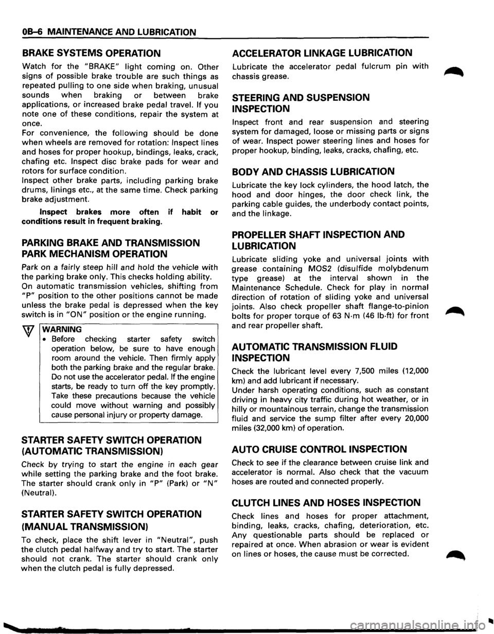
AUTOMATIC TRANSMISSION FLUID
INSPECTION
Check the lubricant level every 7,500 miles (12,000
km) and add lubricant
if necessary.
Under harsh operating conditions, such as constant
driving in heavy city traffic during
hot weather, or in
hilly or mountainous terrain, change the transmission
fluid and service the
sump filter after every 20,000
miles (32,000 km) of operation.
AUTO CRUISE CONTROL INSPECTION
Check to see if the clearance between cruise link and
accelerator is normal. Also check that the vacuum
hoses are routed and connected properly.
CLUTCH LINES AND HOSES INSPECTION
Check lines and hoses for proper attachment,
binding, leaks, cracks, chafing, deterioration, etc.
Any questionable parts should be replaced or
repaired at once. When abrasion or wear is evident
on lines or hoses, the cause must be corrected.
..
Page 24 of 1928
OB-8 MAINTENANCE AND LUBRICATION
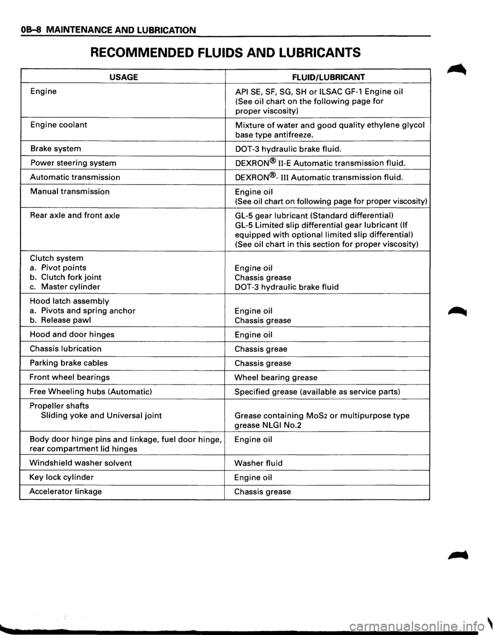
RECOMMENDED FLUIDS AND LUBRICANTS
USAGE FLUID/LUBRICANT
Engine API SE, SF, SG, SH or ILSAC GF-1 Engine oil
(See oil
chart on the following page for
proper viscosity)
Engine
coolant Mixture of water and good quality ethylene glycol
base type antifreeze.
Brake system
DOT-3 hydraulic brake fluid.
Power steering system
DEXRON® 11-E Automatic transmission fluid.
Automatic transmission DEXRON®-III Automatic transmission fluid.
Manual transmission
Engine oil
(See oil
chart on following page for proper viscosity)
Rear
axle and front axle GL-5 gear lubricant (Standard differential)
GL-5 Limited slip differential gear lubricant (If
equipped with optional limited slip differential)
(See oil
chart in this section for proper viscosity)
Clutch system
a. Pivot points Engine oil
b. Clutch fork joint Chassis grease
c. Master cylinder DOT-3 hydraulic brake fluid
Hood latch assembly
a. Pivots and spring anchor
Engine oil
b. Release pawl Chassis grease
Hood and
door hinges
Engine oil
Chassis lubrication Chassis greae
Parking brake
cables Chassis grease
Front wheel bearings Wheel bearing grease
Free
Wheeling hubs (Automatic) Specified grease (available as service parts)
Propeller shafts
Sliding yoke and Universal joint Grease containing MoS2 or multipurpose type
grease NLGI No.2
Body
door hinge pins and linkage, fuel door hinge,
Engine oil
rear compartment lid hinges
Windshield washer solvent Washer fluid
Key lock cylinder Engine oil
Accelerator linkage
Chassis grease
Page 630 of 1928
68 - 2 ENGINE COOLING
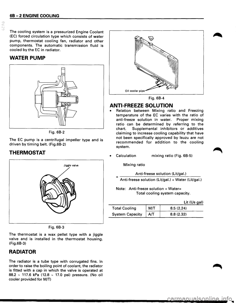
The cooling system is a pressurized Engine Coolant
(EC) forced circulation type which consists of water
pump, thermostat cooling fan, radiator and other
components. The automatic transmission fluid is
cooled by the EC in radiator.
WATER PUMP
Fig. 68-2
The
EC pump is a centrifugal impeller type and is
driven by timing belt. (Fig.68-2)
THERMOSTAT
Jiggle valve
Fig. 68-3
The
thermostat is a wax pellet type with a jiggle
valve and is installed in the thermostat housing.
(Fig.68-3)
RADIATOR
The radiator is a tube type with corrugated fins. In
order to raise the boiling point of coolant, the radiator
is fitted
with a cap in which the valve is operated at
88.2
-117.6 kPa (12.8 - 17.0 psi) pressure. (No oil
cooler
provided for M!f)
Fig. 68-4
ANTI-FREEZE SOLUTION
•
•
Relation between Mixing ratio and Freezing
temperature
of the EC varies with the ratio of
anti-freeze solution in water. Proper mixing
ratio can be determined by referring to the
chart. Supplemental inhibitors or additives
claiming to increase cooling capability that have
not been specifically approved by lsuzu are not
recommended for addition to the cooling
system.
Calculation mixing ratio (Fig. 68-5)
Mixing ratio
Anti-freese
solution (Lit/gal.) =-----------------Anti-freese solution (Lit/gal.) +Water (Lit/gal.)
Note: Anti-freeze solution +Water=
Total cooling system capacity.
Lit (Us
gal)
Total Cooling
M!f 8.5 (2.24) ~-~~--------System Capacity AfT 8.8 (2.32)
Page 632 of 1928
68 - 4 ENGINE COOLING
ON-VEHICLE SERVICE
DRAINING AND REFILLING COOLING
SYSTEM
Before draining the cooling system, inspect the sys
tem and perform any necessary service to ensure that
it is clean, does not leak and is in proper working
order. The Engine Coolant (EC) level should be be
tween the "MIN" and "MAX" lines of reserve tank
when the engine is cold. If low, check for leakage and
add
EC up to the "MAX" line. There should not be any
excessive deposit of rust or scales around the radiator
cap
or radiator filler hole, and the EC should also be
free
from oil. Replace the EC if excessively dirty.
1. Completely drain the cooling system by opening
the drain petcock at the bottom of the radiator.
2. Remove the radiator cap.
W WARNING
To avoid the danger of being burned, do not
remove the cap while the engine and radiator
are still hot. Scalding fluid and steam can be
blown out under pressure.
3. Disconnect all hoses from the EC reserve tank.
Scrub and clean the inside of the reserve tank with
soap and water. Flush it well with clean water,
then drain it. Install the reserve tank and hoses.
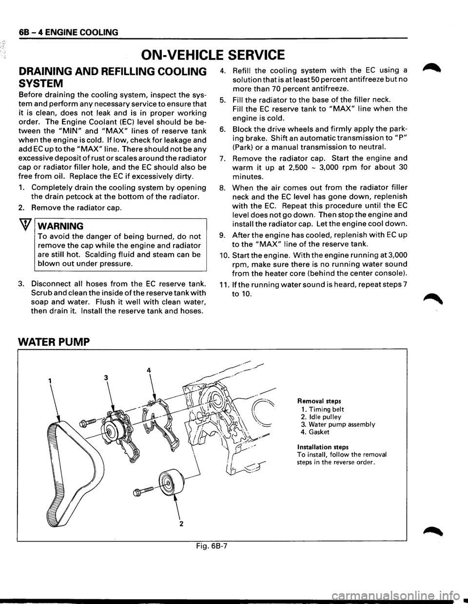
WATER PUMP
3
j
2
4. Refill the cooling system with the EC using a
solution that is at least 50 percent antifreeze but no
more than 70 percent antifreeze.
5. Fill the radiator to the base of the filler neck.
Fill the EC reserve tank to "MAX" line when the
engine is cold.
6. Block the drive wheels and firmly apply the park
ing brake.
Shift an automatic transmission to "P"
(Park) or a manual transmission to neutral.
7. Remove the radiator cap. Start the engine and
warm it up at 2,500 -3,000 rpm for about 30
minutes.
8. When the air comes out from the radiator filler
neck and the EC level has gone down, replenish
with the EC. Repeat this procedure until the EC
level does not go down. Then stop the engine and
install the radiator cap. Let the engine cool down.
9. After the engine has cooled, replenish with EC up
to the "MAX" line of the reserve tank.
10. Start the engine. With the engine running at 3,000
rpm, make sure there is no running water sound
from the heater core (behind the center console).
11. If the running water sound is heard, repeat steps 7
to 10.
Removal steps
1. Timing
belt 2. Idle pulley 3. Water pump assembly
4. Gasket
Installation steps To install, follow the removal steps in the reverse order.
Fig. 6B-7
•
Page 657 of 1928
ENGINE ELECTRICAL 601-3
ON-VEHICLE SERVICE
BATTERY CHARGING
Observe the following safety precautions when
charging the battery:
1. Never attempt to charge the battery when the
fluid level is below the lower level line on the
side
of the battery. In this case, the battery
must be replaced.
2. Pay close attention to the battery during the
charging procedure.
Battery charging
should be discontinued or the
rate
of charge reduced if the battery feels hot
to the touch.
Battery charging
should be discontinued or the
rate
of charge reduced if the battery begins to
gas or spew electrolyte from the vent holes.
3. In order to more easily view the hydrometer
blue dot or ring, it may be necessary to jiggle
or tilt the battery.
4. Battery temperature can have a great effect on
battery charging capacity.
5. The sealed battery used on this vehicle may be
either quick-charged or slow-charged in the
same manner
as other batteries.
Whichever method you decide
to use, be sure
that you
completely charge the battery. Never
partially charge the battery.
JUMP STARTING
JUMP STARTING WITH AN AUXILIARY
(BOOSTER)
BATTERY
W CAUTION:
Never push or tow the vehicle in an attempt to
start it.
Serious damage to the emission sys
tem as
well as other vehicle parts will result.
Treat both the discharged battery and the
booster battery
with great care when using
jumper cables. Carefully follow the jump start
ing procedure, being
careful at all times to
avoid sparking.
wwARNING:
Failure to carefully follow the jump starting
procedure
could result in the following:
1. Serious personal injury, particulaly to your
eyes.
2. Property damage from a battery explo
sion, battery acid, or an electrical fire.
3. Damage to the electronic components of
one or both vehicles particularly.
Never expose the battery to an open flame or elec
trical
spark. Gas generated by the battery may catch
fire
or explode.
Remove any rings, watches, or other jewelry before
working around the battery. Protect
your eyes by
wearing
an approved set of goggles.
Never allow battery fluid to come in contact with
your eyes or skin.
Never
allow battery fluid to come in contact with
fabrics or painted surfaces.
Battery
fluid is a highly corrosive acid.
Should battery fluid come in contact with your eyes,
skin, fabric, or a painted surface,
immediately and
thoroughly rinse the affected area with clean tap
water. Never
allow metal tools or jumper cables to come
in contact with the positive battery
terminal, or any
other
metal surface of the vehicle. This will protect
against a short circuit.
Always keep batteries out of the reach of young
children.
JUMP STARTING PROCEDURE
1. Set the vehicle parking brake.
If the vehicle is equipped with an automatic
transmission,
place the selector lever in the
"PARK" position.
If the vehicle is equipped with a manual trans
mission
place the shift lever in the "NEUTRAL"
position.
Turn
"OFF" the ignition.
Turn
"OFF" all lights and any other accessory
requiring
electrical power.
2. Look at the built-in hydrometer.
If the indication area of the built-in hydrometer
is
completely clear, do not try to jump start.
3. Attach the end of one jumper cable to the posi
tive
terminal of the booster battery.
Attach the other end
of the same cable to the
positive
terminal of the discharged battery.
Do not allow the vehicles to touch each other.
This
will cause a ground connection, effectively
neutralizing
the charging procedure.
Be sure that the booster battery has a 12 volt
rating.
4. Attach one end of the remaining cable to the
negative
terminal of the booster battery.
Attach the other end
of the same cable to a
solid engine ground (such as the air condition
ing compressor bracket or the generator
mounting bracket)
of the vehicle with the dis
charged battery.
This ground connection must be at
least 450
mm (18 in) from the battery of the vehicle
whose battery is being charged.
Page 873 of 1928
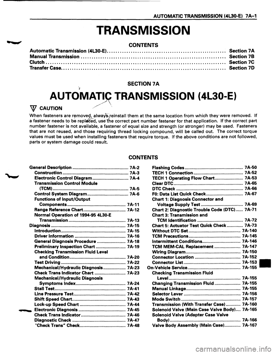
AUTOMATIC TRANSMISSION (4l30-E) 7 A-1
TRANSMISSION
CONTENTS
Automatic Transmission (4L30-E). . . . . . . . . . . . . . . . . . . . . . . . . . . . . . . . . . . . . . . . . . . . . . . . . . . . . . . Section 7 A
Manual Transmission . .
. . . . . . . . . . . . . . . . . . . . . . . . . . . . . . . . . . . . . . . . . . . . . . . . . . . . . . . . . . . . . . . . . Section
78
Clutch . . . . . . . . . . . . . . . . . . . . . . . . . . . . . . . . . . . . . . . . . . . . . . . . . . . . . . . . . . . . . . . . . . . . . . . . . . . . . . . . . . . Section 7C
Transfer Case. . . . . . . . . . . . . . . . . . . . . . . . . . . . . . . . . . . . . . . . . . . . . . . . . . . . . . . . . . . . . . . . . . . . . . . . . . . . Section 70
SECTION 7A
AUTOMAT~ TRANSMISSION (4L30-E)
/' W CAUTION ./
When fasteners are r~movec;l, alway~reinstall them at the same location from which they were removed. If
a fastener needs to be repl£ed, use1'he correct part number fastener for that application. If the correct part
number fastener is not available, a fastener of equal size and strength (or stronger) may be used. Fasteners
that are not reused, and those requiring thread locking compound, will be called out. The correct torque
values must be used when installing fasteners that require torque. If the above conditions are not followed,
parts or system damage could result.
CONTENTS
General Description ............................................. 7 A-2 Flashing Codes ............................................... 7 A-50
Construction ..................................................... 7 A-3 TECH 1 Connection ........................................ 7 A-52
Electronic Control Diagram ............................. 7A-4 TECH 1 Operating Flow Chart ....................... 7 A-53
Transmission
Control Module Clear DTC ........................................................ 7 A-65
(TCM) ............................................................. 7A-5 DTC Check ...................................................... 7 A-66
Control System Diagram ................................. 7 A-6 FO: Data List Quick Check .............................. 7A-67
Functions
of Input/Output Chart 1: Diagnosis Connector and
Components ............................................... 7A-11 Voltage Supply Test .................................. 7A-69
Range Reference
Chart .................................. 7A-12 Chart 2: Diagnostic Trouble Code (DTC) ...... 7A-71
Normal Operation of 1994-95 4L30-E Chart 3: Transmission and
Transmission .............................................. 7 A-13
TCM Identification ..................................... 7 A-72
Diagnosis ............................................................ 7A-15
Chart 5: Actuator Test Quick Check ............. 7A-73
Introduction .................................................... 7A-15 Without DTC Set .......................................... 7 A-140
Driver Information ......................................... 7 A-16 TCM Precautions .......................................... 7A-145
General Diagnosis Procedure ....................... 7A-18 Intermittent Conditions ............................... 7A-146
Preliminary Inspection Chart ........................ 7 A-19 TCM MEM-CAL Replacement ..................... 7A-147
Checking Transmission Fluid Level Wiring Diagram ............................................ 7A-150
and
Condition ............................................. 7 A-20 Connector Location
..................................... 7A-152
Test Driving .................................................... 7 A-22
Mechanical/Hydraulic Diagnosis .................. 7 A-23
Connector List .............................................. 7A-153 •
On-Vehicle
Service ........................................... 7A-155
Check Trans Indicator Chart ......................... 7 A-23 Checking Transmission Fluid
Mechanical/Hydraulic
Diagnosis Level .......................................................... 7A-155
Symptoms Index ........................................ 7A-24 Changing Transmission Fluid ..................... 7A-155
Stall Test ......................................................... 7 A-41 Manual Linkage ............................................ 7A-155
Line Pressure Test .......................................... 7 A-42
Selector Lever .............................................. 7 A-156
Shift Speed Chart ........................................... 7 A-43 Mode Switch ................................................ 7A-157
Lock-up
Speed Chart ..................................... 7 A-44 Transmission
(With Transfer Case). ........... 7A-160
....._ Electronic Diagnosis ...................................... 7 A-45 Solenoid Valve (Main Case Valve Body) .... 7A-165
Check Trans Indicator .................................... 7 A-46 Solenoid Valve (Adapter Case Valve
Diagnostic Check ........................................... 7 A-47 Body)
......................................................... 7A-166
''Check Trans" Check ..................................... 7 A-48 Valve Body Assembly (Main Case) ............. 7A-167
Page 891 of 1928
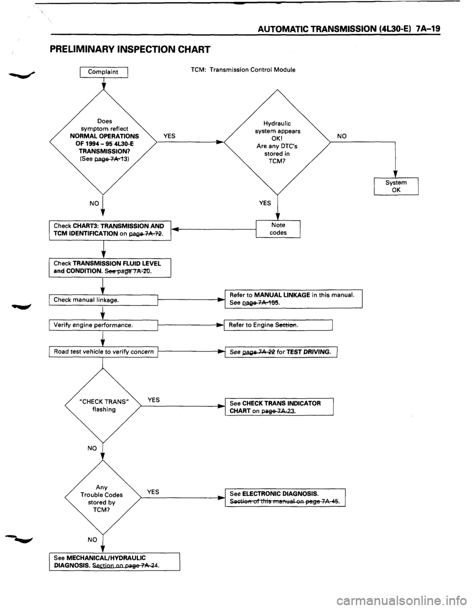
AUTOMATIC TRANSMISSION (4l30-E) 7A-19
PRELIMINARY INSPECTION CHART
Does symptom reflect
NORMAL OPERATIONS
OF 1994 -95 4L30·E
TRANSMISSION?
(See p.age-1-Ac13)
YES
Check CHART3: TRANSMISSION AND TCM IDENTIFICATION on page-~n.
Check TRANSMISSION FLUID LEVEL and CONDITION. See--page"'7A'•2'0.
Check manual linkage. TCM:
Transmission Control Module
Hydraulic system appears OK!
Are any DTC's stored in TCM?
NO
Refer to MANUAL LINKAGE in this manual.
See~.
Ll_v_e_rify_e_n_g_in_e..:.p_e~rf_or_m_a_n_c_e. ___ l--------1•~1 Refer to Engine Seeticm.
Road
test vehicle to verify concern l----------;..f~s~e;;e-;:ga;;;:;:ge~7.A:o.~2i2f;fo;;r~TiE:SsTTDD~RmlvliiNNiGG~.l
UCHECK TRANS"
flashing >--Y-ES ________ ~ See CHECK TRANS INDICATOR
CHART
on page 7A-23.
Any
Trouble Codes stored by TCM?
YES
See
MECHANICAL/HYDRAULIC DIAGNOSIS.~.
See ELECTRONIC DIAGNOSIS. ~r tliis nusnllal on-JH!ge 7A 45.