automatic transmission fluid ISUZU TROOPER 1995 User Guide
[x] Cancel search | Manufacturer: ISUZU, Model Year: 1995, Model line: TROOPER, Model: ISUZU TROOPER 1995Pages: 1928
Page 892 of 1928
7 A-20 AUTOMATIC TRANSMISSION (4L30-E)
CHECKING TRANSMISSION FLUID
LEVEL AND CONDITION
Checking fluid level and condition (color and odor)
at
regular intervals will provide early diagnosis
information about the transmission. This inform
ation may be used to correct a condition that, if not
detected early, could result in major transmission
repairs.
IMPORTANT: When new, automatic transmission
fluid is red in color. As the vehicle is driven, the
transmission
fluid will begin to look darker in color.
The
color may eventually appear light brown.
A DARK
brown color with burnt odor may indicate
excessive
fluid deterioration and signal a need for
fluid change.
FLUID LEVEL
When adding
or changing fluid, use only DEXRON
®-Ill.
Refer to the Maintenance and Lubrication (Section 0
of this manual) for maintenance information and
servicing
interval.
\f CAUTION: DO NOT OVERFILL
Overfilling will cause foaming, loss ~f fluid,
abnormal shifting and possible damage to
the transmission.
1. Start engine and drive vehicle until normal AfT
oil operating temperature is reached:
NOTE: The automatic transmission fluid level
must be checked with the vehicle at normal
A/T oil operating temperature: 75 TO 85°C
(167 TO 185°F) MEASURED WITH TECH1 SCAN
TOOL.
Temperature will greatly affect transmission
fluid level.
If the vehicle is not at normal AfT oil operating
temperature and the proper checking
procedures are
not followed, the result could
be a false reading of the fluid level indicator
and
an incorrect adjustment of the fluid level.
2. Park vehicle on level ground.
3. Move gear selector to "Park".
4. Apply parking brake and block wheels.
5. Allow vehicle to idle for 3 minutes with all
accessories turned off.
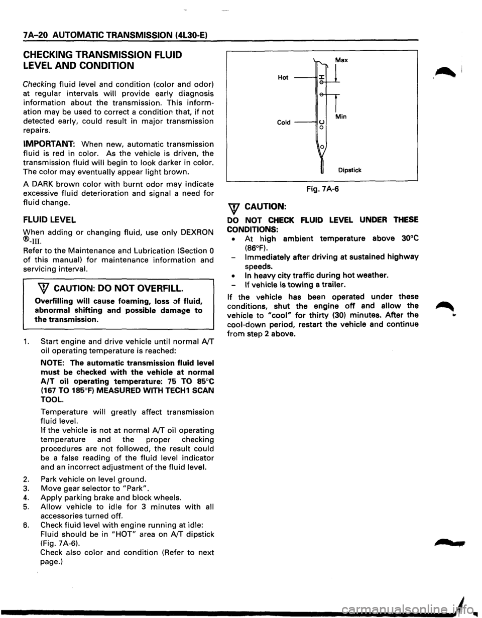
6. Check fluid level with engine running at idle:
Fluid should
be in "HOT" area on AfT dipstick
(Fig. 7A-6).
Check also color and condition (Refer to next
page.)
Hot
Cold ---IIU 0
0
Min
Dipstick
Fig. 7A-6
\f CAUTION:
DO NOT CHECK FLUID LEVEL UNDER THESE
CONDITIONS: •
At high ambient temperature above 30°C
(86°F).
Immediately after driving at sustained highway
speeds.
• In heavy city traffic during hot weather.
If vehicle is towing a trailer.
If the vehicle has been operated under these
conditions,
shut the engine off and allow the
vehicle to "cool" for thirty (30) minutes. After the
cool-down period, restart the vehicle and continue
from step 2 above.
'~I
......
Page 893 of 1928
AUTOMATIC TRANSMISSION (4L30-E) 7A-21
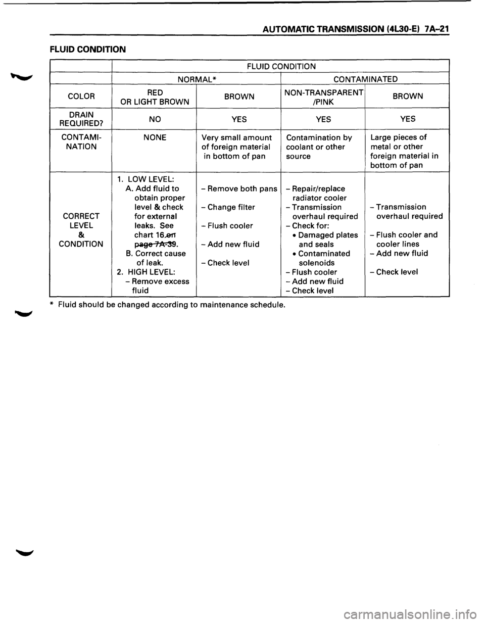
FLUID CONDITION
FLUID CONDITION
NORMAL* CONTAMINATED
COLOR
RED BROWN NON-TRANSPARENT BROWN OR LIGHT BROWN
/PINK
DRAIN NO
YES YES YES
REQUIRED?
CO NT AMI- NONE Very small amount Contamination by Large pieces of
NATION of foreign material coolant or other metal or other
in bottom of pan
source foreign material in
bottom of pan
1. LOW LEVEL:
A. Add fluid to -
Remove both pans -Repair/replace
obtain
proper radiator cooler
level
& check -Change filter -Transmission -Transmission
CORRECT for external overhaul required overhaul required
LEVEL leaks. See -Flush cooler -Check for:
& chart 16..811 • Damaged plates -Flush cooler and
CONDITION ~· -Add new fluid and seals cooler
lines
B. Correct cause • Contaminated -Add new fluid
of leak. -Check level solenoids
2. HIGH LEVEL: -Flush cooler -Check level
-Remove excess -Add new fluid
fluid -Check level
* Fluid should be changed according to maintenance schedule.
Page 896 of 1928
7 A-24 AUTOMATIC TRANSMISSION (4l30-E)
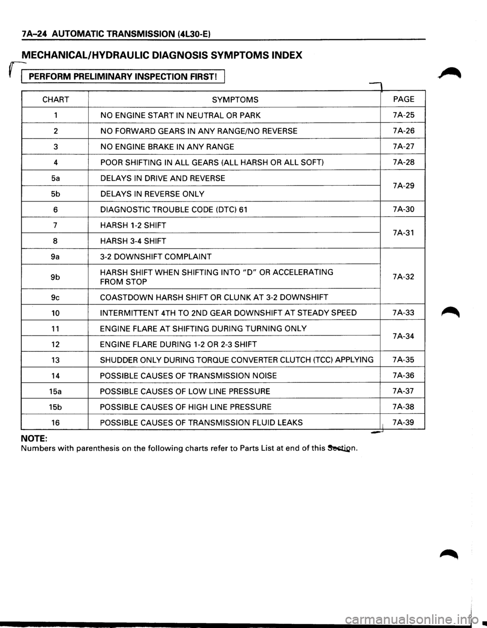
MECHANICAL/HYDRAULIC DIAGNOSIS SYMPTOMS INDEX
rr PERFORM PRELIMINARY INSPECTION FIRST! , -
CHART SYMPTOMS PAGE
1
NO ENGINE START IN NEUTRAL OR PARK 7A-25
2
NO FORWARD GEARS IN ANY RANGE/NO REVERSE 7A-26
3
NO ENGINE BRAKE IN ANY RANGE 7A-27
4
POOR SHIFTING IN ALL GEARS (ALL HARSH OR ALL SOFT) 7A-28
Sa DELAYS IN DRIVE AND REVERSE 7A-29
5b DELAYS
IN REVERSE ONLY
6 DIAGNOSTIC TROUBLE CODE (DTC) 61 7A-30
7 HARSH 1-2
SHIFT 7A-31
8 HARSH 3-4
SHIFT
9a 3-2 DOWNSHIFT
COMPLAINT
9b HARSH SHIFT WHEN SHIFTING INTO "D" OR ACCELERATING 7A-32 FROM STOP
9c COASTDOWN HARSH SHIFT OR CLUNK AT 3-2 DOWNSHIFT
10 INTERMITTENT 4TH TO 2ND GEAR DOWNSHIFT AT STEADY SPEED 7A-33
11 ENGINE FLARE AT SHIFTING
DURING TURNING ONLY 7A-34
12 ENGINE FLARE DURING 1-2 OR 2-3 SHIFT
13 SHUDDER ONLY DURING TORQUE CONVERTER CLUTCH (TCC) APPLYING 7A-35
14
POSSIBLE CAUSES OF TRANSMISSION NOISE 7A-36
15a
POSSIBLE CAUSES OF LOW LINE PRESSURE 7A-37
15b
POSSIBLE CAUSES OF HIGH LINE PRESSURE 7A-38
16
POSSIBLE CAUSES OF TRANSMISSION FLUID LEAKS It 7A-39
= -NOTE:
Numbers with parenthesis on the following charts refer to Parts List at end of this ~n.
•
Page 907 of 1928
AUTOMATIC TRANSMISSION (4L30-E) 7 A-35
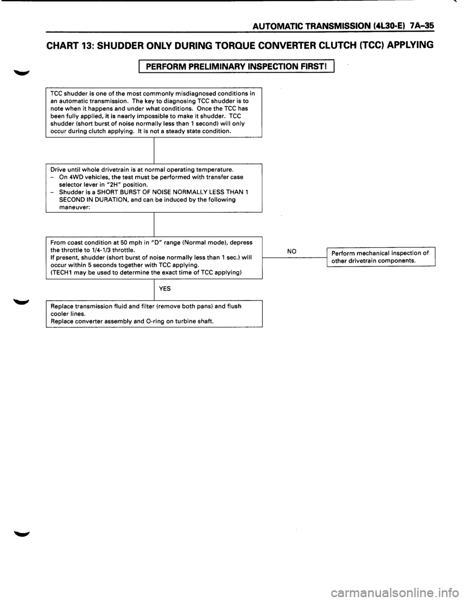
CHART 13: SHUDDER ONLY DURING TORQUE CONVERTER CLUTCH (TCC) APPLYING
PERFORM PRELIMINARY INSPECTION FIRST!
TCC shudder is one of the most commonly misdiagnosed conditions in
an automatic transmission. The key to diagnosing TCC shudder is to note when it happens and under what conditions. Once the TCC has
been fully applied, it is nearly impossible to make it shudder. TCC shudder {short burst of noise normally less than 1 second) will only
occur during clutch applying. It is not a steady state condition.
Drive
until whole drivetrain is at normal operating temperature.
-On 4WD vehicles, the test must be performed with transfer case selector lever in "2H" position.
- Shudder is a SHORT BURST OF NOISE NORMALLY LESS THAN 1
SECOND IN DURATION, and can be induced by the following maneuver:
From coast condition at
50 mph in "D" range {Normal mode), depress
the throttle to 1/4-1/3 throttle. If present, shudder {short burst of noise normally less than 1 sec.) will occur within 5 seconds together with TCC applying. {TECH1 may be used to determine the exact time of TCC applying)
YES
Replace transmission fluid and filter {remove both pans) and flush
cooler lines.
Replace
converter assembly and 0-ring on turbine shaft.
,__ __ N_o ___ ---<1 Perform mechanical inspection of I j other drivetrain components.
Page 911 of 1928
AUTOMATIC TRANSMISSION (4L30-E) 7 A-39
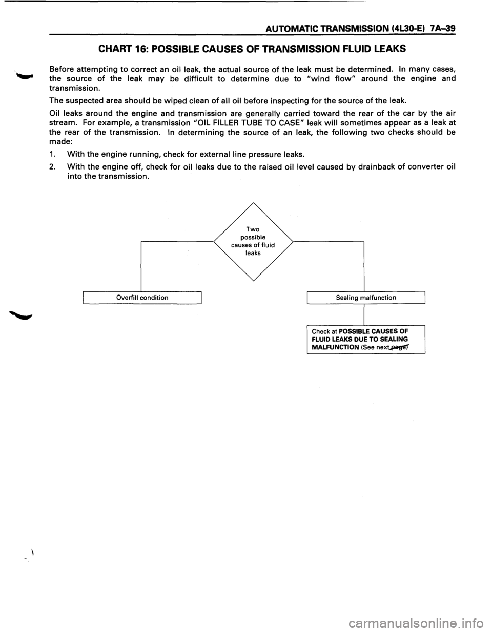
CHART 16: POSSIBLE CAUSES OF TRANSMISSION FLUID LEAKS
Before attempting to correct an oil leak, the actual source of the leak must be determined. In many cases,
the source
of the leak may be difficult to determine due to "wind flow" around the engine and
transmission.
The suspected area
should be wiped clean of all oil before inspecting for the source of the leak.
Oil leaks
around the engine and transmission are generally carried toward the rear of the car by the air
stream. For example, a transmission "OIL FILLER TUBE TO CASE" leak will sometimes appear as a leak at
the rear
of the transmission. In determining the source of an leak, the following two checks should be
made:
1. With the engine running, check for external line pressure leaks.
2. With the engine off, check for oil leaks due to the raised oil level caused by drainback of converter oil
into the transmission.
Overfill condition
Two possible causes of fluid
leaks
Sealing
malfunction
Check at POSSIBLE CAUSES OF FLUID LEAKS DUE TO SEALING
MALFUNCTION (See nex~
Page 912 of 1928
7 A-40 AUTOMATIC TRANSMISSION (4L30-E)
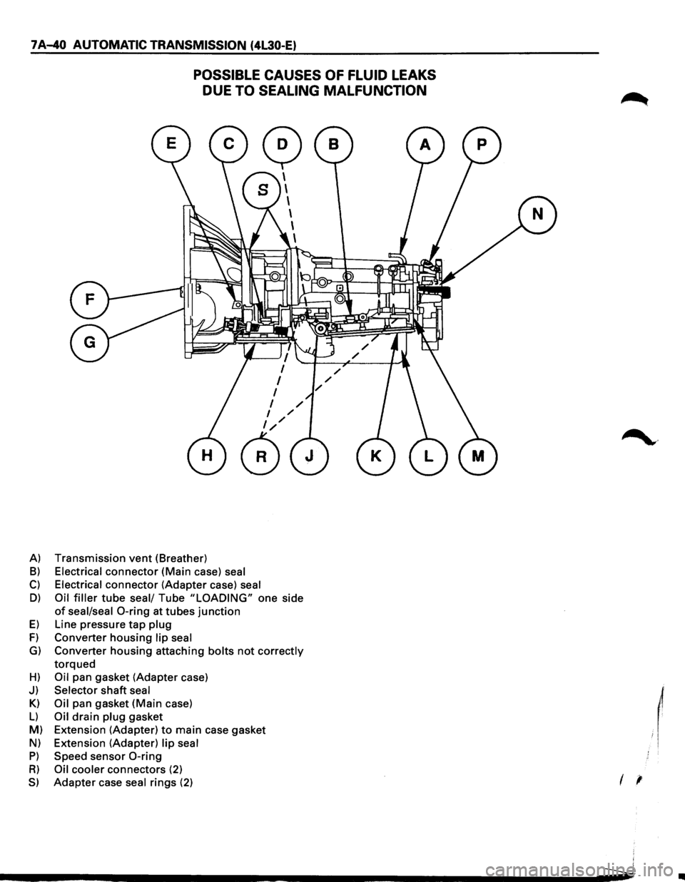
POSSIBLE CAUSES OF FLUID LEAKS
DUE
TO SEALING MALFUNCTION
A) Transmission vent (Breather)
B) Electrical connector (Main case) seal
C) Electrical connector (Adapter case) seal
D) Oil filler tube seal/ Tube "LOADING" one side
of seal/seal 0-ring at tubes junction
E) Line pressure tap plug
F) Converter housing lip seal
G) Converter housing attaching bolts not correctly
torqued
H) Oil pan gasket (Adapter case)
J) Selector shaft seal
Kl
Oil pan gasket (Main case)
L) Oil drain plug gasket
M) Extension (Adapter)
to main case gasket
Nl Extension (Adapter) lip seal
P) Speed sensor 0-ring
R) Oil cooler connectors (2)
S) Adapter case seal rings (2)
~·
I '
..
Page 913 of 1928
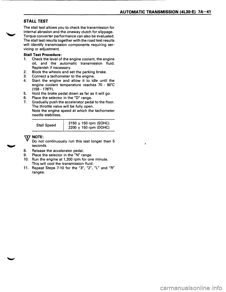
STALL TEST
The stall test allows you to check the transmission for
internal abrasion and the oneway clutch for slippage.
Torque converter performance can also be evaluated.
The
stall test results together with the road test results
will identify transmission components requiring ser
vicing or adjustment.
Stall Test Procedure:
1. Check the level of the engine coolant, the engine
oil, and the automatic transmission fluid.
Replenish
if necessary.
2. Block the wheels and set the parking brake.
3. Connect a tachometer to the engine.
4. Start the engine and allow it to idle until the
engine coolant temperature reaches
70 -8o·c
(158 -176.F).
5. Hold the brake pedal down as far as it will go.
6. Place the selector in the "D" range.
7. Gradually push the accelerator pedal to the floor.
The throttle valve
will be fully open.
Note the engine speed at which the tachometer
needle stabilizes.
Stall Speed
\fl NOTE:
2150 ± 150 rpm (SOHC)
2200 ± 150 rpm (DOHC)
VI Do not continuously run this test longer than 5
........, seconds.
8. Release the accelerator pedal.
9. Place the selector in the "N" range.
10. Run the engine at 1,200 rpm for one minute.
This
will cool the transmission fluid.
11. Repeat Steps 7-10 for the "3", "2", "L" and "R"
ranges.
AUTOMATIC TRANSMISSION (4L30-E) 7A-41
Page 914 of 1928
7 A-42 AUTOMATIC TRANSMISSION (4L30-E)
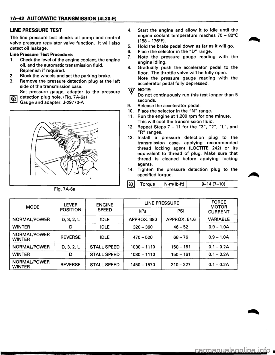
LINE PRESSURE TEST
The line pressure test checks oil pump and control
valve
pressure regulator valve function. It will also
detect oil leakage.
Line Pressure Test Procedure:
1. Check the level of the engine coolant, the engine
oil, and the automatic transmission fluid.
Replenish
if required.
2. Block the wheels and set the parking brake.
3. Remove the pressure detection plug at the left
side of the transmission case.
Set pressure gauge, adapter
to the pressure
l"iC\1 detection plug hole. (Fig. 7 A-6a)
~ Gauge and adapter: J-29770-A
Fig. 7A-6a
LEVER ENGINE
MODE
POSITION
SPEED
NORMAL/POWER D,3,2, L IDLE
WINTER D IDLE
NORMAL/POWER REVERSE IDLE WINTER
NORMAL/POWER
D,3,2,L STALL SPEED
WINTER D STALL SPEED
NORMAL/POWER REVERSE STALL SPEED WINTER
4.
5.
6.
7.
8.
9.
10.
11.
Start the engine and allow it to idle until the
engine
coolant temperature reaches 70 -80°C
(158-176°F).
Hold
the brake pedal down as far as it will go.
Place the selector in the "D" range.
Note the pressure gauge reading
with the
engine
idling.
Gradually
push the accelerator pedal to the
floor. The throttle valve will be fully open.
Note the pressure gauge reading
with the
accelerator
pedal fully depressed.
NOTE:
Do not continuously run this test longer than 5
seconds.
Release the accelerator pedal.
Place
the selector in the "N" range.
Run the engine at
1,200 rpm for one minute.
This
will cool the transmission fluid.
12. Repeat Steps 7-11 for the "3", "2", "L", and
"R" ranges.
13.
Install a pressure detection plug to the
transmission case,
applying recommended
thread
locking agent (LOCTITE 242) or its
equivalent to thread
of plug. Make sure that
thread is cleaned before applying locking
agents.
14. Tighten the pressure detection plug to the
specified torque.
~~~ Torque N·mOb·ft) / 9-14 (7-10)
LINE
PRESSURE FORCE
MOTOR kPa PSI CURRENT
APPROX. 380 APPROX. 54.6 VARIABLE
320-360 46-52 0.9 -1.0A
470-520 68-76 0.9 -1.0A
1030-1110 150-161 0.1-0.2A
1030-1110 150-161 0.1-0.2A
1450-1570 210-227 0.1-0.2A
•
Page 966 of 1928
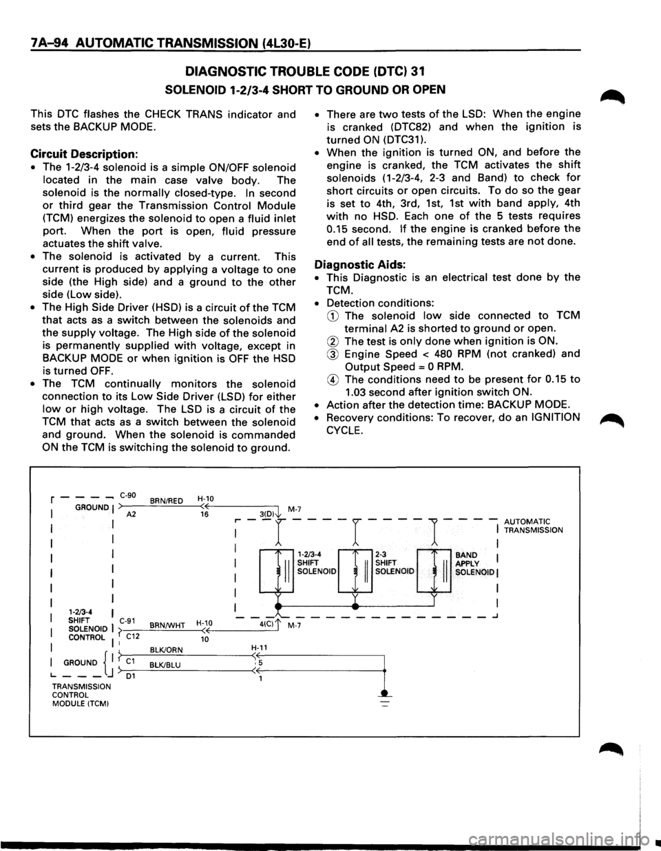
7 A-94 AUTOMATIC TRANSMISSION (4l30-E)
DIAGNOSTIC TROUBLE CODE (DTC) 31
SOLENOID 1-2/3-4 SHORT TO GROUND OR OPEN
This DTC flashes the CHECK TRANS indicator and
sets
the BACKUP MODE.
Circuit Description:
• The 1-2/3-4 solenoid is a simple ON/OFF solenoid
located
in the main case valve body. The
solenoid is the normally closed-type. In second
or third gear the Transmission Control Module
(TCM) energizes the solenoid to open a fluid inlet
port. When the port is open, fluid pressure
actuates the
shift valve.
•
The solenoid is activated by a current. This
current is produced by applying a voltage to one
side (the High side) and a
ground to the other
side (Low side).
• The High Side Driver (HSD) is a circuit of the TCM
that acts as a switch between the solenoids and
the
supply voltage. The High side of the solenoid
is permanently supplied with voltage, except in
BACKUP
MODE or when ignition is OFF the HSD
is turned OFF.
• The TCM continually monitors the solenoid
connection to its Low Side Driver (LSD) for either
low or high voltage. The LSD is a circuit of the
TCM that acts as a switch between the solenoid
and ground. When the solenoid is commanded
ON the TCM is switching the solenoid to ground.
r----C-90 BRN/RED H-10
• There are two tests of the LSD: When the engine
is cranked (DTC82) and when the ignition is
turned ON (DTC31 ).
• When the ignition is turned ON, and before the
engine is cranked, the TCM activates the shift
solenoids (1-2/3-4, 2-3 and Band) to check for
short circuits or open circuits. To do so the gear
is set
to 4th, 3rd, 1st, 1st with band apply, 4th
with no HSD. Each one of the 5 tests requires
0.15 second. If the engine is cranked before the
end of all tests, the remaining tests are not done.
Diagnostic Aids:
• This Diagnostic is an electrical test done by the
TCM.
• Detection conditions:
CD The solenoid low side connected to TCM
terminal A2 is shorted to ground or open.
® The test is only done when ignition is ON.
® Engine Speed < 480 RPM (not cranked) and
Output Speed = 0 RPM.
@ The conditions need to be present for 0.15 to
1.03 second after ignition switch ON.
•
Action after the detection time: BACKUP MODE.
•
Recovery conditions: To recover, do an IGNITION
CYCLE.
I GROUND I A2 3(D)j,. M-7 ( 16
I I
I I
I I
I
I
I
I 1·2/3·4
SHIFT C-91
I SOLENOID I j> BRN/WHT
I
CONTROL I I C12
I GROUND { I ? C1
BLK/ORN
J ) BLK/BLU
L..---D1 TRANSMISSION
CONTROL MODULE
(TCM)
H-10 ( 10
~ --r ----r ----1----~ ~~~~~~~~ION
I I
1m4 rnH SHIFT SHIFT II SOLENOID II SOLENOID
-y
-_........_ __________
--41Clf M-7
II
SAND I APPLY SOLENOID I
I
I
---.J
•
Page 968 of 1928
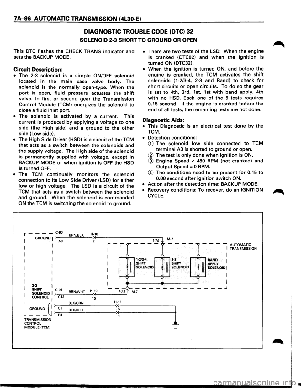
7 A-96 AUTOMATIC TRANSMISSION (4l30-E)
DIAGNOSTIC TROUBLE CODE (DTC) 32
SOLENOID 2-3 SHORT TO GROUND OR OPEN
This DTC flashes the CHECK TRANS indicator and
sets
the BACKUP MODE.
Circuit Description:
• The 2-3 solenoid is a simple ON/OFF solenoid
located in the main case valve body. The
solenoid is the normally open-type. When the
port is open, fluid pressure actuates the shift
valve. In first or second gear the Transmission
Control Module (TCM) energizes the solenoid to
close a fluid inlet port.
• The solenoid is activated by a current. This
current is produced by applying a voltage to one
side (the High side) and a ground to the other
side (Low side). .
• The High Side Driver (HSD) is a circuit of the TCM
that acts as a switch between the solenoids and
the supply voltage. The High side of the solenoid
is permanently supplied with voltage, except in
BACKUP
MODE or when ignition is OFF the HSD
is
turned OFF.
•
The TCM continually monitors the solenoid
connection to its Low Side Driver (LSD) for either
low or high voltage. The LSD is a circuit of the
TCM that acts as a switch between the solenoid
and ground. When the solenoid is commanded
ON the TCM is switching the solenoid to ground.
r---_ c-9o
BRN/BLK H-10
I GROUNDJ) (( A3 2
• There are two tests of the LSD: When the engine
is cranked (DTC82) and when the ignition is
turned ON (DTC32).
• When the ignition is turned ON, and before the
engine is cranked, the TCM activates the shift
solenoids (1-2/3-4, 2-3 and Band) to check for
short circuits or open circuits. To do so the gear
is set to 4th, 3rd, 1st, 1st with band apply, 4th
with no HSD. Each one of the 5 tests requires
0.15 second. If the engine is cranked before the
end of all tests, the remaining tests are not done.
Diagnostic Aids:
• This Diagnostic is an electrical test done by the
TCM.
• Detection conditions:
CD The solenoid low side connected to TCM
terminal A3 is shorted to ground or open.
@ The test is only done when ignition is ON.
@ Engine Speed < 480 RPM (not cranked) and
Output Speed = 0 RPM.
@ The conditions need to be present for 0.15 to
0.88 second after ignition switch ON.
•
Action after the detection time: BACKUP MODE.
•
Recovery conditions: To recover, do an IGNITION
CYCLE.
1(A) '1 M-7
,.... --r ----r ----
1 - -- -
AUTOMATIC I
I TRANSMISSION
I I
I I
I I
I BAND I APPLY I SOLENOID!
I
I
I I
I
I
I
I
I I
I I
I 2·3 I SHIFT C-91 H-10
I SOLENOID I
( BRN/WHT (
I
CONTROl I I C12 10
I GROUND { I ? C1
BLK/ORN
j) BLK/BLU L.---D1
1-2/3-4 2-3
II
SHIFT
II
SHIFT
II SOLENOID SOLENOID
-"--------------..J
TRANSMISSION
CONTROL
MODULE (TCM)
•